Bin Xie e-mail:
[email protected]
Run Hu e-mail:
[email protected]
Xiaobing Luo* e-mail:
[email protected]
State Key Laboratory of Coal Combustion and Thermal Packaging Laboratory, School of Energy and Power Engineering, Huazhong University of Science and Technology Wuhan, China
Quantum Dots-Converted LightEmitting Diodes Packaging for Lighting and Display: Status and Perspectives Recent years, semiconductor quantum dots (QDs) have attracted tremendous attentions for their unique characteristics for solid-state lighting and thin-film display applications. The pure and tunable spectra of QDs make it possible to simultaneously achieve excellent color rendering properties and high luminous efficiency when combining colloidal QDs with light emitting diodes (LEDs). Due to its solution-based synthetic route, QDs are impractical for fabrication of LED. QDs have to be incorporated into polymer matrix, and the mixture is dispensed into the LED mold or placed onto the LED to fabricate the QD-LEDs, which is known as the packaging process. In this process, the compatibility of QDs’ surface ligands with the polymer matrix should be ensured, otherwise the poor compatibility can lead to agglomeration or surface damage of QDs. Besides, combination of QDs-polymer with LED chip is a key step that converts part of blue light into other wavelengths of light, so as to generate white light in the end. Since QD-LEDs consist of three or more kinds of QDs, the spectra distribution should be optimized to achieve a high color rendering ability. This requires both theoretical spectra optimization and experimental validation. In addition, to prolong the reliability and lifetime of QD-LEDs, QDs have to be protected from oxygen and moisture penetration. And the heat generation inside of the package should be well-controlled because high temperature results in QDs thermal quenching, consequently deteriorates QD-LEDs’ performance greatly. Overall, QD-LEDs packaging and applications present the above-mentioned technical challenges. A profound and comprehensive understanding of these problems enables the advancements of QD-LEDs packaging processes and designs. In this review, we summarized the recent progress in the packaging of QD-LEDs. The wide applications of QD-LEDs in lighting and display were overviewed, followed by the challenges and the corresponding progresses for the QD-LEDs packaging. This is a domain in which significant progress has been achieved in the last decade, and reporting on these advances will facilitate state-of-the-art QD-LEDs packaging and application technologies. Key words: quantum dots, light emitting diode, packaging, color rendering index
1
Introduction
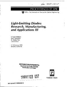
Semiconductor quantum dots (QDs), as a promising material for absorbing and converting light energy, have attracted extensive scientific and industrial interests [1-3]. Since the emission and absorption characteristics of QDs are dependent on the particles’ size, their band structures can be tuned according to the quantum confinement effect (QCE) by varying the particles’ size or compositions, as shown in Figure 1. The elements in QDs are usually in group II-VI such as CdSe [4], group III-V such as InP [5], and group I-III-VI such as CuInS2 [6]. Due to their superior optical characteristics, QDs have been proven to be extremely suitable for many applications such as optically or electrically pumped lasers, full color displays, lightemitting diodes (LEDs) and biosensors [7-10]. Among these applications, QD-converted LEDs (QD-LEDs) are the most attractive application.There are two types of QD-LEDs, the differences are that one is based on photo-excited QDs (photoluminescence QD-LEDs), and another is electro-excited QDs (electroluminescence QD-LEDs). Here we focus on the photoluminescence QD-LEDs since they are the most commonly used type.
Fig. 1. (a) Composition-dependent change of the emission color from colloidal solutions of all-inorganic perovskite cesium lead halide (CsPbX3, X=Cl, Br, I). (b) Optical
1
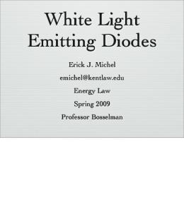
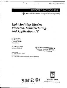
Figure 2 shows the spectra distribution and photographs of a 46’’ QD-LEDs backlight unit (BLU) developed by Samsung displays. The QD LED BLU (left of Figure 2(b)) achieved 30% more NTSC color gamut than the conventional LED BLU (right of Figure 2(b)). Furthermore, the color quality of QD-LCD is comparable to that of organic LED (OLED) displays while achieved at the cost of an LCD display. Thus, it represents an emerging technology and is expected to compete with OLED in the near future. 2) General lighting. As related to the human eyes, the correlated color temperature (CCT) and color rendering index (CRI) are two major concerns of solid-state lighting (SSL). The CCT of a white light source is defined as the temperature of a planckian black-body radiator, whose color is closest to the color of the white light source. The CRI of a light source is defined as the ability of the light source to render the true colors of any objects (Reference to Section 4.2 for details). The pc-LEDs produce ‘cold’ white light with CCT>5000K and CRI90 while maintaining an efficiency of 65 lm/W [21]. Figure 3 shows the efficiency and CRI for different lighting applications, it is seen that the first commercial QDLEDs have high CRI as well as high luminous efficiency. In their technology, QDs in a transparent matrix are dispersed onto a substrate to form a QDs film with recorded solid-state QDs photoluminescence efficiency of (95%±5). In 2008, Evident Technologies also developed their Christmas lights used blue LEDs to excite a mixture of CdSe/ZnS QDs dispersed in a polymer matrix to achieve monochromatic color emission across the visible spectrum, including colors such as purple and aqua that can typically only be achieved by color filtering of white light [22].
absorption and (c) PL spectra of colloidal CsPbX3 QDs [17]. So far, the overall efficiency of electroluminescence QDLEDs remained lower compared to that of photoluminescence QD-LEDs because of their charge injection problem. The conventional LEDs usually are phosphor-converted LEDs (pcLEDs), which combine blue LED chips with yellow phosphors, e.g. yttrium aluminum garnet doped with cerium (YAG: Ce3+) [11-13]. For pc-LEDs, the color rendering index (CRI) is quite low owing to the lack of red component in the emission spectrum [14]. Moreover, the broad full-width-at-half-maximum (FWHM) of phosphors (50 nm-100nm) [15, 16], makes it difficult to tune the spectra distribution of pc-LEDs since it has significant overlap in the blue-green and green-red regions. In contrast, QDLEDs have good CRI, wide absorption and narrow emission spectra. QD-LEDs are usually used in thin-film display and general lighting applications, which is introduced in categories as follows: 1) Backlighting for displays. Color gamut is one of the most important parameters of display devices. This industry uses chromaticity diagrams and color gamut standards to quantify the color purity. The International Commission on Illumination (CIE) has established a chromaticity diagram known as CIE 1931 color space. Color gamut represents all colors that can be created by mixing primary colors. In 2013, Sony’s commercial application of colloidal QD-based liquid crystal display (LCD) televisions use edge-mounted red and green QDs to optically down-convert part of the blue LED backlight and reemit red and green light. To achieve long-term luminescent stability, QDs were dispersed in an acrylate polymer and encapsulated in thin glass tubes to avoid oxygen and moisture exposure. The use of QDs for backlighting fulfills more than 100% of the National Television System Committee (NTSC) television color gamut standard [18].
Fig. 2. (a) Light intensity spectra (solid line) and brightness (hatched area) of the QD-LED (blue) and the phosphor-LED (gray). Inset of Fig. 2a) indicates the color triangles created by the QD-LED (white) and the phosphor converted-LED (yellow). (b) 46-inch LCD TV panel (Samsung displays) adapting QD-LEDs BLU (left) and phosphor LED BLU (right) [18].
Fig. 3. (a) Efficiency and CRI for different lighting applications. The first commercial QDs-converted SSL
2
QDs are blended with polymeric matrix which can be processed or manipulated into the solid-state material, then the mixture is stirred to obtain homogeneous QDs-polymer hybrid material. In this process, the compatibility of QDs’ surface ligands with the polymer should be ensured. Otherwise the poor compatibility can lead to agglomeration or surface damage of QDs. (b) Solidification of QDs-polymer mixture. Firstly the organic solvent in the QDs-polymer mixture is moved in the vacuum chamber, then the mixture is fabricated into solid film or stick. According to the characteristic of polymer matrix, solidification can be achieved different methods, such as by electrochemical reactions [23-25], utilization of gamma and UVirradiation [26-28], and thermal curing reactions [29-31]. (c) Combination of QDs-polymer with LED chip. The QDspolymer composite is fabricated onto LED chip with blue emission, and QDs convert part of the blue light into other expected wavelengths, resulting in white light after color mixing. The optical efficiency as well as the thermal performance of QDLEDs are dependent on the packaging structure. Besides, the color rendering quality is determined by the color mixing process. Therefore, packaging structure needs well-controlled to achieve high light output and better heat dissipation performance, and the color mixing of different QDs particle should be optimized for higher color rendering quality. (d) Encapsulation. The encapsulant is filled into the interspace between the QDs-polymer film and LED chip to protect the chip and bonding wires. The QDs are also protected by encapsulant to avoid direct contact with oxygen and moisture. The encapsulant coating can improve the long-term stability and its morphology can also influence the light output efficiency. The packaging process of the on-chip type QD-LEDs is quite similar with the remote type. Firstly the QDs are mixed with polymer matrix (a). Then the QDs-polymer mixture is coating onto the LED chip (b2). After the solidification of QDs-polymer mixture (c2), the whole QDs-polymer gel is covered by encapsulant (d2) to protect the chip and QDs.
solution developed by QD Vision and Nexxus Lighting has a high CRI while maintaining high luminous efficiency. (b) Photographs comparing the illumination of objects with an incandescent lamp, a cool white LED, and the QD-LEDs. Photographs were quoted from QD Vision, Inc. From above introductions, QD-LED are expected to create next-generation displays and high quality lighting with better color gamut, higher efficiency, and high CRI. However, to quickly penetrate the applications, many packaging issues of the QD-LEDs should be solved. QDs have to be incorporated into polymer matrix, and the resulting QDs mixture is dispensed into the LED mold or placed onto the LED in terms of QDs-polymer film, which is known as the packaging process. Packaging is an essential step, which not only can ensure better performance of LED devices by enhancing reliability and optical characteristics, but can also realize control and adjustment of the working performance. Therefore, the packaging process needs to be deeply studied to achieve high-quality QD-LEDs devices, which is the right motivation behind this review. Here, the basic knowledge of QD-LEDs in lighting and display was introduced, followed by the discussion on the challenges and the corresponding progresses for the QD-LEDs packaging.
2
Brief knowledge of QD-LEDs packaging
Figure 4 shows the packaging process of QD-LEDs. Typically there are two types of packaging structure of QD-LEDs, one is the remote type and another is the on-chip type. Taking the remote type as an example, step by step, the packaging processes are as follows.
3
Challenges in QD-LEDs packaging
From the packaging processes shown in Figure 4, there are several key problems in QD-LEDs packaging and applications. Compatibility problem of QDs and polymers. Due to the solution-based synthetic route in which QDs are suspended in some organic solvent, QDs are impractical for fabrication and integration of light-emitting devices directly. So the solidification of well-defined QDs-polymer hybrid materials is pre-requisite before applications. However, hydrophobic surface of typical QDs is generally incompatible with the conventional LED packaging process, where the QDs are physically blended with silicone or epoxy resin. The hydrophobic organic ligands on QDs’ surface damage the polymerization of resin encapsulation, namely the catalyst poisoning effect [32]. Besides, the incompatibility of QDs’ surface with polymer matrix can result in QDs agglomeration, consequently decrease the photoluminescence efficiency of QDs [33-35]. Combination of QDs with LEDs. Combination of QDspolymer with LED chip, as shown in Figure 4(c), is the key component that converts part of blue light into other wavelengths of light. QD-LEDs always consist of three or more kinds of QDs. Therefore, the spectra distribution should be optimized, through tuning the wavelengths and mixing ratio of QDs components, to achieve a high color rendering ability. This requires both theoretical spectra optimization and experimental validation. In addition, the packaging structure plays an important role in determining the final optical characteristics of QD-LEDs.
Fig. 4. Typical packaging process of QD-LEDs. (a)-(b)-(c)-(d) are the packaging steps for remote type QD-LEDs and (a)(b2)-(c2)-(d2) are the packaging steps for on-chip type QDLEDs. (a) QDs mixed with polymer matrix; (b) Solidification of QDs-polymer mixture; (c) Combination of QDs-polymer with LED chip; (d) Encapsulation. (b2) Coating of QDspolymer mixture. (c2) Solidification of QDs-polymer mixture. (d2) Encapsulation. (a) QDs mixed with polymer matrix. The solution-based
3
Improper QDs-polymer morphology and QDs particle distribution may cause low efficiency or poor color quality. The packaging structure should be well designed in this process. Reliability and lifetime of QD-LEDs. To prolong the reliability and lifetime of QD-LEDs, the QDs have to be protected from oxygen and moisture. Besides, the heat generation from QDs should be well-controlled because high temperature results in QDs’ thermal quenching, consequently deteriorates QD-LEDs’ performance greatly. In the last decade, most of the progresses in QD-LEDs packaging are aiming to solve aforementioned problems, which will be reviewed as follows.
4
Progresses in QD-LEDs packaging and applications 4.1 Compatibility of QDs and polymer matrix
Before the applications of white LED (WLED), issues about the poor compatibility of QDs with polymeric environments, should be resolved. Although techniques for incorporating QDs in thin films are well developed, stabilizing these QDs in bulk polymer matrices remains a challenge. The approaches are mainly focused on the preparation of welldispersed QDs inside polymers, so that the photoluminescence properties of QDs are not affected [36, 37]. In addition, the QDs polymer composites are required to be transparent when encapsulated into the LEDs. Therefore, it is required to establish methods to obtain QDs polymer materials with high transparency and uniformity.
Fig. 5. CdTe/polystyrene hybrid materials using a polymerizable surfactant. Aqueous CdTe QDs were preprepared, and polymerizable OVDAC was used as a surfactant to transfer negatively charged CdTe QDs to a styrene solution. After radical polymerization, a transparent CdTe-PS composite was obtained [41].
4.1.1 Modification of the QDs’ surface chemistry The main strategy to improve the compatibility and dispersibility of the QDs and polymer is to coat compatible ligands at the surface of the QDs. For example, coating CdS QDs with ligands functionalized by phenyl groups improved the dispersibility of the QDs in pyridine [38], and oleic acid ligands at the QDs surface promoted the solubility of the QDs in PMMA and PS, while an octylamine at the QDs surface results in a strong quenching of band edge emission [39]. By introducing covalent bonds, such as 4thiomethylstyrene as both a capping ligand and a co-monomer to replace the trioctylphosphane oxide (TOPO) on CdSe, QDspolystyrene composites were successfully obtained after polymerization [40]. Ligands modification can be realized by the direct modification of the periphery with surfactants, which is able to copolymerize with the growing polymer chains. Zhang et al. [41] have demonstrated a method by using octadecyl-p-vinylbenzyldimethylammonium chloride OVDAC) as a polymerizable surfactant to transfer the aqueous CdTe QDs into styrene or methyl methacrylate monomer solutions, a transparent CdTe-PS composite was obtained. Figure 5 shows these CdTe/polystyrene hybrid materials.
4.1.2 Incorporation of QDs into polymer materials. The QDs can be encapsulated by an optically transparent barrier material to minimize the incompatibility problem. For instance, QDs-silica composite including silica shell overcoating individual QDs [42-44], multiple QDs-embedding silica matrix [45, 46], and QDs-silica monolith [47, 48] were obtained in terms of powder-typed QDs-silica composites by the microemulsion method. Since the surface of QDs is coated with silica layer, catalyst poisoning does not occur during the curing process of the silicone [45]. Compared to the QDs-WLED with bare QDs, the silica-embedded CIS/ZnS QDs showed a longer operational times (1~3 h), but a lower blue-to-yellow conversion efficiency due to the PL reduction concomitant to silica embedding procedure [49]. Instead of the modification of surface ligands of nanocrystals, electrostatic interaction between negatively charged QDs and a positively charged building block can be the main driving force to achieve the desired hybrid QDs-polymer material [50-52]. The QDs act as physical cross-linking centers, and the resulting complexes are easily shaped into various fluorescent structures and materials, the stability of the photoluminescence properties was improved as well. Tetsuka et al. [53] demonstrated a method of incorporating the hydrophilic CdSe/ZnS QDs into a transparent and flexible clay host, which was realized through electrostatic interaction between QDs surface and clay platelets. Similarly, Qi et al. [54] proposed a method combining the electrostatic modification of CdTe QDs and the titania sol-gel process to fabricate stable QDs/TiO2 hybrid film. The CdTe QDs were wrapped in a cationic surfactant
4
and a surfactant-encapsulated QDs hybrid particle with hydroxyl active sites on its periphery was formed. Due to this structure which QDs’ surface were better passivated by the polymer, the original luminescent property of QDs and the flexible of titania sol-gel materials were retained in the resulting hybrid films.
spectrum distribution of QD-LEDs. Before covering the researches of spectra optimization, we first introduce several concepts of color science. 1) Color matching functions and chromaticity diagram. Since light causes different levels of excitation of red, green and blue cones, the sensation of color and luminous flux of a particular color varies slightly among different individuals. Furthermore, the sensation of color is a subjective quality that cannot be measured objectively. Therefore, the CIE has standardized the measurement of color using color matching functions and the chromaticity diagram. Figure 7 shows the CIE color matching functions. The three color matching functions x(λ), y(λ), and z(λ) approximately correspond to the eye sensitivity curves of the red, green, and blue cones, respectively.
4.1.3 Embedding QDs into polymer microspheres. Another effective way to improve the dispersibility and stability of QDs inside the polymers is to embed QDs into a microspheres. Swelling is the simplest method for preparing QDs polymer microspheres. The swelling polymers traps the QDs inside the particle, and the subsequent washing of the residue causes the polymer to shrink, thus trapping the QDs inside the microspheres [55]. Chen et al. [56] obtained luminescent microbeans (LMBs) by a swelling method which combines mesoporous silica particles with the CuInS2 (CIS) QDs. Figure 6(a) shows the schematic diagram of this swelling and solventevaporation method, Figure 6(b)-(d) show the images of the asprepared LMBs. The mesoporous structures work as the lattice to avoid aggregation of the QDs.
Fig. 7. CIE (1931) color matching functions. The y(λ) color matching function is identical to the eye sensitivity function V(λ). The perception of colored light can be analyzed in terms of the degree to which the light stimulates the three types of cones. The degree of stimulation of the three types of cones is given by
Fig. 6 (a) Schematic of incorporation of QDs into a silica bean by the swelling and solvent-evaporation method. The silica microbeans solution were pre-heated at 60°C, whereby the pores in the silica increase in size allowing the QDs with their outer organic ligands to enter into the mesoporous structure. The final LMBs powders were obtained after drying process. (b) TEM image of QDs in LMBs. (c) SEM image of LMBs. (d) Photograph of as-prepared LMBs under daylight. (e) Photograph of LMBs under UV light (365 nm) [56].
X x ( ) P( )d
(1)
Y y ( ) P( )d
(2)
Z z ( ) P( )d
(3)
The swelling method results in as many as 103-105 nanoparticles embedded into polymer microspheres, while there is no Förster energy transfer between the QDs, which indicates that the embedded QDs are well dispersed without aggregation [55, 57]. Furthermore, due to the restrict of the mesoporous, only QDs within a certain size range can be incorporated, thus narrowing the QDs size distribution, and consequently narrowing the emission spectra of the hybrid microspheres. The main concern of this method is that the QDs’ penetration is highly dependent on the swelling conditions and the degree of crosslinking. The QDs only penetrated into the edge of the microspheres in the condition of low degrees of swelling or high cross-linking densities, as revealed by Bradley et al [58].
Where P(λ) is the spectral power distribution, X, Y, and Z are the tristimulus values that indicate the relative stimulation of each of the three cones. The chromaticity coordinates x and y are calculated from the tristimulus values according to
z
4.2 Spectra optimization of QD-LEDs
x
X X Y Z
(4)
y
Y X Y Z
(5)
Z 1 x y X Y Z
(6)
Figure 8 shows the chromaticity diagram, which is created by using the mapping methodology described in Equations (1)(6). Monochromatic or pure colors are found on the perimeter of the chromaticity diagram. White light is found in the center of
To generate high quality white light which is suitable for lighting and display applications, it is important to design the
5
the chromaticity diagram.
as in the CRI, but the test color samples are changed. The CQS uses 15 reflective Munsell samples and it makes use of a saturation factor. In addition, the CQS ranges from 0 to 100, which is more understandable because CRI90 and LER>380 lm/W at a CCT of 3000K can be achieved theoretically. The relation between CRI and LER is reasonable, because if one source has a high CRI, its spectrum should have a power distribution covering the visible region, while LER decreases with wider emission spectrum. Besides, to achieve QD-LEDs with high optical performance, the FWHM, peak emission wavelength (WL) and the relative amplitude of each QDs color component need to be designed. According to the results from previous studies [61, 62], four colors in blue, green, yellow and red spectral ranges are recommended in the packaging of WLED. The optimal peak WLs are 465 nm for blue, 527 nm for green, 569 nm for yellow and 620 nm for red, and the corresponding FWHMs should be 44 nm, 43 nm, 44 nm and 32 nm, respectively [61]. It is worth noting that the above results were concluded without considering the rendering of test color sample 9 (R9) for the strong red. Zhong et
(7)
where the CRIi are the special color-rendering indices for eight sample objects. The special color-rendering indices are given by (8) CRIi 100 4.6Ei* , where ΔEi* is the difference in color that occurs when a sample object is illuminated with the reference illumination source and the test illumination source. Further information regarding these color rendition can be found in Ref. [59]. Besides, there is another index to evaluate the color rendering capability of the illuminants, the color quality scale (CQS), which was developed by Davis and Ohno [60]. It uses the same reference light sources
6
al. obtained the optimized peak WL and FWHM of each color spectral parameters, and Figure 9 plots the corresponding spectra component for maximizing the LER of QD-LEDs under [63]. conditions of both CRI and R9 above 95. Table 1 lists the optimal Tab. 1. Optimal spectral parameters of QD-LEDs leading to the highest LERs satisfying CRI=95 and R9=95 at 1500 K≤ CCT ≤ 6500 K [63].
CCT (K)
2700
3000
3500
4000
4500
5000
5700
6500
Blue WL
462.5
462.3
461.6
460.9
460.2
461.1
460.4
459.7
Green WL
520.9
521.6
522.4
522.9
523.3
523.7
523.9
523.9
566
566
566.2
566.6
567
566.7
567.4
568.2
623.7
623
622.1
621.5
621
620.7
620.4
620.1
Blue FWHM
30
30
30
30
30
30
30
30
Green FWHM
30
30
30
30
30
30
30
30
Yellow FWHM
30
30
30
30
30
30
30
30
Red FWHM
30
30
30
30
30
30
30
30
7.82
10.67
15.13
19
22.37
24.77
28.22
31.31
Green amplitude (%)
15.72
17.65
20.24
22.2
23.63
25
25.99
26.67
Yellow amplitude (%)
27.1
26.57
25.18
23.64
22.17
20.82
19.4
18.12
49.36
45.11
39.46
35.16
31.83
29.42
26.4
23.9
CRI
95
95
95
95
95
95
95
95
R9
95
95
95
95
95
95
95
95
CQS
93
94
94
93
93
93
93
93
370
371
367
360
352
347
338
327
Yellow WL Red WL
Blue amplitude (%)
Red amplitude (%)
LER (lm/Wopt)
lm/Wopt along with a CRI of 89.2 and a CCT of 2982K. In recent years, research efforts began to focus on increasing the optical performance of QD-LEDs based on cadmium-free QDs, such as CuInS QDs [68, 69] and InP QDs [70, 71]. After optimization, a white QD-LEDs using InP/ZnS core-shell QDs achieved a CRI of 89.3 and an LER of 254 lm/Wopt at a CCT of 2982 K [72]. At the end of this part, we concluded other experimental studies referring to the spectra optimization of QD-LEDs for general lighting. Figure 10 shows a summary of CCT, LE, and CRI of the experimentally achieved QD-LEDs [73-98]. It is seen from the figure that there is still room to improve the optical performance of QD-LEDs for general lighting applications. To reach its highest point of overall performance, more collaborative works combining optical simulation with experimental validation have to be done in the near future.
Fig. 9. Optimal spectra of QD-LEDs leading to the highest LERs satisfying CRI=95 and R9=95 at 1500 K≤ CCT ≤ 6500 K [63]. Although the optimal spectra of QD-LEDs can be obtained by spectra optimization algorithm, to reproduce these spectra in laboratory is not that easy, because there is less literature referring to the optical modeling of QD-LEDs. At the very beginning, the optical performance of QD-LEDs are limited [6466]. In 2007, Demir et al. demonstrated QD-LEDs based on cyan, green, orange and red CdSe/ZnS QDs, which achieved relative low CRI of 71 [66]. Three years later, the researchers enhanced the performance of their device using the same material system [67]. By using green (528 nm), yellow (560 nm), and red (609 nm) CdSe/ZnS QDs, this QD-LEDs achieved a LER of 357
Fig. 10. Performance collection of QD-LEDs sorted according to years [73-98].
7
4.2.2 Colorimetric optimizations for display applications In comparison to lighting applications, backlight products utilizing QDs as down-convertors have already begun to find commercial applications. In 2013, Sony, in cooperation with QD Vision, launched the world’s first QDs television using Color IQ optics [99]. Nanosys and 3M have demonstrated the similar strategies using their Quantum Dot Enhancement Film (QDEF) [100]. By adding QDEF, the display maker can immediately begin to produce LCD panels with color and efficiency performance beyond OLEDs, without making any changes to established processes. Figure 11 shows the schematic diagram of three typical packaging structures to incorporate QDs into BLU, i.e., On-chip, On-edge, and On-surface [101]. The On-chip type can be a direct replacement of the phosphor-based BLU, while the On-edge and On-surface types belong to the remote type, which can protect QDs from the thermal effect caused by the LED chip. In addition, the On-edge type does not change the configuration of optical stacks inside the LCD, while the On-surface type usually incorporate QDs with other optical films such as prism sheet. Besides, the amount of material needed for the On-surface type and On-edge type scales with display sizes. The On-surface type consumes a lot more QDs materials than the on-edge one. Therefore, the On-surface type is more favorable to small panels while the On-edge type is more attractive to large panels.
Fig. 12. A typical edge-lit LCD system with On-surface QDs structure. Figure 12 plots a typical edge-lit LCD system with Onsurface QDs structure. It contains a blue LED source, light guide plate to guide the light source toward the TFT-LCD panel, QDs film, a series of optical stacks, and polarizers. Different from the spectra optimization of QD-LEDs for lighting applications, when designing the spectra distribution of backlighting, we expect to obtain a wider color gamut and higher total light efficiency (TLE), which is defined as
683 TLE
lm Sout ( )V ( )d Wopt Sin ( )d
,
(11)
where Sout(λ) and Sin(λ) are the output and incident spectra power density (SPD) of the BLU, respectively. Demir et al. concluded that in order to cover 100% NTSC color gamut, the FWHM of the QDs should be at most 50 nm. Otherwise the green end of the NTSC triangle cannot be included. Additionally, the blue emission should be generated with a source having a FWHM no more than 70 nm [102]. To simultaneously achieve a large color gamut and high TLE, we have to consider the effect of optical stacks inside LCD on the output light spectra. Among these optical stacks the liquid crystal is used to modulate the input light, and the color filter is used to select the red, green, and blue colors according to a specific transmission characteristics. Therefore, besides the input light spectra, the color of the LCD can be affected by the transmittance of the color filter and the wavelength dispersion of the liquid crystal material. Although the overall transmittance of different modes of liquid crystal slightly depends on the wavelength, the shape of these transmission curves remain quite similar [103]. Therefore, the color filter plays the major role in terms of reshaping the output light spectra. Figure 13 shows the transmission spectra of three commercial color filters and the optimal performance of QDs backlight for different CFs [104].
Fig. 11. Schematic diagram of three different packaging structures of QDs-incorporated BLU. (a) On-chip, where the QDs are placed within the LED package which is coupled to the light guide plate. (b) On-edge, where the QDs are placed in between the LED package and the light guide plate. (c) Onsurface, where the QDs are in a thin film over the entire display area.
8
107] show very narrow FWHM of ~10 nm. This material can further improve the display performance of QDs backlight.
4.3 Enhancing the reliability and lifetime of QDLEDs. In order to enhance the reliability and lifetime of QD-LEDs, we have to consider two primary reasons that will lead to the optical performance degradation of QD-LEDs. One is QDs’ PL degradation caused by oxygen and moisture penetration [108]. The penetrative oxygen and moisture could corrode the surface ions and ligands of QDs, consequently resulting in defect trap states that cannot be ignored [109-111]. To suppress this defect, two solutions were proposed in previously studies, one is to coat the nanocrystals with extra ligands, and another is to create a barrier layer on the outer surface of polymer film. Another primary reason for the degradation of QD-LEDs is the QDs thermal quenching effect [112]. The quenching mechanism involves nonradiative relaxation of conduction band electrons through the thermally-created temporary trap states [113]. To solve this problem, packaging structure has to be optimized for better thermal stability. It is worth noting that we mainly discuss the thermal management inside of the package, and that outside of the package are not included in this section. This is because of the similarity in the outer packaging structure between QD-LEDs and pc-LEDs, and solutions for heat dissipation from the package to the ambient are widely studied in previous works [114-117].
4.3.1 Improving Stability of QDs against oxygen and moisture. The oxygen transmission rate (OTR) and the water vapor transmission rate (WVTR) are the evaluation indices of the gas resistance capability of the material. Since penetrative micro molecules are able to diffuse across the polymer coating layer and causing chemical oxidation of atoms on the QDs surface, an extra surface coating on the QDs surface can act as the buffer layer to react with the micro molecules before it can react with the QDs, consequently lower the OTR and WVTR. For instance, coating surface ligands having free amines such as mercaptoethanol can protect QDs from oxidative quenching by scavenging HOCI molecules [118]. Quantum dot-silica monolith (QD-SM) with exchanged surface ligands of 6-mercaptohexanol (6-MHOH) was much stabile than the QD-SM prepared with 3mercaptopropyltrimethoxysilane (3-MPS), since the 6-MHOH can effectively resist against the oxidative damage to the ZnS shell caused by hydroxide ions [45]. QDs with core/polymer shell structure provide unique combination of enhanced dispersity as well as photostability after the mixture with the polymer matrix. Metal core coated with polymers such as polyaniline (PANI), polypyrole (PPy) and polythiophene (PTh) have attracted much interest for use in lightemitting devices [118-120]. Nevertheless, these polymers can hardly be commercialized because of its poor processability. Many groups have developed the QDs/PMMA nanocomposites [121-124], PMMA was suitable due to its optical transparency, and the PMMA shell also plays a role in protecting the surface of QDs core from oxidation. In addition, there is also no significant loss in quantum yield (~12% to ~8%) after polymer coating.
Fig. 13. (a) Transmission spectra of three commercial color filters. CF1 has the highest transmission peak but it has significant overlap in the blue-green and red-green regions. CF2 and CF3 employ green photoresist with a narrower FWHM but their transmittance is sacrificed. (b) The optimal performance of QDs backlight for different CFs. (c) The optimal performance of QDs backlight with different FWHM lower limits [104]. Wu et al. [105] demonstrated that narrow band color filters are not effective for QDs backlight, especially when considering the loss in light efficiency. This is attributed to the pure emission peaks of QDs backlight, which is less dependent on the color filters [104]. Therefore, the cost can be reduced and the optical efficiency can be further improved by using broadband color filters. In addition, the FWHM of QDs emission can affects the display performance. As shown in Figure 13(c), as the lower limit of green QDs (Δλg) and red QDs (Δλr) increases from 10 nm to 50 nm, both color gamut and TLE are reduced [104]. This is reasonable since a broader emission band results in less saturated color primary, and decreases the transmittance towards color filter. Therefore, narrower QDs emission is preferred for a high performance BLU. Recently metal halides perovskite QDs [106,
9
increasing forward current. The insets in (a) show the device schematic and photographs of the remote-type, resin free QD-LEDs operating at 20 mA and 300 mA. (d) Temporal evolution of the EL spectra of the QD-LEDs operated at 20 mA for a prolonged duration up to 20 h [129]. Compared with the overcoat layer on the surface of nanocrystals, an extra barrier layer on the surface of QDspolymer hybrid film is easier to be processed for realizing a QDspolymer film against photo-oxidation. A single inorganic barrier layer generated by a vacuum processing provided an enhancement of two or three orders of magnitude over OTR for polymeric substrates [125]. Analogy to organic light-emitting diode (OLED) packaging, barrier layers which are impermeable to oxygen and moisture, such as SiOx [125-127], SiNx [127], and A12O3 [128], have been utilized to form high gas-resistant substrates. To acquire a high coating quality of the barrier layer, the wetting compatibility between the polymer matrix and the barrier should be examined. For instance, Figure 14 shows a direct dip-coating of the QDs-PMMA hybrid film into silica sol, which results in a poor compatibility. And a polyvinylpyrrolidone (PVP) was suitable as an interfacial adhesion layer for ensuring uniform deposition of the subsequent silica barrier layer [129].
4.3.2 Enhancing the thermal stability of QDLEDs. It was concluded from previous researches that the PL intensity of QDs decreased as the temperature increased [112, 130]. Therefore, to optimize the packaging structure of QDLEDs and consequently lower the working temperature of QDs is of importance. In our previous work, we compared the optical and thermal performances of three different packaging structures: air encapsulation (Type 1), silicone lens (Type 2) and silicone encapsulation (Type 3) [131]. Figure 15(a)-(b) plots the schematic diagrams and photographs of these three packages, in Type 1, the inner space between QDs polymer film and LED chip is filled with air. In the Type 2, a silicone lens is coated on the LED chip. While in Type 3, silicone gel is filled into the space between QDs polymer film and LED chip. CdSSe/ZnS core-shell QDs with WL=574 nm were mixed with polymethylmethacrylate (PMMA) to fabricated the QDs-polymer film. Figure 15(c) plots the temperature fields of three packages under driving current of 300 mA. It is seen from the experiment data that the maximum temperature of QDspolymer film in Type 1, 2, and 3 are 110.7 °C, 112.0 °C and 85.4 °C, respectively. Due to the lower QDs temperature in Type 3 than those of in Type 1 and 2, when the driving current increased from 50 mA to 500 mA, the QDs peak emission of Type 1 dropped by 36.8% and Type 2 dropped by 20.4%, while that of Type 3 only dropped by 6.2%, as shown in Figure 15(d). Therefore, polymer encapsulation plays an important role in stabilizing the QDs’ performance.
Fig. 14 (a) cross-sectional SEM images of one side of the QDs plate dip-coated with hybrid layers of PVP/silica. Variation of the (b) EL spectra and (c) luminous efficacy and light conversion efficiency of the QDs plate-based WLED with
10
Fig. 15. (a) Schematic diagrams of three different QD-LEDs packaging structures. (b) Image of three QD-LEDs packages. (c) Temperature fields of three QD-LEDs packages measured by infrared thermal imager under driving current of 300 mA. (d) Normalized emission spectra of three types of QD-LEDs packages at varying driving current. The inset in each figure shows the corresponding details of QDs emission peak [131]. In addition to the polymer encapsulation structure, the configuration of QDs layer also influence the thermal stability performance of QD-LEDs. Yin et al. studied the thermal performances of the CRI for two types of QD-LEDs [132]. It was found that QD-LEDs with the encapsulation of yellow phosphors and red QDs exhibited higher CRI and lower sensitivity to the temperature than those with the encapsulation of yellow and red phosphors. When the ambient temperature increased from 25°C to 100°C, the CRI of QD-LEDs with yellow phosphor and red QDs changed only 0.3 while that with yellow and red phosphor changed 2.2. Since the heat generation of QDs-polymer layer was derived from the optical loss, enhancing the light output efficiency of QDs layer can also enhancing the thermal reliability of QD-LEDs. Han et al. studied the effect of three different composite structures (QDs on phosphor, phosphor on QDs, mixed) on the optical and thermal characteristics [133]. It was found that the layered structure is more effective than the mixed one with respect to PL intensity, PL decay, and thermal loss.
When the QDs on phosphor layered nanocomposite is used to fabricate a QD-LEDs, the brightness was increased by 37%, and the CRI was raised to 88.4 compared to that of mixed case of 80.4%. Figure 16 plots the schematic diagram of the energy transfer between QDs and phosphor. For the QDs layer on the phosphor structure (Figure 16(a)), most of blue light is first converted by phosphor with high efficiency, then, QDs are used to convert the blue light and the green light from the phosphor. However, for the phosphor on QDs layer structure (Figure 16(b)), if the QDs absorb most of the blue light, they emit the converted red light at a low conversion efficiency. Therefore, it is better to place the QDs on the outer layer rather than the layer near the light source. For the mixed layer (Figure 16(c)), energy transfer and energy loss occurred simultaneously. Consequently the emission loss is expected to increase due to the increased optical interface between the QDs and phosphor [133]. Other strategies to enhance the light output efficiency have been proposed as well. Oh et al. introduced microlens and
11
microprism to the front side of QD-LEDs to enhance the extraction efficiency [134]. The microlens-attached QD-LEDs have a high luminescence values which was 1.57 times higher than those of conventional QD-LEDs. Shin et al. proposed an airgap structure to enhance the optical extraction efficiency of QDLEDs [135]. The proposed structure showed enhancement of
29.7% by experiment as compared with that of a remote layerby-layer QDs structure without an air-gap. This was attributed to the fact that some reemitted and scattered light from QDs can be reflected again by total internal reflection (TIR) at the interface between the QDs polymer layer and air to reduce the absorption loss in the package.
Figure 16. Schematic illustration of the emission mechanism and the energy transfer between QDs and phosphor in polymer matrix. (a) QDs layer on phosphor layer; (b) phosphor layer on QDs layer; (c) mixed layer [133].
5
Besides, the heat generation inside of QD-LEDs package needs to be predicted via thermal modeling, thus the thermal performances of different packaging structure can be evaluated and optimized. Moreover, it has been concluded that the thermal conductivity of QDs layer was orders of magnitude lower than that of traditional semiconductors [138]. Therefore, thermal conductivity of QDs-polymer layer needs to be reinforced to improve stability and efficiency of the whole QD-LEDs package. In addition, with the development of large-size LCD display, searching for new packaging strategies for the fabrication of large-scale, high-uniformity QD-LEDs module is a promising direction toward promoting industrialization of QD-LEDs products.
Summary and perspectives
QD-LEDs have developed tremendously over the past two decades, and progress has been especially fast recently due to significant improvements in the quality of QDs materials as well as advances in the packaging strategies of the devices. In this review, we introduced the applications of QDs-LEDs in the lighting and display industries, then the challenges in QD-LEDs packaging and the progresses were overviewed. With the objective of developing QD-LEDs with high efficiency, color rendering ability and stability, researchers have devoted to solve the packaging problems such as the incompatibility of QDs with polymer matrix when fabricating QDs-polymer film, the spectra optimization of QD-LEDs by both simulation and experiments, and the stability enhancement of QD-LEDs against penetrative oxygen and moisture as well as the high temperature. It is noted here that we only reviewed the packaging strategies of QD-LEDs in this work, while the intrinsic properties of the as-prepared QDs are as important as the packaging. That is, the synthesis of QDs materials should be well-investigated to ensure the high quantum yields and stability of QDs. Specially, due to the toxicity of Cadmium element towards human body, new QDs materials with Cadmium-free, high quantum yields and full-spectrum are badly needed. From the research hotspots in QDs synthesis, I-III-VI group of QDs and all-inorganic perovskite QDs are expected to be the alternatives of Cadmium based QDs after the improvements of their stability and spectrum tenability. Status of this research area can be found in the review by Vasudevan et al. [136] and Hines et al. [137]. It should be pointed out that most of the achievements for high performance QD-LEDs are built upon experimental try-anderror. In the coming decade, more fundamental researches about optical properties of QD-LEDs have to be carried out to better understand the mechanisms of QD-LEDs’ energy propagation and conversion. Light absorption, scattering and converting behaviors in QDs-polymer composites need to be observed to provide a theoretical guidance on experimental design. Only at that point, we will have a scientific basis for packaging QD-LEDs with specific photonic properties.
Acknowledgements This work was supported partly by National Science Foundation of China (51376070, 51576078), and partly by 973 Project of The Ministry of Science and Technology of China (2011CB013105).
References [1]
[2]
[3]
[4]
12
Kwak, J., Bae, W. K., Lee, D., Park, I., Lim, J., Park, M., Cho, H., Woo, H., Yoon, D. Y., and Char, K., 2012, “Bright and Efficient Full-Color Colloidal Quantum Dot LightEmitting Diodes Using an Inverted Device Structure,” Nano Lett., 12(5), pp. 2362-2366. Cho, J. S., Lee, E. K., Joo, W. J., Jang, E., Kim, T. H., Lee, S. J., Kwon, S. J., Han, J. Y., Kim, B. K., and Choi, B. L., 2009, “High-Performance Crosslinked Colloidal QuantumDot Light-Emitting Diodes,” Nature Photon., 3(6), pp. 341345. Zhang, Y., Xie, C., Su, H.., Liu, J., Pickering, S., Wang, Y., Yu, W., Wang, J., Wang Y. and Hahm, J.-I., 2011, “Employing Heavy Metal-Free Colloidal Quantum Dots in Solution-Processed White Light-Emitting Diodes,” Nano Lett., 11(2), pp. 329-332. Xie, R., Kolb, U., Li, J., Basche, T., and Mews, A., 2005, “Synthesis and Characterization of Highly Luminescent
CdSe-Core CdS/Zn0.5Cd0.5S/ZnS Multishell Nanocrystals,” J. Am. Chem. Soc., 127(20), pp. 7480-7488. [5] Yang, X., Zhao, D., Leck, K. S., Tan, S. T., Tang, Y. X., Zhao, J., Demir, H. V., and Sun, X., 2012, “Full Visible Range Covering InP/ZnS Nanocrystals with High Photometric Performance and Their Application to White Quantum Dot Light-Emitting Diodes,” Adv. Mater., 24(30), pp. 4180-4185. [6] Kim, J.-H., and Yang, H., 2014, “All-Solution-Processed, Multilayered CuInS2/ZnS Colloidal Quantum-Dot-Based Electroluminescent Device,” Opt. Lett., 39(17), pp. 50025005. [7] Bruchez, M., Moronne, M., Gin, P., Weiss, S., and Alivisatos, A. P., 1998, “Semiconductor Nanocrystals as Fluorescent Biological Labels,” Science, 281(5385), pp. 2013-2016. [8] Huynh, W. U., Dittmet, J. J., and Alivisatos, A. P., 2002, “Hybrid Nanorod-Polymer Solar Cells,” Science, 295(5564), pp. 2425-2427. [9] Lee, J., Sundar, V. C., Heine, J. R., Bawendi, M. G., and Jensen, K. F., 2000, “Full Color Emission from II–VI Semiconductor Quantum Dot-Polymer Composites,” Adv. Mater., 12(15), pp. 1102-1105. [10] Coe, S., Woo, W. K., Bawendi, M., and Bulovic, V., 2002, “Electroluminescence from Single Monolayers of Nanocrystals in Molecular Organic Devices,” Nature, 420(6917), pp. 800-803.
[20]
[21]
[22] [23]
[24]
[25]
[26]
[27]
[11] Lall, P., and Zhang, H., 2015, “Assessment of Lumen
Degradation and Remaining Life of Light-Emitting Diodes Using Physics-Based Indicators and Particle Filter,” J Electron. Packaging, 137(2), p. 021002.
[28]
[12] Petroski, J., 2014, “Advanced Natural Convection
Cooling Designs for Light-Emitting Diode Bulb Systems,” J Electron. Packaging, 136(4), p. 041005. [13] Liu, Z., Liu, S., Wang, K., and Luo, X., 2010, “Measurement and Numerical Studies of Optical Properties of YAG: Ce Phosphor for White Light-Emitting Diode Packaging,” Appl. Opt., 49(2), pp. 247-257. [14] Lin, C. C., and Liu, R.-S., 2011, “Advances in Phosphors for Light-Emitting Diodes,” J. Phys. Chem. Lett., 2(11), pp. 1268-1277. [15] Wang, X., Zhou, G., Zhang, H., Li, H., Zhang, Z., and Sun, Z., 2012, “Luminescent Properties of Yellowish Orange Y3Al5-xSixO12-xNx: Ce Phosphors and Their Applications in Warm White Light-Emitting Diodes,” J. Alloy. Compd., 519, pp. 149-155. [16] Cho, J., Kim, H., Sone, C., Park, Y., Kim, Y. S., Kubota, S., and Yoon, E., 2009, “Study of UV Excited White LightEmitting Diodes for Optimization of Luminous Efficiency and Color Rendering Index,” Phys. Status. Solidi-R., 3(1), pp. 34-36. [17] Li, X., Wu, Y., Zhang, S., Cai, B., Gu, Y., Song, J., and Zeng, H., 2016, “Inorganic Perovskite Quantum Dots via Room-Temperature Supersaturated Recrystallization: Superior Luminescence, Underlying Origins, White LightEmitting Diodes,” Adv. Funct. Mater., doi:10.1002/adfm.201600109. [18] Kim, T.-H., Jun, S., Cho, K. S., Chio, B. L., and Jang, E., 2013, “Bright and Stable Quantum Dots and Their Applications in Full-Color Displays,” MRS Bull., 38(9), pp. 712-720. [19] Schubert. E. F., and Kim, J. K., 2005, “Solid-State Light
13
[29]
[30]
[31]
[32]
[33]
[34]
[35]
Sources Getting Smart,” Science, 308(5726), pp. 12741278. Schubert, E. F., Kim, J. K., Luo, H., and Xi, J.-Q., 2006, “Solid-state lighting-a Benevolent Technology,” Rep. Prog. Phys., 69(12), pp. 3069-3099. Shirasaki, Y., Supran, G. J., Bawendi, M. G., and Bulovic, V., 2013, “Emergence of Colloidal Quantum-Dot LightEmitting Technologies,” Nat. Photonics, 7(1), pp. 13-23. Talapin, D. V., and Steckel, J., 2013, “Quantum Dot LightEmitting Devices,” MRS Bull., 38(9), pp. 685-695. Unnithan, A. R., Barakat, N. A. M., Abadir, M. F., Yousef, A., and Kim, H. Y., 2012, “Novel CdPdS/PVAc Core-Shell Nanofibers as an Effective Photocatalyst for Organic Pollutants Degradation,” J. Mol. Catal. A-Chem., 363, pp. 186-194. Wu, Y., Bao, B., Su, B., and Jiang, L., 2013, “Directed Growth of Calcein/Nile Red Coaxial Nanowire Arrays via a Two-Step Dip-Coating Approach,” J. Mater. Chem. A, 1(30), pp. 8581-8586. Kakati, J., and Datta, P., 2013, “On Characteristics of PVA/CdS and PVA/CdS: Cu Nanocomposites for Applications as LED,” J. Lumin., 138, pp. 25-31. Kharazmi, A., Saion, E., Faraji, N., Soltani, N., and Dehzangi, A., 2013, “Optical Properties of CdS/PVA Nanocomposite Films Synthesized Using the GammaIrradiation-Induced Method,” Chinese Phys. Lett., 30(5), p. 057803. Li, Y., Zhang, W., Li, K., Yao, Y., Niu, J., and Chen, Y., 2012, “Oxidative Dissolution of Polymer-Coated CdSe/ZnS Quantum Dots under UV Irradiation: Mechanisms and Kinetics,” Environ. Pollut., 164, pp. 259266. Fragoulu, D., Resta, V., Pompa, P. P., Laera, A. M., Gaputo, G., Tapfer, L., Cingolani, R., and Athanassiou, A., 2009, “Patterned Structures of in Situ Size Controlled CdS Nanocrystals in a Polymer Matrix under UV Irradiation,” Nanotechnology, 20(15), p. 155302. Chu, M., Zhou, L., Song, X., Pan, M., Zhang, L., Sun, Y., Zhu, J., and Ding, Z., 2006, “Incorporating Quantum Dots into Polymer Microspheres via a Spray-Drying and Thermal Denaturizing Approach,” Nanotechnology, 17(6), 1791-1796. Sato, M., Kawata, A., Morito, S., Sato, Y., and Yamaguchi, I., 2008, “Preparation and Properties of Polymer/Zinc Oxide Nanocomposites using Functionalized Zinc Oxide Quantum Dots,” Eur. Polym. J., 44(11), pp. 3430-3438. Yoon, C., Hong, H.-G., Kim, H. C., Hwang, D., Lee, D. C., Kim, C. K., Kim, Y. J., and Lee, K., 2013, “High Luminescence Efficiency White Light Emitting Diodes Based on Surface Functionalized Quantum Dots Dispersed in Polymer Matrices,” Colloid. Surface A, 428, pp. 86-91. Kim, H., Jang, H. S., Kwon, B.-H., Suh, M., Kim, Y., Cheong, S. H., and Jeon, D. Y., 2012, “In Situ Synthesis of Thiol-Capped CuInS2-ZnS Quantum Dots Embedded in Silica Powder by Sequential Ligand-Exchange and Silanization,” Electrochem. Solid-State Lett., 15(2), pp. K16-K18. Qu, H., Cao, L., Su, G., and Liu, W., 2013, “Effect of Inorganic Shells on Luminescence Properties of ZnS: Ag Nanoparticles,” J. Mater. Sci., 48(14), pp. 4952-4961. Reitinger, N., Hohenau, A., Kostler, S., Krenn, J. R., and Leitner, A., 2011, “Radiationless Energy Transfer in CdSeZnS Quantum Dot Aggregates Embedded in PMMA,” Phys. Status Solidi A, 208(3), pp. 710-714. Wang, X., Li, W., and Sun, K., 2011, “Stable Efficient
[36]
[37]
[38]
[39]
[40]
[41]
[42]
[43]
[44]
[45]
[46]
[47]
[48]
CdSe/CdS/ZnS Core/Multi-Shell Nanophosphors Fabricated through a Phosphine-Free Route for White Light-Emitting-Diodes with High Color Rendering Properties,” J. Mater. Chem., 21(24), pp. 8558-8565. Mamedov, A. A., Belov, A., Giersig, M., Mamedova, N. N., and Kotov, N. A., 2001, “Nanorainbows: Graded Semiconductor Films from Quantum Dots,” J. Am. Chem. Soc., 123(31), pp. 7738-7739. Gao, M., Sun, J., Dulteith, E., Gaponik, N., Lemmer, U., and Feldmann, J., 2002, “Lateral Patterning of CdTe Nanocrystal Films by the Electric Field Directed Layer-byLayer Assembly Method,” Langmuir, 18(10), pp. 40984102. Murakoshi, K., Hosokawa, H., Saito, M., Wada, Y., and Yanagida, S., 1998, “Control of Surface Coverage and Solubility of Thiophenolate-Capped CdS Nanocrystallites,” J. Colloid. Interf. Sci., 203(1), pp. 225-228. Tamborra, M., Striccoli, M., Comparelli, R., Curri, M. L., Petrella, A., and Agostiano, A., 2004, “Optical Properties of Hybrid Composites Based on Highly Luminescent CdS Nanocrystals in Polymer,” Nanotechnology, 15(4), pp. S240-S244. Erskine, L. L., Emrick, T., Alivisatos, A. P., and Frechet, J. M. J., 2000, “Preparations of Semiconductor NanocrystalPolystyrene Hybrid Materials,” Abstracts of Papers of the American Chemical Society, 219, pp. U413-U413. Zhang, H., Cui, Z., Wang, Y., Zhang, K., Ji, X., Lu, C., Yang, B., and Gao, M., 2003, “From Water-Soluble CdTe Nanocrystals to Fluorescent Nanocrystal-Polymer Transparent Composites Using Polymerizable Surfactants,” Adv. Mater., 15(10), pp. 777-780. Zhao, B., Yao, X., Gao, M., Sun, K., Zhang, J., and Li, W., “Doped Quantum Dots@Silica Nanocomposites for White Light-Emitting Diodes,” Nanoscale, 7(41), pp. 1723117236. Yang, P., Ando, M., and Murase, N., 2011, “Highly Luminescent CdSe/CdxZn1–xS Quantum Dots Coated with Thickness-Controlled SiO2 Shell through Silanization,” Langmuir, 27(15), pp. 9535-9540. Zhou, C., Shen, H., Wang, H., Xu, W., Mao, M, Wang, S., and Li, L. S., 2012, “Synthesis of Silica Protected Photoluminescence QDs and Their Applications for Transparent Fluorescent Films with Enhanced Photochemical Stability,” Nanotechnology, 23(42), p. 425601. Kim, H., Jang, H. S., Kwon, B. H., Suh, M., Kim, Y., Cheong, S. H., and Jeon, D. Y., 2012, “In Situ Synthesis of Thiol-Capped CuInS2-ZnS Quantum Dots Embedded in Silica Powder by Sequential Ligand-Exchange and Silanization,” Electrochem. Solid-State Lett., 15(2), pp. K16-K18. Kim, Y.-K., Chio, K.-C., Ahn, S.-H., and Cho, Y.-S., 2012, “A Facile Synthesis of SiO2-based Nanocomposites Containing Multiple Quantum Dots at High Concentration for LED Applications,” RSC Adv., 2(16), pp. 6411-6413. Woo, H., Lim, J., Lee, Y., Sung, J., Shin, H., Oh, J. M., Chio, M., Yoon, H., Bae, W. K., and Char, K., 2013, “Robust, Processable, and Bright Quantum Dot/Organosilicate Hybrid Films with Uniform QD Distribution Based on Thiol-Containing Organosilicate Ligands,” J. Mater. Chem. C, 1(10), pp. 1983-1989. Jun, S., Lee, J., and Jang, E., 2013, “Highly Luminescent and Photostable Quantum Dot-Silica Monolith and Its Application to Light-Emitting Diodes,” ACS Nano, 7(2), pp. 1472-1477.
14
[49] Song, W.-S., Kim, J.-H., and Yang, H., 2013, “SilicaEmbedded Quantum Dots as Downconverters of LightEmitting Diode and Effect of Silica on Device Operational Stability,” Mater. Lett., 111, pp. 104-107. [50] Sun, H., Zhang, J., Zhang, H., Xuan, Y., Wang, C., Li, M., Tian, Y., Ning, Y., Ma, D., and Yang, B., 2006, “Pure White-Light Emission of Nanocrystal-Polymer Composites,” Chemphyschem, 7(12), pp. 2492-2496. [51] Zhang, H., Wang, C., Li, M., Ji, X., Zhang, J., and Yang, B., 2005, “Fluorescent Nanocrystal-Polymer Composites from Aqueous Nanocrystals: Methods without Ligand Exchange,” Chem. Mater., 17(19), pp. 4783-4788. [52] Zhang, H., Wang, C., Li, M., Zhang, J., Lu, G., and Yang, B., 2005, “Fluorescent Nanocrystal-Polymer Complexes with Flexible Processability,” Adv. Mater., 17(7), pp. 853857. [53] Tetsuka, H., Ebina, T., and Mizukami, F., 2008, “Highly Luminescent Flexible Quantum Dot-Clay Films,” Adv. Mater., 20(16), pp. 3039-3043. [54] Qi, W., Wang, Y., Yu, Z., Li, B., and Wu, L., 2013, “Fabrication of Transparent and Luminescent CdTe/TiO2 Hybrid Film with Enhanced Photovoltaic Property,” Mater. Lett., 107, pp. 60-63. [55] Han, M., Gao, X., Su, J., and Nie, S., 2001, “Quantum-DotTagged Microbeads for Multiplexed Optical Coding of Biomolecules,” Nat. Biotechnol., 19(7), pp. 631-635. [56] Chen, W., Wang, K., Hao, J., Wu, D., Wang, S., Qin, J., Li, C., and Cao, W., 2015, “Highly Efficient and Stable Luminescence from Microbeans Integrated with Cd-Free Quantum Dots for White-Light-Emitting Diodes,” Part. Part. Syst. Charact., 32, pp. 922-927. [57] Stsiapura, V., Sukhanova, A., Artemyev, M., Pluot, M., Cohen, J. H. M., Baranov, A. V., Oleinikov, V., and Nabiev, I., 2004, “Functionalized Nanocrystal-Tagged Fluorescent Polymer Beads: Synthesis, Physicochemical Characterization, and Immunolabeling Application,” Anal. Biochem., 334(2), pp. 257-265. [58] Bradley, M., Bruno, N., and Vincent, B., 2005, “Distribution of CdSe Quantum Dots within Swollen Polystyrene Microgel Particles Using Confocal Microscopy,” Langmuir, 21(7), pp. 2750-2753. [59] Schubert, E. F., 2003, Light-emitting diodes, Cambridge University Press, Cambridge, UK, Chap. 12. ISBN: 978-0511-07704-3. [60] Davis, W., and Ohno, Y., 2010, “Color Quality Scale,” Opt. Eng., 49(3), p. 033602. [61] Erdem, T., Nizamoglu, S., Sun, X., and Demir, H. V., 2010, “A Photometric Investigation of Ultra-Efficient LEDs with High Color Rendering Index and High Luminous Efficacy Employing Nanocrystal Quantum Dot Luminophores,” Opt. Express, 18(1), pp. 340-347. [62] Phillips, J. M., Coltrin, M. E., Crawford, M. H., Fischer, A. J., Krames, M. R., Mueller-Mach, R., Mueller, G. O., Ohno, Y., Rohwer, L. E. S., Simmons, J. A., and Tsao, J. Y., 2007, “Research Challenges to Ultra-Efficient Inorganic SolidState Lighting,” Laser Photonics Rev., 1(4), pp. 307-333. [63] Zhong, P., He, G., and Zhang, M., 2012, “Optimal Spectra of White Light-Emitting Diodes Using Quantum Dot Nanophosphors,” Opt. Express, 20(8), pp. 9122-9134. [64] Chen, H.-S., Hsu, C.-K., and Hong, H.-Y., 2006, “InGaN– CdSe–ZnSe Quantum Dots White LEDs,” IEEE Photonic. Tech. L., 18(1-4), pp. 193-195. [65] Chen, H.-S., Yeh, D.-M., Lu, C.-F., Huang, C.-F., Shiao, W.-Y., Huang, J.-J., Yang, C.-C., Liu, I.-S., and Su, W.-F., 2006, “White Light Generation With CdSe–ZnS
[66]
[67]
[68]
[69]
[70]
[71]
[72]
[73]
[74]
[75]
[76] [77]
[78]
[79]
[80]
Nanocrystals Coated on an InGaN-GaN Quantum-Well Blue/Green Two-Wavelength Light-Emitting Diode,” IEEE Photonic. Tech. L., 18(13-16), pp. 1430-1432. Nizamoglu, S., Ozel, T., Sari, E., and Demir, H. V., 2007, “White Light Generation Using CdSe/ZnS Core-Shell Nanocrystals Hybridized with InGaN/GaN Light Emitting Diodes,” Nanotechnology, 18(6), p. 065709. Nizamoglu, S., Erdem, T., Sun, X., and Demir, H. V., 2010, “Warm-White Light-Emitting Diodes Integrated with Colloidal Quantum Dots for High Luminous Efficacy and Color Rendering,” Opt. Lett., 35(20), pp. 3372-3374. Park, S. H., Hong, A., Kim, J. H., Yang, H., Lee, K., and Jang, H. S., 2015, “Highly Bright Yellow-Green-Emitting CuInS2 Colloidal Quantum Dots with Core/Shell/Shell Architecture for White Light-Emitting Diodes,” ACS Appl. Mater. Inter., 7(12), pp. 6764-6771. Song, W.-S., and Yang, H., 2012, “Fabrication of White Light-Emitting Diodes Based on Solvothermally Synthesized Copper Indium Sulfide Quantum Dots as Color Converters,” Appl. Phys. Lett., 100(18), p. 183104. Kim, S., Kim, T., Kang, M., Kwak, S. K., Yoo, T. W., Park, L. S., Yang, I., Hwang, S., Lee, J. E., and Kim, S. K., 2012, “Highly Luminescent InP/GaP/ZnS Nanocrystals and Their Application to White Light-Emitting Diodes,” J. Am. Chem. Soc., 134(8), pp. 3804-3809. Kim, K., Jeong, S., Woo, J. Y., and Han, C.-S., 2012, “Successive and Large-Scale Synthesis of InP/ZnS Quantum Dots in a Hybrid Reactor and Their Application to White LEDs,” 23(6), p. 065602. Mutlugun, E., Hernandez-Martinez, P. L., Eroglu, C., Coskun, Y., Erdem, T., Sharma, V. K., Unal, E., Panda, S. K., Hickey, S. G., and Gaponik, N., 2012, “Large-Area (Over 50 cm × 50 cm) Freestanding Films of Colloidal InP/ZnS Quantum Dots,” Nano Lett., 12(8), pp. 3986-3993. Gosnell, J. D., Schreuder, M. A., Rosenthal, S. J., and Weiss, S. M., 2007, “Efficiency Improvements of WhiteLight CdSe Nanocrystal-Based LEDs,” Proceedings of SPIE, 6669, p. 66690R. Nizamoglu, S., and Demir, H. V., 2007, “Hybrid White Light Sources Based on Layer-by-Layer Assembly of Nanocrystals on Near-UV Emitting Diodes,” Nanotechnology, 18(40), p. 405702. Ziegler, J., Xu, S., Kucur, E., Meister, F., Batentschuk, M., Gindele, F., and Nann, T., 2008, “Silica-Coated InP/ZnS Nanocrystals as Converter Material in White LEDs,” Adv. Mater., 20(21), pp. 4068-4073. Shen C., 2008, “CdSe/ZnS/CdS Core/Shell Quantum Dots for White LEDs,” Proceedings of SPIE, 7138, p. 71382E. Wang, H., Lee, J.-S., Ryu, J.-H., Hong, C.-H., and Cho, Y.H., 2008, “White Light Emitting Diodes Realized by Using an Active Packaging Method with CdSe/ZnS Quantum Dots Dispersed in Photosensitive Epoxy Resins,” Nanotechnology, 19(14), p. 145202. Jang, H. S., Yang, H., Kim, S. W., Han, J. Y., Lee, S.-G., and Jeon, D. Y., 2008, “White Light-Emitting Diodes with Excellent Color Rendering Based on Organically Capped CdSe Quantum Dots and Sr3SiO5: Ce3+, Li+ Phosphors,” Adv. Mat., 20(14), pp. 2696-2702. Jang, H. S., Kwon, B.-H., Yang, and Jeon, D. Y., 2009, “Bright Three-Band White Light Generated from CdSe/ZnSe Quantum Dot-Assisted Sr3SiO5: Ce3+, Li+Based White Light-Emitting Diode with High Color Rendering Index,” App. Phys. Lett., 95(16), p. 161901. Yu, H. J., Park, K., Chung, W., Kim, J., and Kim, S. H., 2009, “White Light Emission from Blue InGaN LED
15
[81]
[82]
[83]
[84]
[85]
[86]
[87]
[88]
[89]
[90]
[91]
[92]
[93]
[94]
Precoated with Conjugated Copolymer/Quantum Dots as Hybrid Phosphor,” Synthetic Met., 159(23-24), pp. 24742477. Song, W.-S., Kim, H.-J., Kim, Y.-S., and Yang, H., 2010, “Synthesis of Ba2Si3O8: Eu2+ Phosphor for Fabrication of White Light-Emitting Diodes Assisted by ZnCdSe/ZnSe Quantum Dot,” J. Electrochem. Soc., 157(10), pp. J319J323. Gosnell, J. D., Rosenthal, S. J., and Weiss, S. M., 2010, “White Light Emission Characteristics of PolymerEncapsulated CdSe Nanocrystal Films,” IEEE Photonic. Tech. L., 22(8), pp. 541-543. Dai, J., Ji, Y., Xu, C., Sun, X., Leck, K. S., and Ju, Z. G., 2011 “White Light Emission from CdTe Quantum Dots Decorated n-ZnO Nanorods/p-GaN Light-Emitting Diodes,” Appl. Phys. Lett., 99(6), p. 063112. Chen, C., Chu, J., Qian, F., Zou, X., Zhong, C., Li, K., and Jin, S., 2012, “High Color Rendering Index White LED Based on Nano-YAG: Ce3+ Phosphor Hybrid with CdSe/CdS/ZnS Core/Shell/Shell Quantum Dots,” J. Mod. Optic., 59(14), pp. 1199-1203. Zhu, L., Xu, L., Wang, J., Yang, S., Wang, C., Chen, L., and Chen, S., 2012, “Macromonomer-Induced CdTe Quantum Dots Toward Multicolor Fluorescent Patterns and White LEDs,” RSC Adv., 2(24), pp. 9005-9010. Song, W.-S., Kim, J.-H., Lee, J.-H., Do, Y. R., and Yang, H., 2012, “Synthesis of Color-Tunable Cu-In-Ga-S Solid Solution Quantum Dots with High Quantum Yields for Application to White Light-Emitting Diodes,” J. Mater. Chem., 22(41), pp. 21901-21908. Kwak, S. K., Yoo, T. W., Kim, B.-S., Lee, S. M., Lee, Y. S., and Park, L. S., 2012, “White LED Packaging with Layered Encapsulation of Quantum Dots and Optical Properties,” Mol. Cryst. Liq. Cryst., 564, pp. 33-41. Wang, R., Zhang, J., Xu, X., Wang, Y., Zhou, L., and Li, B., 2012, “White LED With High Color Rendering Index Based on Ca8Mg(SiO4)4Cl2: Eu2+ and ZnCdTe/CdSe Quantum Dot Hybrid Phosphor,” Mater. Lett., 84, pp. 2426. Song, W.-S., Kim, J.-H., Lee, J.-H., Lee, H.-S., Jang, H. S., and Yang, H., 2013, “Utilization of LiSrPO4: Eu Phosphor and Cu-In-S Quantum Dot for Fabrication of High Color Rendering White Light-Emitting Diode,” Mater. Lett., 92, pp. 325-329. Duan, H., Jiang, Y., Zhang, Y., Sun, D., Liu, C., Huang, J., Lan, X., Zhou, H., Chen, L., and Zhong, H., 2013, “High Quantum-Yield CdSexS1-x/ZnS Core/Shell Quantum Dots for Warm White Light-Emitting Diodes with Good Color Rendering,” Nanotechnology, 24(28), p. 285201. Song, W.-S., Lee, S.-H., and Yang, H., 2013, “Fabrication of Warm, High CRI White LED Using Non-Cadmium Quantum Dots,” Opt. Mater. Express, 3(9), pp. 1468-1473. Yoon, H. C., Oh, J. H., and Do, Y. R., 2014, “High Color Rendering Index of Remote-type White LEDs with MultiLayered Quantum Dot-Phosphor Films and ShortWavelength Pass Dichroic Filters,” Proceedings of SPIE, 9190, p. 919013. Liang, R., Yan, D., Tian, R., Yu, X., Shi, W., Li, C., Wei, M., Evans, D. G., and Duan, X., 2014, “Quantum DotsBased Flexible Films and Their Application as the Phosphor in White Light-Emitting Diodes,” Chem. Mater., 26(8), pp. 2595-2600. Chuang, P.-H., Lin, C. C., and Liu, R.-S., 2014, “EmissionTunable CuInS2/ZnS Quantum Dots: Structure, Optical Properties, and Application in White Light-Emitting
Diodes with High Color Rendering Index,” ACS Appl. Mater. Inter., 6(17), pp. 15379-15387. [95] Jo, D.-Y., and Yang, H., 2015, “Spectral Broadening of CuIn-Zn-S Quantum Dot Color Converters for High Color Rendering White Lighting Device,” J. Lumin., 166, pp. 227-232. [96] Adam, M., Erdem, T., Stachowski, G. M., Soran-Erdem, Z., Lox, J. F. L., Bauer, C., Poppe, J. Demir, L. V., Gaponik, N., and Eychmuller, A., 2015, “Implementation of HighQuality Warm-White Light-Emitting Diodes by a ModelExperimental Feedback Approach Using Quantum DotSalt Mixed Crystals,” ACS Appl. Mater. Inter., 7(41), pp. 23364-23371. [97] Li, F., Li, W., Fu, S., and Xiao, H., 2015, “Formulating CdSe Quantum Dots for White Light-Emitting Diodes with High Color Rendering Index,” J. Alloy. Compd., 647, pp. 837-843. [98] Lin, H.-Y., Wang, S.-W., Lin, C.-C., Chen, K.-J., Han, H.V., Tu, Z.-Y., Tu, H.-H., Chen, T.-M., Shih, M.-H., and Lee, P.-T., 2016, “Excellent Color Quality of White-LightEmitting Diodes by Embedding Quantum Dots in Polymers Material,” IEEE. J. Sel. Top. Quant., 22(1), p. 2000107. [99] http://www.qdvision.com/content1566. [100] http://www.nanosysinc.com/what-we-do/displaybacklighting/qdef. [101] Coe-Sullivan, S., Liu, W., Allen, P., and Steckel, J. S., 2013, “Quantum Dots for LED Downconversion in Display Applications,” ECS J. Solid. State. Sc., 2(2), pp. R3026R3030. [102] Erdem, T., and Demir, H. V., 2013, “Color Science of Nanocrystal Quantum Dots for Lighting and Displays,” Nanophotonics, 2(1), pp. 57-81. [103] Luo, Z., Chen, Y., and Wu, S.-T., 2013, “Wide Color Gamut LCD with a Quantum Dot Backlight,” Opt. Express., 21(22), pp. 26269-26284. [104] Luo, Z., Xu, D., and Wu, S.-T., 2014, “Emerging QuantumDots-Enhanced LCDs,” J. Disp. Technol., 10(7), pp. 526539. [105] Zhu, R., Luo, Z., Chen, H., Dong, Y., and Wu, S.-T., 2015, “Realizing Rec. 2020 Color Gamut with Quantum Dot Displays,” Opt. Express., 23(18), pp. 23680-23693. [106] Protesescu, L., Yakunin, S., Bodnarchuk, M. I., Krieg, F., Caputo, R., Hendon, C. H., Yang, R. X., Walsh, A., and Kivalenko, M. V., 2015, “Nanocrystals of Cesium Lead Halide Perovskites (CsPbX3, X=Cl, Br, and I): Novel Optoelectronic Materials Showing Bright Emission with Wide Color Gamut,” Nano Lett., 15(6), pp. 3692-3696. [107] Pathak, S., Sakai, N., Ricarola, F. W. R., Stranks, S. D., Liu, J., Eperon, G. E., Ducati, C., Wojciechowski, K., Griffiths, J. T., and Haghighirad, A. A., 2015, “Perovskite Crystals for Tunable White Light Emission,” Chem. Mater., 27(23), pp. 8066-8075. [108] Mancini, M. C., Kairdolf, B. A., Smith, A. M., and Nie, S., 2008, “Oxidative Quenching and Degradation of PolymerEncapsulated Quantum Dots: New Insights into the LongTerm Fate and Toxicity of Nanocrystals in Vivo,” J. am. Chem. Soc., 130(33), pp. 10836-10837. [109] Buckner, S. W., Konold, R. L., and Jelliss, P. A., 2004, “Luminescence Quenching in PbS Nanoparticles,” Chem. Phys. Lett., 394(4-6), pp. 400-404. [110] Tata, M., Banerjee, S., John, V. T., Waguespack, Y., and McPherson, G. L., 1997, “Fluorescence Quenching of CdS Nanocrystallites in AOT Water-in-Oil Microemulsions,” Colloid. Surface. A, 127(1-3), pp. 39-46. [111] Inerbaev, T. M., Masunov, A. E., Khondaker, S. I.,
Dobrinescu, A., and Plamada, A.-V., Kawazoe, Y., 2009, “Quantum Chemistry of Quantum Dots-Effects of Ligands and Oxidation,” J. Chem. Phys., 131(4), p. 044106. [112] Zhao, Y., Riemersma, C., Pietra, F., Koole, R., Donega, C. D., and Meijerink, A., 2012, “High-Temperature Luminescence Quenching of Colloidal Quantum Dots,” ACS Nano, 6(10), pp. 9058-9067. [113] Chatterjee, S., and Mukherjee, T. K., 2015, “Thermal Luminescence Quenching of Amine-Functionalized Silicon Quantum Dots: a PH and Wavelength-Dependent Study,” Phys. Chem. Phys. Chem., 17(37), pp. 2407824085. [114] Cheng, T., Luo, X., Huang, S., and Liu, S., 2010, “Thermal Analysis and Optimization of Multiple LED Packaging Based on a General Analytical Solution,” Int. J. Therm. Sci., 49(1), pp. 196-201. [115] Yuan, C., Li, L, Duan, B., Xie, B., Zhu, Y., and Luo, X., 2016, “Locally Reinforced Polymer-Based Composites for Efficient Heat Dissipation of Local Heat Source,” Int. J. Therm. Sci., 102, pp. 202-209. [116] Yuan, C., Xie, B., Huang, M., Wu, R., and Luo, X., 2016, “Thermal Conductivity Enhancement of Platelets Aligned Composites with Volume Fraction from 10% to 20%,” Int. J. Heat Mass Tran., 94, pp. 20-28. [117] Deng, Y., and Liu, J., 2010, “A Liquid Metal Cooling System for the Thermal Management of High Power LEDs,” Int. Common. Heat. Mass., 37(7), pp. 788-791. [118] Guo, Z., Zhao, L., Pei, J., Zhou, Z., Gibson, G., Brug, J., Lam, S., and Mao, S. S., 2010, “CdSe/ZnS Nanoparticle Composites with Amine-Functionalized Polyfluorene Derivatives for Polymeric Light-Emitting Diodes: Synthesis, Photophysical Properties, and the Electroluminescent Performance,” Macromolecules, 43(4), pp. 1860-1866. [119] Coe-Sullivan, S., Woo, W. K., Steckel, J. S., Bawendi, M., and Bulovic, V., 2003, “Tuning the Performance of Hybrid Organic/Inorganic Quantum Dot Light-Emitting Devices,” Org. Electron., 4(2-3), pp. 123-130. [120] Smirnova, T. N., Sakhno, O. V., Yezhov, P. V., Kokhtych, L. M., Goldenberg, L. M., and Stumpe, J., 2009, “Amplified Spontaneous Emission in Polymer-CdSe/ZnSNanocrystal DFB Structures Produced by the Holographic Method,” Nanotechnology, 20(24), p. 245707. [121] Jang, J., Kim, S., and Lee, K. J., 2007, “Fabrication of CdS/PMMA Core/Shell Nanoparticles by Dispersion Mediated Interfacial Polymerization,” Chem. Commun., 26, pp. 2689-2691. [122] Khanna, R., Singh, N., Charan, S., Lonkar, S. P., Reddy, A. S., Patil, Y., and Viswanath, A. K., 2006, “The Processing of CdSe/Polymer Nanocomposites via Solution Organometallic Chemistry,” Mater. Chem. Phys., 97(2-3), pp. 288-294. [123] Song, H., Lee, S., 2007, “Photoluminescent (CdSe) ZnS Quantum Dot-Polymethylmethacrylate Polymer Composite Thin Films in the Visible Spectral Range,” Nanotechnology, 18(5), p. 055402. [124] Kwon, Y.-T., Choi, Y.-M., Kim, K.-H., Lee, C.-G., Lee, K.J., Kim, B.-S., and Choa, Y.-H., 2014, “Synthesis of CdSe/ZnSe Quantum Dots Passivated with a Polymer for Oxidation Prevention,” Surf. Coat. Tech., 259, pp. 83-86. [125] Lewis, J. S., and Weaver, M. S., 2004, “Thin-Film Permeation-Barrier Technology for Flexible Organic Light-Emitting Devices,” IEEE J. Sel. Top. Quant., 10(1), pp. 45-57. [126] Iwamori, S., Gotoh, Y., and Moorthi, K., 2003, “Silicon
16
Oxide Gas Barrier Films Deposited by Reactive Sputtering,” Surf. Coat. Tech., 166(1), pp. 24-30. [127] Wuu, D.-S., Chen, T.-N, Wu, C.-C., Chiang, C.-C., Chen, Y.-P., Horng, R.-H., and Juang, F.-S., 2006, “Transparent Barrier Coatings for Flexible Organic Light-Emitting Diode Applications,” Chem. Vapor. Depos., 12(4), pp. 220224. [128] Meyer, J., Gorrn, P., Bertram, F., Hamwi, S., Winkler, T., Johnnes, H.-H, Weimann, T., Hinze, P., Riedl, T., and Kowalsky, W., 2009, “Al2O3/ZrO2 Nanolaminates as Ultrahigh Gas-Diffusion Barriers-A Strategy for Reliable Encapsulation of Organic Electronics, ” Adv. Mater., 21(18), pp. 1845-1849. [129] Jang, E.-P., Song, W.-S., Lee, K.-H., and Yang, H., 2013, “Preparation of a Photo-Degradation- Resistant Quantum Dot-Polymer Composite Plate for Use in the Fabrication of a High-Stability White-Light-Emitting Diode,” Nanotechnology, 24(4), p. 045607. [130] Shi, A., Wang, X., Meng, X., Liu, X., Li, H., and Zhao, J., 2012, “Temperature-Dependent Photoluminescence of CuInS2 Quantum Dots,” J. Lumin., 132(7), pp. 1819-1823. [131] Xie, B., Hu, R., Yu, X., Shang, B., Ma Y., and Luo, X., 2016, “Effect of Packaging Method on Performance of LightEmitting Diodes with Quantum Dot Phosphor,” IEEE Photonic. Tech. Lett., doi: 10.1109/LPT.2016.2531794. [132] Yin, L., Bai, Y., Zhou, J., Cao, J., Sun, X., and Zhang, J., 2015, “The Thermal Stability Performances of the Color Rendering Index of White Light Emitting Diodes with the
17
Red Quantum Dots Encapsulation,” Opt. Mater., 42, pp. 187-192. [133] Woo, J. Y., Kim, K., Jeong, S., and Han, C.-S., 2011, “Enhanced Photoluminance of Layered Quantum DotPhosphor Nanocomposites as Converting Materials for Light Emitting Diodes,” J. Phys. Chem. C, 115(43), pp. 20945-20952. [134] Oh, J. H., Choi, D. B., Lee, K.-H., Yang, H., and Do, Y. R., 2015, “Enhanced Light Extraction From Green Quantum Dot Light-Emitting Diodes by Attaching Microstructure Arrayed Films,” IEEE J. Sel. Top. Quant., 22(2), p. 2000106. [135] Shin, M.-H., Hong, H.-G., Kim, H.-J., and Kim, Y.-J., 2014, “Enhancement of Optical Extraction Efficiency in White LED Package with Quantum Dot Phosphors and Air-Gap Structure,” Appl. Phys. Express, 7(5), pp. 1-4. [136] Vasudevan, D., Gaddam, R. R., and Trinchi, A., 2015, “Core-Shell Quantum Dots: Properties and Applications,” J. Alloy. Compd., 636, pp. 395-404. [137] Hines, D. A., and Kamat, P. V., 2014, “Recent Advances in Quantum Dot Surface Chemistry,” ACS Appl. Mater. Inter., 6(5), pp. 3041-3057. [138] Ong, W.-L., Rupich, S. M., Talapin, D. V., McGaughey, A. J. H., and Malen, J. A., 2013, “Surface Chemistry Mediates Thermal Transport in Three-Dimensional Nanocrystal Arrays,” Nat. Mater., 12(5), pp. 410-415.