2nd National Conference on Recent Trends in Signal Processing
Radio Frequency Engineering of Fourth Generation Mobile Phone Networks For Long Term Evolution Advanced Specification Dr AR Reddy and V balajinaidu, Department of ECE, Madanapalle Institute of Technology & Science, Angallu, Madanapalle, chittoordist. A.P.email:
[email protected]
Abstract: Fourth Generation (4G) Mobile phone networks offers hundreds of Megabit per second data rates at mobile speed greater than 100 Km / hour. Radio Frequency (RF) engineering of such network has to address a host of engineering parameters for realizing outage-free (< 0.01 % of outage) mobile communication. The conventional cellular approach will not be able to meet such requirement. Therefore, the design of such networks with alternative approach using micro cells, pico cells, and femto cells is required. Apart from conventional techniques such as Forward Error Correct (FEC), interleaving, and equalizers, 4G networks require advanced technologies such as Multi Input and Multi output (MIMO) and Orthogonal Frequency Division Multiplexing (OFDM). The paper presents the design of 4G cells for Long Term Evolution (LTE) advanced specifications. The design helps to realize high capacity and high throughput mobile phone networks using 256 QAM-modulation with 100 MHz bandwidth. Index Terms—Long Term Evolution (LTE),4G technology, macro cell, pico cell, femto cell, 5G technology,FEC, 256 QAM modulation, band width and minimal power Introduction The rapid increase of smart phone users and growth of mobile phone networks are creating problems in wireless communication. The broadband mobile phones need a low latency, high quality, and high mobility for multimedia and live video applications. These application demand very high data rates in wireless technology. The 1 st generation is an analog wireless communication. It used for just to make calls and send messages. Whereas 2nd generation is digital, it used for sending images, text message and browsing. When comes to 3rd generation it is not only used for send images and text but also using for video calls and live video conferencing. LTE Advanced is the right solution forwirelesscommunication.LTE Advanced is also known as 4 th generation technology. 4G provides high data rate, low latency, spectral efficiency, and works on all IP address. 4G products are based on MIMO, OFDM and MIMO-OFDM technologies. LTE supports 350Mbps in downlink and 100 Mbps in uplink. The LTE improves the coverage and throughput with same low transmission power using heterogeneous networks such as macro, pico and femto cells along with MIMO techniques. Homogeneous Networks Earlier mobile phone networks are of homogeneous type since these are using common macro cells in wireless mobile communication.A typical network is shown in figure 1. Though homogeneous network are simple to implement butit consmumes more transmitting powerand bandwidth for a given data rate.Even though it covers large area due to macro cell ISBN No: 978-93-85100-01-7
113
MITS, Madanapalle
2nd National Conference on Recent Trends in Signal Processing
architecture, it provides less capacity and efficiency.To overcome this we need to use heterogeneous networks.
Fig. 1: Homogeneous or traditional network[3]
Hetrogeneous Networks: In the present metohd we are using the heterogeneous networks which are mainly used to cover indoor system such as repeater,distributed antenna system and different types of cells. The different types of cells are macrocell, pico cell and femto cell. The architecture is shown in figure 2.
Fig. 2 Heterogeneous network [3]
Design considerations of heterogeneous network Before choosing proper heterogeneous networks we need to consider the following parameters. 1. Propagation exponent 2. Location variability 3. Delay spread 4. Frequency reuse 5. Coherence bandwidth 6. Angular spread 7. Doppler spread
ISBN No: 978-93-85100-01-7
114
MITS, Madanapalle
2nd National Conference on Recent Trends in Signal Processing
LTE Advanced specification for 4G mobile phones is shown below.
Link
Data rates of LTE Advanced
Peak download
1 Gbit/s
Peak upload
500 Mbit/s
Carrier frequency
2000 to 8000 MHz
Bandwidth
100 MHz
Based upon the propagation conditions, we need to engineer a cell using Table 1. Table 1: Typical cell parameters for four types of cells. Parameter
Macro cell [1] Out door
Micro cell [2] Out door
No of users / cell BTS Maximum output power Maximum cell radius Bandwidth
250 1000+ 45 to 100 w
200
15-35 km
2-3 km
250m
15-40m
70-80 MHZ
25-45 MHZ
15-20 MHZ
10MHZ
Technology
3G/4G
3G/4G/ Wi-Fi
3G/4/ Wi-Fi
3G/4G/ Wi-Fi
MIMO
4×4
4 ×4
2 ×2
2 ×2
Outdoor/indoor
5 to 10 w
Pico cell [3] Out door to indoor 30-100 250
Femto cell [4] Indoor 5-20 25 to 100 mw
The table 1 indicates the use of 4x4 MIMO for micro cell and 2x2 MIMO for pico and femto cells. Femto cells consume lowest power and bandwidth. However, this also results in lowest cell radius and capacity. Therefore, a tradeoff is required in cell engineering.
ISBN No: 978-93-85100-01-7
115
MITS, Madanapalle
2nd National Conference on Recent Trends in Signal Processing
Table 1 data is for BTS. Similarly, we need to generate working parameters for mobile station. But at lower side, mobile station should at least provide the performance matching to the femto cell. Under these considerations the following link parameters are computed. BTS femto Cell 1. 2. 3. 4. 5. 6. 7. 8. 9. 10. 11. 12. 13. 14.
Tx frequency = 4 GHz Tx Power = 10 mW Free space loss = 80 dB Cell radius = 50 meters Antenna gain = 3 dB 2x2 MIMO gain = 6 dB FEC (3/4) gain = 2 dB Doppler spread = 5 nsec Equalizer size = 5 tap OFDM subcarrier spacing = 15 KHz Symbol rate of subcarrier = 1/ 15 = 66.7 Sec Data rate = 500 Mb/s Modulation = 256 QAM with OFDM MIMO = 2x2
Mobile station 1. 2. 3. 4. 5. 6. 7. 8. 9. 10. 11. 12. 13. 14.
Rx frequency = 4 GHz Rx power level = -80 dBm Rx Eb/No = 10 dB for BER=10-5 Free space loss = 80 dB Cell radius = 50 meters Antenna gain = -10 dB 2x2 MIMO gain = 6 dB FEC (1/2) gain = 6 dB Doppler spread = 5 nsec Equalizer size = 5 tap OFDM subcarrier spacing = 15 KHz Symbol rate of subcarrier = 1/ 15 = 66.7 Sec TxData rate = 250 Mb/s Modulation = 256 QAM with OFDM
ISBN No: 978-93-85100-01-7
116
MITS, Madanapalle
2nd National Conference on Recent Trends in Signal Processing
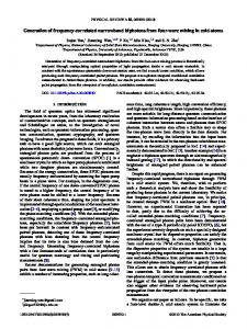
SIMULATION RESULTS:
Fig 3: shows ergodic capacity with for Rayleigh fading channel[8] For efficient deployment of LTE, performance analyses of different radio parameters are worth investigating. Simulations are necessary to test and optimize algorithms and procedures. In Fig (3) showsergodiccapacity for Rayleigh fading channel.Ergodiccapacity refers to the maximum rate that communication can be achieved, assuming the communication duration is longer enough to experience all channel state. It depends on the number of transmitters and receivers using in antenna And SNR values. If the number of transmitters and receivers increases the ergodic capacity also increases along with change is the SNR value as shown in figure (4).
Fig4: shows ergodic capacity with for Rayleigh Fading channel at SNR=10 dB
ISBN No: 978-93-85100-01-7
117
MITS, Madanapalle
2nd National Conference on Recent Trends in Signal Processing
Fig 5: Cumulative Density Function at 10 dB [8]
Fig (5) shows about Cumulative Density Function at 10dB,Cumulative Density function describes about the probability that a real value random variable with its given probability distribution will be found to have a value less than or equals to its maximum value.it also used to specify the multivariate random variables. If the number of transmitters and receivers increases in antenna the CDF also increases. ANALYSIS OF RESULTS: parame ter
No of anten nas
Ergodic capacity at(SNR=0 dB)in(bits/transmissi on) 4.2
Ergodic capacity at(SNR=10 dB)in(bits/transmissi on) 13.8
4×4 5 MIMO 1×4 5 2.5 5.6 SIMO 4×1 5 1 3 MISO 1×1 5 0.8.5 1 SISO Table2: Analysis of ergodic capacity at SNR=0dB& SNR=10 dB
From the above table5 we can observe the difference of ergodic capacity at the different SNR values and different antennas. Conclusion: This paper has explored the design of 4G mobile phone networks. Bandwidth is big constraint to meet the 4G data rate specification. Higher level of modulation such as 1024 QAM is required for transmitting 1 GB/s rates within 100 MHz bandwidth. The advanced technologies such as MIMO and OFDM help to improve the cell radius. On the other hand, low level modulation can be deployed by allocating 250 MHz bandwidth in 30 GHz to 40 ISBN No: 978-93-85100-01-7
118
MITS, Madanapalle
2nd National Conference on Recent Trends in Signal Processing
GHz frequency band. Due to this reason, fifth generation mobile phone networks are being developed. References: [1] Ericsson white paper. Di_erentiated mobile broadband.www.erisson.com/res/docs/whitepapers/differenciated_mobile_broadband.pdf ,January 2011. [2] TeroIsotalo Indoor Planning in Broadband Cellular RadioNetworks.https___dspace.cc.tut.fi_dpub_bitstream_handle_123456789_21321_isot alo [3] White paper on Nokia Siemens Networks performance analysis of Qos in LTE-Advanced Heterogeneous Networks [4] Motorola White Paper on .Long Term Evolution (LTE), A technical overview, 2007. [5] Cisco White Paper. Cisco visual networking index: Global mobile data tra_c forecast update,2011 [6] Cisco visual networking index: global mobile data traffic forecast update 2011016,Cisco,2012 [7] Millimeter wave Wireless Communications: The Renaissance of Computing and Communicationsfaculty.poly.edu_~tsr_keynote. [8] personal.ee.surrey.ac.uk_Personal_T.Brown_MIMObook_Fig215_ErgodicCapacityVsNu mberOfAntennas
ISBN No: 978-93-85100-01-7
119
MITS, Madanapalle