The main advantage of electric traction is a higher power-to-weight ratio than
forms of ... world, and the list of current systems for electric rail traction covers
both ...
First Edition, 2012
ISBN 978-81-323-4395-0
© All rights reserved.
Published by: White Word Publications 4735/22 Prakashdeep Bldg, Ansari Road, Darya Ganj, Delhi - 110002 Email:
[email protected]
Table of Contents Chapter 1 - Railway Electrification System Chapter 2 - Traction Power Network Chapter 3 - Railway Electric Traction Chapter 4 - Electric Locomotive Chapter 5 - Pantograph (Rail) Chapter 6 - Electric Multiple Unit Chapter 7 - Trolley Pole Chapter 8 - Third Rail Chapter 9 - Overhead Lines Chapter 10 - Ground-Level Power Supply
Chapter 1
Railway Electrification System
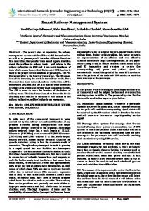
Electric locomotives under the wires in Sweden
Overhead wire and catenary in Bridgeport, Connecticut, United States A railway electrification system supplies electrical energy to railway locomotives and multiple units so that they can operate without having an on-board prime mover. There are several different electrification systems in use throughout the world. Railway electrification has many advantages but requires significant capital expenditure for installation.
Characteristics of electric traction The main advantage of electric traction is a higher power-to-weight ratio than forms of traction such as diesel or steam that generate power on board. Electricity enables faster acceleration and higher tractive effort on steep gradients. On locomotives equipped with regenerative brakes, descending gradients require very little use of air brakes as the locomotive's traction motors become generators sending current back into the supply system and/or on-board resistors, which convert the excess energy to heat. Other advantages include the lack of exhaust fumes at point of use, less noise and lower maintenance requirements of the traction units. Given sufficient traffic density, electric trains produce fewer carbon emissions than diesel trains, especially in countries where electricity comes primarily from non-fossil sources.
A fully electrified railway has no need to switch between methods of traction thereby making operations more efficient. Two countries that approach this ideal are Switzerland and Hong Kong, but both use more than one system, so unless multi-system locomotives or other rolling stock is used, a switch of traction method may still be required. The main disadvantages are the capital cost of the electrification equipment, most significantly for long distance lines which do not generate heavy traffic. Suburban railways with closely-spaced stations and high traffic density are the most likely to be electrified and main lines carrying heavy and frequent traffic are also electrified in many countries. Also, if the overhead wiring breaks down in some way, all trains can be brought to a standstill.
Classification
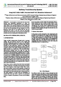
Electrification systems in Europe: non-electrified 750 V DC 1.5 kV DC 3 kV DC 15 kV AC 25 kV AC 1) High speed lines in France, Spain, Italy, United Kingdom, the Netherlands, Belgium and Turkey operate under 25 kV.
Electrification systems are classified by three main parameters:
Voltage Current o Direct current (DC) o Alternating current (AC) Frequency
Contact System o third rail o overhead line (catenary)
Standardised voltages Six of the most commonly used voltages have been selected for European and international standardisation. These are independent of the contact system used, so that, for example, 750V DC may be used with either third rail or overhead lines (the latter normally by trams). There are many other voltage systems used for railway electrification systems around the world, and the list of current systems for electric rail traction covers both standard voltage and non-standard voltage systems. The permissible range of voltages allowed for the standardised voltages is as stated in standards BS EN 50163 and IEC 60850. These take into account the number of trains drawing current and their distance from the substation. Lowest nonElectrification system permanent voltage 600 V DC 400 V 750 V DC 500 V 1,500 V DC 1,000 V 3 kV DC 2 kV 15 kV AC, 11 kV 16.7 Hz 25 kV AC, 17.5 kV 50 Hz
400 V 500 V 1,000 V 2 kV
600 V 750 V 1,500 V 3 kV
Highest Highest nonpermanent permanent voltage voltage 720 V 800 V 900 V 1 kV 1,800 V 1,950 V 3 kV 3 kV
12 kV
15 kV
17.25 kV
18 kV
19 kV
25 kV
27.5 kV
29 kV
Lowest permanent voltage
Nominal voltage
Direct current Early electric systems used low-voltage DC. Electric motors were fed directly from the traction supply and were controlled using a combination of resistors and relays that connected the motors in parallel or series.
The most common DC voltages are 600 V and 750 V for trams and metros and 1,500 V, 650/750 V third rail for the former Southern Region of the UK and 3 kV overhead. The lower voltages are often used with third or fourth rail systems, whereas voltages above 1 kV are normally limited to overhead wiring for safety reasons. Suburban trains (SBahn) lines in Hamburg, Germany, operate using a third rail with 1,200 V, the French SNCF Culoz-Modane line in the Alps used 1,500 V and a third rail until 1976, when a catenary was installed and the third rail was removed. In the UK, south of London, 750 V third rail is used while, for inner London, 650 V is used to allow inter-running with London Underground which uses a 650 V fourth rail system but with the 4th (centre) rail connected to the running rails in inter-running areas. During the mid-20th century, rotary converters or mercury arc rectifiers were used to convert utility (mains) AC power to the required DC voltage at feeder stations. Today, this is usually done by semiconductor rectifiers after stepping down the voltage from the utility supply. The DC system is quite simple but it requires thick cables and short distances between feeder stations because of the high currents required. There are also significant resistive losses. In the United Kingdom, the maximum current that can be drawn by a train is 6,800 A at 750 V. The feeder stations require constant monitoring and, on many systems, only one train or locomotive is allowed per section. The distance between two feeder stations at 750 V on third-rail systems is about 2.5 km (1.6 mi). The distance between two feeder stations at 3 kV is about 25 km (16 mi). If auxiliary machinery, such as fans and compressors, is powered by motors fed directly from the traction supply, they may be larger because of the extra insulation required for the relatively high operating voltage. Alternatively, they can be powered from a motorgenerator set, which offers an alternative way of powering incandescent lights which otherwise would have to be connected as series strings (bulbs designed to operate at traction voltages being particularly inefficient). Now solid-state converters (SIVs) and fluorescent lights can be used.
Overhead systems
The Tyne and Wear Metro is the only United Kingdom system that uses 1,500 V DC. 1,500 V DC is used in the Netherlands, Japan, Hong Kong (parts), Ireland, Australia (parts), India (around the Mumbai area alone, to be converted to 25 kV AC like the rest of the country), France, New Zealand (Wellington) and the United States (Chicago area on the Metra Electric district and the South Shore Line interurban line). In Slovakia, there are two narrow-gauge lines in the High Tatras (one a cog railway). In Portugal, it is used in the Cascais Line and, in Denmark, on the suburban S-train system.
Nottingham Express Transit in United Kingdom uses a 750 V DC overhead, in common with most modern tram systems. In the United Kingdom, 1,500 V DC was used in 1954 for the Woodhead trans-Pennine route (now closed); the system used regenerative braking, allowing for transfer of energy between climbing and descending trains on the steep approaches to the tunnel. The system was also used for suburban electrification in East London and Manchester, now converted to 25 kV AC. 3 kV DC is used in Belgium, Italy, Spain, Poland, the northern Czech Republic, Slovakia, Slovenia, western Croatia, South Africa and former Soviet Union countries (also using 25 kV 50 Hz AC). It was also formerly used by the Milwaukee Road's extensive electrification across the Continental Divide and by the Delaware, Lackawanna & Western Railroad (now New Jersey Transit, converted to 25 kV AC) in the United States. 600 V DC is used by Milan's network of tramways and trolleybuses.
Third rail
A bottom-contact third rail on the Amsterdam Metro, the Netherlands Most electrification systems use overhead wires, but third rail is an option up to about 1,200 V. While use of a third rail does not require the use of DC, in practice, all third-rail systems use DC because it can carry 41% more power than an AC system operating at the same peak voltage. Third rail is more compact than overhead wires and can be used in smaller-diameter tunnels, an important factor for subway systems. Third rail systems can be designed to use top contact, side contact or bottom contact. Top contact is less safe, as the live rail is exposed to people treading on the rail unless an insulating hood is provided. Side- and bottom-contact third rail can easily have safety shields incorporated, carried by the rail itself. Uncovered top-contact third rails are vulnerable to disruption caused by ice, snow and fallen leaves. DC systems (especially third rail systems) are limited to relatively low voltages and this can limit the size and speed of trains and cannot use low-level platform and also limit the amount of air-conditioning that the trains can provide. This may be a factor favouring overhead wires and high voltage AC, even for urban usage. In practice, the top speed of trains on third-rail systems is limited to 100 mph (160 km/h) because, above that speed, reliable contact between the shoe and the rail cannot be maintained. Some road operating trams (streetcars) used conduit third-rail current collection. The third rail was below street level. The tram picked up the current through a plough (U.S. "plow") accessed through a narrow slot in the road. In the United States, much (though not all) of the former streetcar system system in Washington, D.C. (discontinued in 1962) was operated in this manner to avoid the unsightly wires and poles associated with electric traction. The same was true with Manhattan's former streetcar system. The evidence of this mode of running can still be seen on the track down the slope on the northern access to the abandoned Kingsway Tramway Subway (in central London,
United Kingdom), where the slot between the running rails is clearly visible, and on P and Q Streets west of Wisconsin Avenue in the Georgetown neighborhood of Washington DC, where the abandoned tracks have not been paved over. The slot can easily be confused with the similar looking slot for cable trams/cars (indeed, in some cases, the conduit slot was originally a cable slot). The disadvantage of conduit collection included much higher initial installation costs, higher maintenance costs, and problems with leaves and snow getting in the slot. For this reason, in Washington, D.C. cars on some lines converted to overhead cable on leaving the city center, a worker in a "plow pit" disconnecting the plow while another raised the trolley pole (hitherto hooked down to the roof) to the now-present overhead wire. In New York City for the same reasons of cost and operating efficiency outside of Manhattan overhead wire was used. Finally, a new approach to avoiding overhead wires is that taken by the "second generation" tram/streetcar system in Bordeaux, France (entry into service of the first line in December 2003; original system discontinued in 1958)with its APS (alimentation par sol -- ground current feed). This involves a third rail which is not in a slot but runs flush with the surface like the tops of the running rails. The circuit is divided into segments with each segment energized in turn by sensors from the car as it passes over it, the remainder of the third rail remaining "dead". Since each energized segment is completely covered by the lengthy articulated cars, and goes dead before being "uncovered" by the passage of the vehicle, there is no danger to pedestrians. At least initially there were teething troubles in terms of maintaining current feed, however, and the fact that the system is used exclusively in the historic center, with the cars on leaving this zone converting to conventional overhead pickup, underlines how, esthetics aside, for streetcars/trams it is hard to beat the overhead wire system in terms of overall efficiency.
Fourth rail
Arcs like this are normal and occur when the collection shoes of a train drawing power reach the end of a section of power rail.
With top-contact third (and fourth) rail a heavy shoe suspended from a wooden beam attached to the bogies collects power by sliding over the top surface of the conductor rail. The London Underground in England is one of the few networks that uses a four-rail system. The additional rail carries the electrical return that, on third rail and overhead networks, is provided by the running rails. On the London Underground, a top-contact third rail is beside the track, energized at +420 V DC and a top-contact fourth rail is located centrally between the running rails at −210 V DC, which combine to provide a traction voltage of 630 V DC. The same system was used for Milan's earliest underground line, Milan Metro's line 1, whose more recent lines use an overhead catenary. This scheme was introduced because of the problems of return currents, intended to be carried by the earthed (grounded) running rails, flowing through the iron tunnel linings instead. This can cause electrolytic damage and even arcing if the tunnel segments are not electrically bonded together. The problem was exacerbated because the return current also had a tendency to flow through nearby iron pipes forming the water and gas mains. Some of these, particularly Victorian mains that predated London's underground railways, were never constructed to carry currents and had no adequate electrical bonding between pipe segments. The four-rail system solves the problem. Although the supply has an artificially created earth point, this connection is derived by using resistors which ensures that stray earth currents are kept to manageable levels.
London Underground track at Ealing Common on the District Line, showing the third and fourth rails beside and between the running rails London's sub-surface underground railways also operate on the four-rail scheme since, in a number of areas (for example the Piccadilly Line and Metropolitan Line services to Uxbridge), sub-surface and deep-level stock run on the same tracks. On lines shared with National Rail third-rail stock, the centre 'negative' rail is connected to the return running rail, allowing both types of train to operate. A system proposed (but not used) by the South Eastern and Chatham Railway around 1920 was 1,500 V DC four-rail. Technical details are scarce but it is likely that it would have been a mid-earth system with one conductor rail at +750 volts and the other at −750 volts. This would have facilitated conversion to 750 V DC three-rail at a later date. A few lines of the Paris Métro in France also operate on a four-rail power scheme but for a very different reason. It is not strictly a four-rail scheme as they run on natural rubber tyres running on a pair of narrow roadways made of steel and, in some places, concrete. Since the tyres do not conduct the return current, two conductor rails are provided outside of the running 'roadways', so at least electrically it fits as a four-rail scheme. The trains are designed to operate from either polarity of supply, because some lines use reversing loops at one end, causing the train to be reversed during every complete journey
(intended to save having to "change ends" by having the operator walk to the other end of the train to make the former last car the lead car in the new direction).
Alternating current These are overhead electrification systems. Alternating current can be transformed to lower voltages inside the locomotive. This allows much higher voltages and therefore smaller currents along the line, which means smaller energy losses along long railways.
Low-frequency alternating current
15 kV 16.7 Hz AC traction current used in Switzerland
The world's first AC locomotive in Valtellina (1898–1902). Power supply: 3-phase 15 Hz AC, 3000 V, (AC motor 70 km/h). It was designed by Kálmán Kandó in Ganz Company, Hungary. Common DC commutating electric motors can also be fed with AC (universal motor), because reversing the current in both stator and rotor does not change the direction of torque. However, the inductance of the windings made early designs of large motors impractical at standard AC distribution frequencies. In addition, AC induces eddy currents, particularly in non-laminated field pole pieces, that cause overheating and loss of efficiency. In the previous century, five European countries, including Germany, Austria, Switzerland, Norway and Sweden, standardized on 15 kV 16⅔ Hz (one-third of the normal mains frequency) single-phase AC in an attempt to alleviate such problems. On 16 October 1995, Germany, Austria and Switzerland changed the designation from 16⅔ Hz to a nominal frequency of 16.7 Hz (though the actual frequency has not changed, its designation has). In the United States (with its 60 Hz distribution system), 25 Hz (an older, now-obsolete standard mains frequency) is used at 11 kV between Washington, D.C. and New York City and between Harrisburg, Pennsylvania and Philadelphia. A 12,500 V 25 Hz section between New York City and New Haven, Connecticut was converted to 60 Hz in the last third of the 20th century. In the UK, the London, Brighton and South Coast Railway pioneered overhead electrification of its suburban lines in London, London Bridge to Victoria being opened to traffic on 1 December 1909. Victoria to Crystal Palace via Balham and West Norwood opened in May 1911. Peckham Rye to West Norwood opened in June 1912. Further extensions were not made owing to the First World War. Two lines opened in 1925 under the Southern Railway serving Coulsdon North and Sutton railway station. The lines were
electrified at 6.7 kV 25 Hz. It was announced in 1926 that all lines were to be converted to DC third rail and the last overhead electric service ran in September 1929. In such a system, the traction motors can be fed through a transformer with multiple taps. Changing the taps allows the motor voltage to be changed without requiring powerwasting resistors. Auxiliary machinery is driven by small commutating motors powered from a separate low-voltage winding of the main transformer. The use of low frequency requires that electricity be converted from utility power by motor-generators or static inverters at the feeding substations, or generated at altogether separate traction powerstations. Since 1979, the three-phase induction motor has become almost universally used. It is fed by a static four-quadrant converter which supplies a constant voltage to a pulse-width modulator inverter that supplies the three-phase variable frequency to the motors.
Polyphase alternating current systems
3 phase pantograph on a Corcovado Rack Railway train in Brazil
Train using a multiphase electrification system on the Petit train de la Rhune, France The majority of the Italian State railway system three-phase system was 3,300 V at 15– 16.7 Hz. With such a low frequency, the locomotives did not need gearing. It is also possible to use the polyphase system regeneratively, as on the Italian State railway's mountain lines, where a loaded train descending could supply much of the power for a train ascending. Experimental polyphase installations in Italy in the 1930s used higher voltage (10 kV) at industrial frequencies (45 or 50 Hz). In the United States, the Great Northern Railway's (Cascade Tunnel) first electrified line (1909–1927) was at 6,600 V, 25 Hz. The main complexity with three-phase systems is the need for three conductors (including the rails), hence two overhead conductors. Early locomotives on the Italian State Railways used a wide bow collector which covered both wires but later locomotives used two pantographs side-by-side. In the United States, a pair of trolley poles were used.
They worked well with a maximum speed limit of 15 mph. The dual conductor pantograph system is used on four mountain railways that continue to use three phase power (Corcovado Rack Railway in Rio de Janeiro, Brazil, Jungfraubahn and Gornergratbahn in Switzerland and the Petit train de la Rhune in France).
Standard frequency alternating current Only in the 1950s after development in France (20 kV then 25 kV) and former Soviet Union countries (25 kV) did the standard-frequency single-phase alternating current system become widespread, despite the simplification of a distribution system which could use the existing power supply network. The first attempts to use standard-frequency single-phase AC were made in Hungary since 1923, by the Hungarian Kálmán Kandó on the line between Budapest-Nyugati and Alag, using 16 kV at 50 Hz. The locomotives carried a four-pole rotating phase converter feeding a single traction motor of the polyphase induction type at 600 to 1,100 V. The number of poles on the 2,500 hp motor could be changed using slip rings to run at one of four synchronous speeds. The tests were a success so, from 1932 until 1960s, trains on the Budapest-Hegyeshalom line (towards Vienna) regularly used the same system. A few decades after the second world war, the 16 kV was changed to the Russian and later French 25 kV system. Today, some locomotives in this system use a transformer and rectifier to provide lowvoltage pulsating direct current to motors. Speed is controlled by switching winding taps on the transformer. More sophisticated locomotives use thyristor or IGBT circuitry to generate chopped or even variable-frequency alternating current (AC) that is then supplied to the AC induction traction motors. This system is quite economical but it has its drawbacks: the phases of the external power system are loaded unequally and there is significant electromagnetic interference generated as well as significant acoustic noise. A list of the countries using the 25 kV AC 50 Hz single-phase system can be found in the list of current systems for electric rail traction.
Close-up view of catenary on Northeast Corridor, United States The United States commonly uses 12.5 and 25 kV at 25 Hz or 60 Hz. 25 kV, 60 Hz AC is the preferred system for new high-speed and long-distance railways, even if the railway uses a different system for existing trains. To prevent the risk of out-of-phase supplies mixing, sections of line fed from different feeder stations must be kept strictly isolated. This is achieved by Neutral Sections (also known as Phase Breaks), usually provided at feeder stations and midway between them although, typically, only half are in use at any time, the others being provided to allow a feeder station to be shut down and power provided from adjacent feeder stations. Neutral Sections usually consist of an earthed section of wire which is separated from the live wires on either side by insulating material, typically ceramic beads, designed so that the pantograph will smoothly run from one section to the other. The earthed section prevents an arc being drawn from one live section to the other, as the voltage difference may be higher than the normal system voltage if the live sections are on different phases and the protective circuit breakers may not be able to safely interrupt the considerable current that would flow. To prevent the risk of an arc being drawn across from one section of wire to earth, when passing through the neutral section, the train must be coasting and the circuit breakers must be open. In many cases, this is done manually by the driver. To help them, a warning board is provided just before both the neutral section and an advanced warning some distance before. A further board is then provided after the neutral section
to tell the driver to re-close the circuit breaker, although the driver must not do this until the rear pantograph has passed this board. In the UK, a system known as Automatic Power Control (APC) automatically opens and closes the circuit breaker, this being achieved by using sets of permanent magnets alongside the track communicating with a detector on the train. The only action needed by the driver is to shut off power and coast and therefore warning boards are still provided at and on the approach to neutral sections. On French high-speed rail lines, the UK High Speed 1 Channel Tunnel rail link and in the Channel Tunnel itself, neutral sections are negotiated automatically.
World electrification
Railway electrification in Europe by country In 2006, 240,000 km (25% by length) of the world rail network was electrified and 50% of all rail transport was carried by electric traction.
Advantages and disadvantages Advantages include:
lower running cost of locomotives and multiple units lower maintenance cost of locomotives and multiple units higher power-to-weight ratio, resulting in o fewer locomotives o faster acceleration
higher practical limit of power higher limit of speed less noise pollution (quieter operation) reduced power loss at higher altitudes lack of dependence on crude oil as fuel less environmental pollution, even if electricity is produced by fossil fuels o o
Disadvantages include:
Large cargo may require special cars
upgrading brings significant cost, o especially where tunnels and bridges and other obstructions have to be altered for clearance o alterations or upgrades will be needed on the railway signalling to take advantage of the new traffic characteristics
Trade-offs include:
Maintenance costs of the lines may be increased, but many systems claim lower costs due to reduced wear-and-tear from lighter rolling stock. There are additional maintenance costs associated with the electrical equipment but, if there is sufficient traffic, reduced track and engine maintenance costs can exceed the costs of this maintenance.
Most overhead electrifications do not allow sufficient clearance for a double-stack car.
Network effects are a large factor with electrification. When converting lines to electric, the connections with other lines must be considered. Some electrifications have eventually been removed because of the through traffic to non-electrified lines. If through traffic is to have any benefit, time consuming engine switches must occur to make such connections or expensive dual mode engines must be used. This is mostly an issue for long distance trips, but many lines come to be dominated by through traffic from long-haul freight trains (usually running coal, ore, or containers to or from ports). In theory, these trains could enjoy dramatic savings through electrification, but it can be too costly to extend electrification to isolated areas, and unless an entire network is electrified, companies often find that they need to continue use of diesel trains even if sections are electrified. The increasing demand for container traffic which is more efficient when utilizing the double-stack car also has network effect issues with existing electrifications due to insufficient clearance of overhead electrical lines for these trains, but electrification can be built or modified to have sufficient clearance, at additional cost.
Additionally, there are issues of connections between different electrical services, particularly connecting intercity lines with sections electrified for commuter traffic, but also between commuter lines built to different standards. This can cause electrification of
certain connections to be very expensive simply because of the implications on the sections it is connecting. Many lines have come to be overlaid with multiple electrification standards for different trains to avoid having to replace the existing rolling stock on those lines. Obviously, this requires that the economics of a particular connection must be more compelling and this has prevented complete electrification of many lines. In a few cases, there are diesel trains running along completely electrified routes and this can be due to incompatibility of electrification standards along the route. Summary of advantages and disadvantages:
Lines with low frequency of traffic may not be feasible for electrification (especially using regenerative braking), because lower running cost of trains may be overcome by the higher costs of maintenance. Therefore most long-distance lines in North America and many developing countries are not electrified due to relatively low frequency of trains. Electric locomotives may easily be constructed with greater power output than most diesel locomotives. For passenger operation it is possible to provide enough power with diesel engines but, at higher speeds, this proves costly and impractical. Therefore, almost all high speed trains are electric. The high power of electric locomotives gives them the ability to pull freight at higher speed over gradients; in mixed traffic conditions this increases capacity when the time between trains can be decreased. The higher power of electric locomotives and an electrification can also be a cheaper alternative to a new and less steep railway if trains weights are to be increased on a system.
Energy efficiency There is a significant amount of published material that concludes that electric trains are more energy efficient than diesel-powered trains and, with suitable energy production, can have a smaller carbon dioxide footprint. Some of the reasons include:
electric trains are generally lighter than self powered versions (eg diesel traction); o they do not have to carry the weight of prime movers, transmission and fuel. o this is partially offset, however, by the weight of electrical control equipment, and in the case with high-voltage AC by the weight of traction transformers, which may be particularly heavy with low frequency AC (e.g. 16.7 Hz.).
the electricity may be generated from various energy sources which are more efficient than a diesel engine, as well as lessening reliance on petroleum products and reducing carbon dioxide emmissions, including; o nuclear power, o renewable resources (e.g. hydroelectricity, wind generation, etc.), o large fossil fuel using power stations with greater efficiency (although they may still have a relatively large carbon footprint).
under certain conditions, some suitably equipped electric trains can use regenerative braking to return power to the electrification system so that it may be used elsewhere; o by other vehicles within the network section; often implemented in tram networks, where there is a high density of vehicles in each fairly short powered section, on high voltage mainlines where there may be several trains within each long section, on mountainous lines where trains may be scheduled such that one is ascending whilst another descends; o in some form of energy storage, such as flywheel energy storage so that it may be used later (eg to accelerate a train from a station at which it has recently stopped) o some systems, such as most 25 kV AC systems in the UK, are able to return excess energy to the public network.
According to widely accepted global energy reserve statistics, the reserves of liquid fuel are much less than gas and coal (at 42, 167 and 416 years respectively). Most countries with large rail networks do not have significant oil reserves and those that did, like the United States and Britain, have exhausted much of their reserves and have suffered declining oil output for decades. Therefore, there is also a strong economic incentive to substitute oil for other fuels. Rail electrification is often considered an important route towards consumption pattern reform.
External cost The external cost of railway is lower than other modes of transport but the electrification brings it down further if it is sustainable. Also, the lower cost of energy from well to wheel and the ability to reduce pollution and greenhouse gas in the atmosphere according to the Kyoto Protocol is an advantage.
Research and development Another result of electrification is the effect on locomotive and wagon productivity and it is going to be more effective by more railway research in this field. The trend of technology in railway electrification is very important to adopt the efforts for better results, for example the trend from GTO (Gate turn-off thyristor) to IGBT (Insulated-gate bipolar transistor) for more powerful locomotives with higher reliability is one of the elements of Technology roadmap (TRM) and the loop to have a mature system as in Maturity road mapping with the Technology transfer provision.
Chapter 2
Traction Power Network
Twisting pylon of power line for single-phase AC traction current (110 kV, 16⅔ Hz) near Bartholomä in Germany. A traction network or traction power network is an electricity grid for the supply of electrified rail networks. The installation of a separate traction network generally is only
done if the railway in question uses alternating current (AC) with a frequency lower than that of the national grid, such as in Germany, Austria and Switzerland. Alternatively, the three-phase alternating current of the power grid can be converted in substations by rotary transformers or static inverters into the voltage and type of current required by the trains. For railways which run on direct current (DC), this method is always used, as well as for railways which run on single-phase AC of decreased frequency, as in Mecklenburg-Western Pomerania, Saxony-Anhalt, Norway and Sweden. In these areas there are no traction current networks.
History Separate power for traction apart from industrial power always has historic roots. There is no reason today to apply different frequencies or current types than for transmission and for industrial usage. However, the advantage with DC traction was the easier transmission with single copper wires to the feeder points. The advantage with AC traction is the easier transmission over long distances to the feeder points. Beyond these parameters and securing former investment, no evidence exists to stay with different current schemes in networks.
Applications Dedicated traction current lines are used when railways are supplied with low frequency alternating current. The traction current supply line is connected to substations along the line of the railway and is usually run separately from the overhead catenary wire from which the locomotives are fed. In countries in which the electric trains run with direct current or with single phase AC current with the frequency of the general power grid, the required conversion of the current is performed in the substations, so again no traction current lines are required. Traction current supply lines are not usually laid parallel to the railway line, in order to allow a shorter line length and to avoid unnecessary influences to the electrical system near the railway line; this also is applied to the current supply of some rapid-transit railways operating with alternating current in Germany. It is also possible to lay out the traction current supply on special cross beams right on the overhead wire pylons above the catenary wire. Because the overhead line pylons have a smaller cross section than traction current supply masts the cross beams cannot be too wide, so the standard arrangement of four conductor cables in one level cannot be used. In this case a two-level arrangement is used, or with two electric circuits for double-railed lines the overhead line pylons for both directions are equipped with cross beams for their own traction current system of two conductor cables each. In densely populated areas there are pylons, which carry circuits for both traction current and for three-phase alternating current for general power. Such lines are found where
right of ways are rare. In particular the parallel route of 110 kV and 220 kV three-phase AC is common. The use of 380 kV-power lines on the same pylon requires 220 kV insulators for the traction current line, because in case the 380 kV line fails, voltage spikes can occur along the traction current line, which the 110 kV insulators cannot handle. As a rule traction current lines use single conductors, however for the supply of railways with high traffic and in particular for the supply of high speed railway lines, two bundle conductors are used.
Around the World Austria The Mariazeller railway in Lower Austria operates on single phase AC at a 25 Hz utility frequency. The railway has its own traction current lines with an operating voltage of 27 kV. These lines are mounted on the pylons of the overhead wire over the catenary wire.
Germany In Germany, single conductors are usually used for traction current lines but, for the ICE train, two bundle conductors are used. The traction current supply lines from the nuclear power station Neckarwestheim to the traction current switching station at Neckarwestheim and from there to the central substation in Stuttgart, Zazenhausen are implemented as a four-bundle conductor circuit.
Scandinavia In Sweden, Norway and some areas of the former German Democratic Republic, three phase AC-current is converted into single phase AC current with a frequency of 16.7 cycles per second at the substations. Unlike in Germany, there are no dedicated power plants for railway electricity. All power comes from general electricity suppliers. Although in this regions there is, in principle, no requirement for traction power lines, there is a 132 kV-single AC power grid for railway power supply in Central Sweden. In Norway, there is a small 55 kV single phase AC network for power supply of trains in the South, fed by Hakavik Power Station. A further power station, at Kjofossen feeds single phase AC directly in the overhead wire. In Denmark and Finland, 50 Hz is used for the main lines (if electrified) and the electricity comes from general suppliers. As such, much simpler equipment than in Sweden and Norway is needed for conversion.
South Africa In the Republic of South Africa there are extensive AC and DC traction schemes, including 50 kV and 25 kV AC single phase systems. Electrification in Natal was
stimulated by the takeover of the South African Railways' system by the Electricity Supply Commission (now Eskom) based on the Colenso power station.
United Kingdom In the United Kingdom, the Network Rail 750 V DC electrification system in the southeast of England is supplied with power from an extensive 33 kV power distribution network.
Areas with traction power networks
United Kingdom Germany (except Mecklenburg-Western Pomerania and Saxony-Anhalt), total length 7959 km Switzerland Austria (separate traction power network for the Mariazeller Bahn) Central Sweden Southern Norway east of Oslo USA (in New York and Washington DC area for railway lines running with single phase 25 Hz AC, South Africa Melbourne, Australia (dedicated high voltage transmission wires between former Newport A Power Station and traction substations. However these lines are operated with three phase AC)
Chapter 3
Railway Electric Traction
Railway electric traction describes the various types of locomotive and multiple units that are used on electrification systems around the world.
History Railway electrification as a means of traction emerged at the end of the nineteenth century, although experiments in electric rail have been traced back to the mid-nineteenth century . Thomas Davenport, in Brandon, Vermont, erected a circular model railroad on which ran battery-powered locomotives (or locomotives running on battery-powered rails) in 1834. Robert Davidson, of Aberdeen, Scotland, created an electric locomotive in 1839 and ran it on the Edinburgh-Glasgow railway at 4 miles per hour. The earliest electric locomotives tended to be battery-powered. In 1880, Thomas Edison built a small electrical railway, using a dynamo as the motor and the rails as the current-carrying medium. The electric current flowed through the metal rim of otherwise wooden wheels, being picked up via contact brushes. Electrical traction offered several benefits over the then predominant steam traction, particularly in respect of its quick acceleration (ideal for urban (metro) and suburban (commuter) services) and power (ideal for heavy freight trains through mountainous/hilly sections). A plethora of systems emerged in the first twenty years of the twentieth century.
Unit types DC traction units DC traction units use direct current drawn from either a conductor rail or an overhead line.
AC traction units Apart from a few cases, almost all AC Traction units draw alternating current from an overhead line.
Multi-system units Because of the variety of railway electrification systems, which can vary even within a country, trains often have to pass from one system to another. One way to accomplish this is by changing locomotives at the switching stations. These stations have overhead wires that can be switched from one voltage to another and so the train arrives with one locomotive and then departs with another. Often, however, this is inconvenient and timeconsuming. The switching stations have very sophisticated components and they are very expensive. Another way is to use multi-system locomotives that can operate under several different voltages and current types. In Europe, it is common to use four-system locomotives (1.5 kV DC, 3 kV DC, 15 kV 16⅔ Hz AC, 25 kV, 50 Hz AC). These locomotives do not have to stop when passing from one electrification system to another, the changeover occurring where the train coasts for a short time. Eurostar trains through the Channel Tunnel are multisystem; a significant part of the route near London is on southern England's 750 V DC third rail system, the route into Brussels is 3000 V DC overhead, while the rest of the route is 25 kV 50 Hz overhead. The need for these trains to use third rail ended upon completion of High Speed 1 in 2007. Southern England has some overhead/third rail dual-system locomotives and multiple units to allow through running between 750 V DC third rail south of London and the 25 kV AC overhead north and east of London. Electro-diesel locomotives which can operate as an electric locomotive on electrified lines but have an on-board diesel engine for non-electrified sections or sidings have been used in several countries.
Czech Republic and Slovakia In the Czech Republic and Slovakia, the railways have both 3,000 V DC and 25 kV AC systems but there are no switching stations - the two systems meet at breaks on overhead wires. Only two of the breaks (Kutná Hora and Nedakonice) are in stations.
United Kingdom Electrification in the UK began in a piecemeal fashion. The earliest main line (as opposed to metro and tramway) systems were divided between low voltage third rail (commonly about 600 V DC) and overhead systems (a variety of voltages, both DC and AC were used). The third rail systems of this period eventually gave rise to the 750 V DC system
in the southern part of the UK and a separate area with the same system around Merseyside. Cheap loans to stimulate economic development in the 1930s gave rise to the several schemes of 1500 V DC electrification, mostly completed post war, notably between Liverpool Street and Shenfield, and the Woodhead Line. Starting with the West Coast Mainline electrification in the 1960s, the 25 kV AC overhead system was adopted for all subsequent mainline electrification in the UK (except for extensions to other existing systems, mostly on the southern third rail network). In some areas with restricted clearances, particularly in urban areas in east London (converted from 1500 V DC) and on suburban routes around Glasgow, 6.25 kV was used. A system known as "Automatic Power Control" was developed to allow trains to automatically switch between the voltages whilst moving. All the driver had to do was shut off power and coast until clear of the neutral section; the system automatically opened the circuit breaker, detected a change in voltage and switched over the transformer to the correct input voltage setting, then closed the circuit breaker. This system proved somewhat unreliable and, with experience, it was found that less clearance was needed for 25 kV than had initially been allowed for. This allowed the 6.25 kV sections to be converted to 25 kV, with the last section, at the London end of the London Tilbury and Southend line, being converted in 1983.
United States In the United States, New Jersey Transit uses multisystem ALP-44 and ALP-46 locomotives for its Midtown Direct service into New York and Amtrak uses multi-system AEM-7, HHP-8 and Acela locomotives on the Northeast Corridor between Washington DC and Boston. In both cases, through trains run on both newer, 25 kV 60 Hz built or refurbished by their respective agencies since the 1980s and older, 12 kV 25 Hz inherited from the now-defunct Pennsylvania Railroad. The latter dates to the 1930s, when the Pennsylvania upgraded its electrified network from 650 V DC third rail.
Italy Italian railways have two systems with overhead supply from a catenary: 3 kV DC and 25 kV AC. The 25 kV AC system is used on the new High speed lines.
Spain Spanish railways have two systems with overhead supply from a catenary: 3 kV DC and 25 kV AC. The 25 kV AC system is used on the High speed lines.
India In India 1500 V DC and 25 kV AC, 50 Hz, is used for main line trains.
The 1500 V DC overhead system (negative earth, positive catenary) is used around Mumbai. The Mumbai region is the last bastion of 1500 V DC electrified lines on Indian Railways. There are plans to change this to 25 kV AC by 2010. The 25 kV AC system with overhead lines is used throughout the rest of the country. The dual-voltage WCAM series locomotives haul intercity trains out of Mumbai DC suburban region. The new AC/DC EMU rakes used in Mumbai are also designed to operate with both DC and AC traction as the Mumbai area switches over to the 25 kV AC system. The Kolkata Metro uses 750 V DC traction with a third rail for delivering the electricity to the EMUs. The Kolkata trams use 550 V DC with overhead lines with underground conductors. The catenary is at a negative potential. The Delhi Metro uses 25 kV AC overhead lines on the ground-level and elevated routes, and uses a rather unusual "rigid catenary", or overhead power rail, in the underground tunnel sections.
South Africa South Africa has 15 km of dual system track, both 3 kV DC and 25 kV AC.
Battery electric rail vehicles A few battery electric railcars and locomotives were used in the twentieth century, but generally the use of battery power was not practical except in underground mining systems.
High-speed rail Many high-speed rail systems use electric trains, like the Shinkansen and the TGV.
Chapter 4
Electric Locomotive
Indian Locomotive Class Wap 5 hauling the Bhopal Shatabdi Express to New Delhi
Deutsche Bahn DBAG Class 152 pulling a freight train
New Jersey Transit ALP-46 AC locomotive based on the DBAG Class 101 An electric locomotive is a locomotive powered by electricity from overhead lines, a third rail or an on-board energy storage device (such as a chemical battery or fuel cell). Electrically propelled locomotives with on-board fuelled prime movers, such as diesel engines or gas turbines, are classed as diesel-electric or gas turbine electric locomotives because the electric generator/motor combination only serves as a power transmission system. Electricity is used to eliminate smoke and take advantage of the high efficiency of electric motors; however, the cost of railway electrification means that usually only heavily-used lines can be electrified.
Characteristics One advantage of electrification is the lack of pollution from the locomotives themselves. Electrification also results in higher performance, lower maintenance costs and lower energy costs for electric locomotives. Power plants, even if they burn fossil fuels, are far cleaner than mobile sources such as locomotive engines. Also the power for electric locomotives can come from clean and/or renewable sources, including geothermal power, hydroelectric power, nuclear power, solar power and wind turbines. Electric locomotives are also quiet compared to diesel locomotives since there is no engine and exhaust noise and less mechanical noise. The
lack of reciprocating parts means that electric locomotives are easier on the track, reducing track maintenance. Power plant capacity is far greater than what any individual locomotive uses, so electric locomotives can have a higher power output than diesel locomotives and they can produce even higher short-term surge power for fast acceleration. Electric locomotives are ideal for commuter rail service with frequent stops. They are used on high-speed lines, such as ICE in Germany, Acela in the US, Shinkansen in Japan, China Railway High-speed in China and TGV in France. Electric locomotives are also used on freight routes that have a consistently high traffic volume, or in areas with advanced rail networks. Electric locomotives benefit from the high efficiency of electric motors, often above 90%. Additional efficiency can be gained from regenerative braking, which allows kinetic energy to be recovered during braking to put some power back on the line. Newer electric locomotives use AC motor-inverter drive systems that provide for regenerative braking. The chief disadvantage of electrification is the cost for infrastructure (overhead power lines or electrified third rail, substations, control systems). Public policy in the US currently interferes with electrification—higher property taxes are imposed on privately owned rail facilities if they have electrification facilities. Also, US regulations on diesel locomotives are very weak compared to regulations on automobile emissions or power plant emissions. In Europe and elsewhere, railway networks are considered part of the national transport infrastructure, just like roads, highways and waterways, and therefore are often financed by the state. Operators of the rolling stock pay fees according to rail use. This makes possible the large investments required for the technically and in the long-term also, economically advantageous electrification. Because railroad infrastructure is privately owned in the US, railroads are unwilling to make the necessary investments for electrification.
History
Electric locomotive of the Baltimore Belt Line, 1895. The steam locomotive was not detached for passage through the tunnel. The overhead conductor was a ∩ section bar at the highest point in the roof, so a flexible, flat pantograph was used
Alco-GE Prototype Class S-1, NYC & HR no. 6000 (DC)
AC locomotive in Valtellina (1898-1902). Power supply: 3-phase 15 Hz AC, 3000 V. Designed by Kálmán Kandó in Ganz Company, Hungary and supplied by Westinghouse.
A GE steeplecab electric locomotive. This example is fitted with trolley poles for service on an interurban railroad.
A Milwaukee Road class ES-2, an example of a larger steeplecab switcher for service on an electrified heavy-duty railroad The first known electric locomotive was built by a Scotsman, Robert Davidson of Aberdeen in 1837 and was powered by galvanic cells ('batteries'). Davidson later built a larger locomotive named Galvani which was exhibited at the Royal Scottish Society of Arts Exhibition in 1841. It was tested on the Edinburgh and Glasgow Railway in September of the following year but the limited electric power available from batteries prevented its general use. The first electric passenger train was presented by Werner von Siemens at Berlin in 1879. The locomotive was driven by a 2.2 kW motor and the train, consisting of the locomotive and three cars, reached a maximum speed of 13 km/h. During four months, the train carried 90,000 passengers on a 300 metre long circular track. The electricity was supplied through a third, insulated rail situated between the
tracks. A stationary dynamo nearby provided the electricity. The world's first electric tram line opened in Lichterfelde near Berlin, Germany, in 1881. It was built by Werner von Siemens. In Britain, Volk's electric railway was opened in 1883 in Brighton. In the US, electric trolleys were pioneered in 1888 on the Richmond Union Passenger Railway, using equipment designed by Frank J. Sprague. Much of the early development of electric locomotion was driven by the increasing use of tunnels, particularly in urban areas. Smoke from steam locomotives was noxious and municipalities were increasingly inclined to prohibit their use within their limits. Thus the first successful working, the City and South London Railway underground line in the UK, was prompted by a clause in its enabling act prohibiting use of steam power. This line opened in 1890, using electric locomotives built by Mather and Platt. Electricity quickly became the power supply of choice for subways, abetted by the Sprague's invention of multiple-unit train control in 1897. Surface and elevated rapid transit systems generally used steam until forced to convert by ordinance. The first use of electrification on a mainline was on a four-mile stretch of the Baltimore Belt Line of the Baltimore and Ohio Railroad (B&O) in 1895. This track connected the main portion of the B&O to the newly built line to New York and it required a series of tunnels around the edges of Baltimore's downtown. Parallel tracks on the Pennsylvania Railroad had shown that coal smoke from steam locomotives would be a major operating issue, as well as a public nuisance. Three Bo+Bo units were initially used, at the south end of the electrified section; they coupled onto the entire train, locomotive and all and pulled it through the tunnels. Railroad entrances to New York City required similar tunnels and the smoke problems were more acute there. A collision in the Park Avenue tunnel in 1902 led the New York State legislature to outlaw the use of smoke-generating locomotives south of the Harlem River after 1 July 1908. In response, electric locomotives began operation in 1904 on the New York Central Railroad. In the 1930s, the Pennsylvania Railroad, which also had introduced electric locomotives because of the NYC regulation, electrified its entire territory east of Harrisburg, Pennsylvania.
Introduction of alternating current The first practical AC electric locomotive was designed by Charles Brown, then working for Oerlikon, Zürich. In 1891, Brown had demonstrated long-distance power transmission, using three-phase AC, between a hydro-electric plant at Lauffen am Neckar and Frankfurt am Main West railway station, a distance of 280 km. Brown, using the experience he had gained while working for Jean Heilmann on steam-electric locomotive designs, had observed that three-phase motors had a higher power-to-weight ratio than DC motors and, because of the absence of a commutator, were simpler to manufacture and maintain. However, they were much larger than the DC motors of the time and could not be mounted in underfloor bogies: they could only be carried within locomotive bodies. In 1896, Oerlikon installed the first commercial example of the system on the Lugano Tramway. Three-phase motors, which run at constant speed and provide regenerative braking, are well suited to steeply graded routes and the first mainline threephase locomotives were installed by Brown (by then in partnership with Walter Boveri)
in 1899 on the Burgdorf—Thun line, Switzerland. Each thirty-tonne locomotive had two 150 h.p. motors. A development by Kálmán Kandó of the Ganz works, Budapest, working with Westinghouse of Italy, introduced an electro-mechanical converter, allowing the use of three-phase motors powered from single-phase alternating current, thus eliminating the need for two overhead conductor wires. The first implementation of industrial frequency single-phase AC supply for locomotives came from Oerlikon in 1901, using the designs of Hans Behn-Eschenburg and Emil Huber-Stockar; installation on the Seebach-Wettingen line of the Swiss Federal Railways was completed in 1904. The 15 kV, 50 Hz 345 kilowatts (460 hp), 48 tonne locomotives used transformers and rotary converters to power DC traction motors. Italian railways were the first in the world to introduce electric traction for the entire length of a mainline rather than just a short stretch, using a system from Westinghouse, designed by Kálmán Kandó and a team from the Ganz works. The 106 km Valtellina line was opened on 4 September 1902. The electrical system was three-phase at 3 kV 15 Hz. The converter transformed single-phase current into three-phase alternating current within the locomotive. The voltage was significantly higher than used earlier and it required new designs for electric motors and switching devices. During the period of electrification of the Italian railways, some tests were made as to which type of power supply to use: in some sections there was a 3,600 V 16⅔ Hz three-phase power supply, in others there was 1,500 V DC, 3 kV DC and 10 kV AC 50Hz supply. During the 1930s, 3kV DC power was chosen for the entire Italian railway system. (Nowadays, 1,500 V DC is still used on some lines near France and 25kV 50Hz is used on high speed trains) Kandó designed a three phase AC traction in Evian Les Bains (Switzerland) in 1898. In the United States, the Chicago, Milwaukee, St. Paul and Pacific Railroad (the Milwaukee Road), the last transcontinental line to be built, electrified its lines across the Rocky Mountains and to the Pacific Ocean starting in 1915. A few East Coast lines, notably the Virginian Railway and the Norfolk and Western Railway, found it expedient to electrify short sections of their mountain crossings. However, by this point, electrification in the United States was more associated with dense urban traffic and the centre of development shifted to Europe, where electrification was widespread.
A Swiss Re 420 leads a freight train down the South side of the Gotthard line, which was electrified in 1922. The masts and lines of the catenary can be seen. In 1923, the first phase-converter locomotive in Hungary was constructed on the basis of Kandó’s designs and serial production began soon after. The first installation, at 50 Hz, 16 kV, was in 1932 on the 56 km section of the Hungarian State Railways between Budapest and Komárom. This proved successful and the electrification was extended to Hegyeshalom in 1934. In Europe, electrification projects initially focused on mountainous regions for several reasons: coal supplies were difficult, hydroelectric power was readily available, and electric locomotives gave more traction on steeper lines. This was particularly applicable in Switzerland, where today close to 100% of lines are electrified. An important contribution to the wider adoption of AC traction came from SNCF of France after World War 2. The company had assessed the industrial-frequency AC line routed through the steep Höllental Valley, Germany, which was under French administration following the war. After trials, the company decided that the performance of AC locomotives was sufficiently developed to allow all its future installations, regardless of terrain, to be of this standard, with its associated cheaper and more efficient infrastructure. The SNCF decision, ignoring as it did the 2,000 miles (3,200 km) of high-voltage DC already
installed on French routes, was influential in the standard selected for other countries in Europe. The 1960s saw the electrification of many European main lines (Eastern Europe included). European electric locomotive's technology had improved steadily from the 1920s onwards. By comparison, the Milwaukee Road class EP-2 (1918) weighed 240 t, with a power of 3,330 kW and a maximum speed of 112 km/h; in 1935, German E 18 had a power of 2,800 kW, but weighed only 108 tons and had a maximum speed of 150 km/h. On 29 March 1955, French locomotive CC 7107 reached a speed of 331 km/h. In 1960 the SJ Class Dm 3 locomotives introduced on the Swedish Railways produced a record 7,200 kW. Locomotives capable of commercial passenger service at 200 km/h appeared in Germany and France in the same period. Further improvements resulted from the introduction of electronic control systems, which permitted the use of increasingly lighter and more powerful motors that could be fitted entirely inside the bogies (standardising from the 1990s onwards on asynchronous three-phase motors, fed through GTOinverters). In the United States, the use of electric locomotives declined in the face of dieselization. Diesels shared some of the electric locomotive’s advantages of over steam and the cost of building and maintaining the power supply infrastructure, which had always worked to discourage new installations, brought on the elimination of most mainline electrification outside the Northeast. Except for a few captive systems (e.g. the Black Mesa and Lake Powell), by 2000, electrification was confined to the Northeast Corridor and some commuter service; even there, freight service was handled by diesels. In the 1980s, development of very high-speed service brought a revival of electrification. The Japanese Shinkansen and the French TGV were the first systems for which devoted high-speed lines were built from scratch. Similar programs were undertaken in Italy, Germany and Spain; in the United States the only new mainline service was an extension of electrification over the Northeast Corridor from New Haven, Connecticut to Boston, Massachusetts, though new light rail systems, using electrically powered cars, continued to be built. On 2 September 2006, a standard production Siemens Electric locomotive of the Eurosprinter type ES64-U4 (ÖBB Class 1216) achieved a speed of 357 km/h, the record for a locomotive-hauled train, on the new line between Ingolstadt and Nuremberg.
Electric locomotive types
The operating controls of the 1,000 mm (3 ft 3 3⁄8 in) gauge cogwheel electric locomotive BDeh 4/4 view, operating in line Luzern-Engelberg. The wheel controls motor power, not driving direction.
Electric locomotive used in mining operations in Flin Flon, Manitoba. This locomotive is on display and not currently in service. An electric locomotive can be supplied with power from
Rechargeable energy storage systems, as battery or ultracapacitor-powered mining locomotives. A stationary source, such as a third rail or overhead wire.
This is in marked contrast to a diesel-electric locomotive, which combines an onboard diesel engine with an electrical power transmission or store (battery, ultracapacitor) system. The distinguishing design features of electric locomotives are:
The type of electrical power used, either alternating current or direct current. The method for store (batteries, ultracapacitors) or collecting (transmission) electrical power. The means used to mechanically couple the traction motors to the driving wheels (drivers).
Direct and alternating current The most fundamental difference lies in the choice of direct (DC) or alternating current (AC). The earliest systems used direct current as, initially, alternating current was not well understood and insulation material for high voltage lines was not available. Direct current locomotives typically run at relatively low voltage (600 to 3,000 volts); the equipment is therefore relatively massive because the currents involved are large in order to transmit sufficient power. Power must be supplied at frequent intervals as the high currents result in large transmission system losses. As alternating current motors were developed, they became the predominant type, particularly on longer routes. High voltages (tens of thousands of volts) are used because this allows the use of low currents; transmission losses are proportional to the square of the current (e.g. twice the current means four times the loss). Thus, high power can be conducted over long distances on lighter and cheaper wires. Transformers in the locomotives transform this power to a low voltage and high current for the motors. A similar high voltage, low current system could not be employed with direct current locomotives because there is no easy way to do the voltage/current transformation for DC so efficiently as achieved by AC transformers.
Italian freight locomotive E554 working with three-phase current. Note the two current collectors with separate heads for each phase. Picture taken in Liguria 1974.
AC traction seldom uses two-phase lines in place of single phase lines. The transmitted three-phase current drives induction motors, which do not have sensitive commutators and permit easy realisation of a regenerative brake. Speed is controlled by changing the number of pole pairs in the stator circuit and by switching additional resistors in the rotor circuit. The two-phase lines are heavy and complicated near switches, where the phases have to cross each other. The system was widely used in the northern part of Italy until 1976 and is still in use on some Swiss rack railways. The simple feasibility of a fail safe electric brake is an advantage of the system, while the speed control and the two-phase lines are problematic.
The Swedish Rc locomotive was the first series locomotive that used thyristors with DC engines. Rectifier locomotives, which used AC power transmission and DC motors, were common, though DC commutators had problems both in starting and at low velocities. Today's advanced electric locomotives use brushless three-phase AC induction motors. These polyphase machines are powered from GTO-, IGCT- or IGBT-based inverters. The cost of electronic devices in a modern locomotive can be up to 50% of the total cost of the vehicle. Electric traction allows the use of regenerative braking, in which the motors are used as brakes and become generators that transform the motion of the train into electrical power that is then fed back into the lines. This system is particularly advantageous in mountainous operations, as descending locomotives can produce a large portion of the power required for ascending trains.
Most systems have a characteristic voltage and, in the case of AC power, a system frequency. Many locomotives over the years were equipped to handle multiple voltages and frequencies as systems came to overlap or were upgraded. American FL9 locomotives were equipped to handle power from two different electrical systems and could also operate as conventional diesel-electrics. While recently designed systems invariably operate on alternating current, many existing direct current systems are still in use – e.g. in South Africa and the United Kingdom (750 V and 1,500 V); Netherlands, Japan, Mumbai, Ireland (1,500 V); Slovenia, Belgium, Italy, Poland, Russia, Spain (3,000 V) and the cities of Washington DC (750 V).
Power transmission
A modern pantograph. The device shown is technically a half-pantograph. Electrical circuits require two connections (or for three phase AC, three connections). From the very beginning, the trackwork itself was used for one side of the circuit. Unlike model railroads, however, the trackwork normally supplies only one side, the other side(s) of the circuit being provided separately. The original Baltimore and Ohio Railroad electrification used a sliding shoe in an overhead channel, a system quickly found to be unsatisfactory. It was replaced with a third rail system, in which a pickup (the "shoe") rode underneath or on top of a smaller rail parallel to the main track, somewhat above ground level. There were multiple pickups on both sides of the locomotive in order to accommodate the breaks in the third rail required by trackwork. This system is preferred in subways because of the close clearances it affords.
However, railways generally tend to prefer overhead lines, often called "catenaries" after the support system used to hold the wire parallel to the ground. Three collection methods are possible:
Trolley pole: a long flexible pole, which engages the line with a wheel or shoe. Bow collector: a frame that holds a long collecting rod against the wire. Pantograph: a hinged frame that holds the collecting shoes against the wire in a fixed geometry.
Of the three, the pantograph method is best suited for high-speed operation. Some locomotives are equipped to use both overhead and third rail collection (e.g. British Rail Class 92).
Driving the wheels
One of the Milwaukee Road EP-2 "Bi-polar" electrics During the initial development of railroad electrical propulsion, a number of drive systems were devised to couple the output of the traction motors to the wheels. Early locomotives used often jackshaft drives. In this arrangement, the traction motor is mounted within the body of the locomotive and drives the jackshaft through a set of gears. This system was employed because the first traction motors were too large and heavy to mount directly on the axles. Due to the number of mechanical parts involved, frequent maintenance was necessary. The jackshaft drive was abandoned for all but the smallest units when smaller and lighter motors were developed, Several other systems were devised as the electric locomotive matured. The Buchli drive was a fully-spring loaded system, in which the weight of the driving motors was completely disconnected from the driving wheels. First used in electric locomotives from the 1920s, the Buchli drive was mainly used by the French SNCF and Swiss Federal Railways. The quill drive was also developed about this time and mounted the traction
motor above or to the side of the axle and coupled to the axle through a reduction gear and a semi-flexible hollow shaft - the quill. The Pennsylvania Railroad GG1 locomotive used a quill drive. Again, as traction motors continued to shrink in size and weight, quill drives gradually fell out of favour. Another drive example was the "bi-polar" system, in which the motor armature was the axle itself, the frame and field assembly of the motor being attached to the truck (bogie) in a fixed position. The motor had two field poles, which allowed a limited amount of vertical movement of the armature. This system was of limited value since the power output of each motor was limited. The EP-2 bi-polar electrics used by the Milwaukee Road compensated for this problem by using a large number of powered axles. Modern electric locomotives, like their Diesel-electric counterparts, almost universally use axle-hung traction motors, with one motor for each powered axle. In this arrangement, one side of the motor housing is supported by plain bearings riding on a ground and polished journal that is integral to the axle. The other side of the housing has a tongue-shaped protuberance that engages a matching slot in the truck (bogie) bolster, its purpose being to act as a torque reaction device, as well as a support. Power transfer from motor to axle is effected by spur gearing, in which a pinion on the motor shaft engages a bull gear on the axle. Both gears are enclosed in a liquid-tight housing containing lubricating oil. The type of service in which the locomotive is used dictates the gear ratio employed. Numerically high ratios are commonly found on freight units, whereas numerically low ratios are typical of passenger engines.
Wheel arrangements
A GG1 electric locomotive The Whyte notation system for classifying steam locomotives is not adequate for describing the varieties of electric locomotive arrangements, though the Pennsylvania Railroad applied classes to its electric locomotives as if they were steam or concatenations of such. For example, the PRR GG1 class indicates that it is arranged like two 4-6-0 class G locomotives that are coupled back-to-back. In any case, the UIC classification system was typically used for electric locomotives, as it could handle the complex arrangements of powered and unpowered axles and could distinguish between coupled and uncoupled drive systems.
Electric traction around the world Japan The rail system of Japan consists of the following (as of 2005):
20,264 km (12,591 mi) of 1,067 mm (42.0 in) Cape gauge, of which 13,280 kilometres (8,250 mi) is electrified;
3,204 km (1,991 mi) of 1,435 mm (56.5 in) standard gauge, all electrified; 117 km (73 mi) of 1,372 mm (54.0 in) Scotch gauge, all electrified; 11 km (6.8 mi) of 762 mm (30.0 in) narrow gauge, all electrified.
Electrification systems used by the JR group, Japan's formerly state owned operators, are 1,500V DC and 20kV AC for conventional lines and 25kV AC for Shinkansen. Electrification with 600V DC and 750V DC are also seen in private lines. The frequency of the AC power supply is 50 Hz in Eastern Japan and 60 Hz in Western Japan. Japan has come close to complete electrification largely due to the relatively short line distances and mountainous terrain which make electrical service a particularly economical investment. Additionally, the mix of freight to passenger service is weighted much more toward passenger service (even in rural areas) than in many other countries, and this has helped drive government investment into electrification of many remote lines. Electrification began in earnest for local railways in the 1920s and main lines electrification began following World War II using a universal 1,500V DC standard and eventually, a 20kV standard for rapid intercity main lines (this is often overlaying 1,500V DC lines) and a 25kV AC standard for high-speed Shinkansen lines). Because most of the electrification infrastructure was destroyed in the war, the only variances to this standard with significant traffic are a few of the older subway lines in Tokyo and Osaka. The Tōkaidō Main Line, Japan's busiest line, completed electrification in 1956 and Tōkaidō Shinkansen was complete in 1964. By the mid 1970s, most main lines had been converted. During the 1970s and into the 1980s, when a fast growing Japanese economy encouraged massive infrastructure spending, almost every line with any significant traffic was electrified. Though the massive debts incurred for these upgrades (along with the more publicised expense of Shinkansen expansions) led to the privatization and break-up of the national rail company. By the time of the break up in 1987, electric service had penetrated to every line with significant traffic. In the 1990s, and 2000s, rural infrastructure was the focus of a lot of government stimulus funding and this included some rail electrification on infrequently used lines, as well as quite a lot of funding for further expanding the Shinken network (which, as with all high speed trains, is electric). The latter was mostly in the form of loans rather than direct investment as in the former.
Malaysia Keretapi Tanah Melayu of Malaysia operated 25 kV AC electric multiple unit services, starting from their KTM Komuter in 1995. In December 2009, a fleet of new ETS are arrived.
Australia Both Victorian Railways and New South Wales Government Railways, which pioneered electric traction in Australia in the early 20th century and continue to operate 1,500 V DC
Electric Multiple Unit services, have withdrawn their fleets of main line electric locomotives. In both states, the use of electric locomotives on principal interurban routes proved to be a qualified success. In Victoria, because only one major line (the Gippsland line) had been electrified, the economic advantages of electric traction were not fully realised due to the need to change locomotives for trains that extended beyond the range of the electrified network. VR's entire electric locomotive fleet was withdrawn from service by 1987 and the Gippsland line electrification was dismantled by 2004. Similarly, the new fleet of 86 class locomotives introduced to NSW in 1983 had a relatively short life as the costs of changing locomotives at the extremities of the electrified network, together with the higher charges levied for electricity use, saw diesel-electric locomotives make inroads into the electrified network and the electric locomotive fleet was progressively withdrawn. Electric power car trains are still used for urban passenger services. Queensland Rail, conversely, implemented electrification relatively recently and utilises the more recent 25 kV AC technology with around 1,000 km of the QR narrow gauge network now electrified. It operates a fleet of electric locomotives to transport coal for export, the most recent of which are those of the 3,000 kW (4,020 HP) 3300/3400 Class. Queensland Rail is currently rebuilding its 3100 and 3200 class locos into the 3700 class, which use AC traction and only need three locomotives on a coal train rather than five. Queensland Rail is getting thirty 3800 class locomotives from Siemens in Munich, Germany, which will arrive during late 2008 to 2009. QRNational (Queensland Rail's Coal and Freight after separation) has increased the order of 3800 class locomotives from Germany. They continue to arrive late into 2010.
Europe
NER No.1, Locomotion museum, Shildon Electrification is widespread in Europe. Due to higher density schedules, the operating costs of the locomotives are more dominant with respect to the infrastructure costs than in the US and electric locomotives have much lower operating costs than diesels. In addition, governments were motivated to electrify their railway networks due to coal shortages experienced during the First and Second World Wars. It should also be noted that diesel locomotives have little power compared to electric locomotives, given the same weight and dimensions. For instance, the 2,200 kW of a modern British Rail Class 66 were already met in 1927 by the electric SBB-CFF-FFS Ae 4/7 (2,300 kW), which is even a bit lighter. However, for low speeds, tractive effort is more important than power. This is why diesel engines are competitive for slow freight traffic (as it is common in the US) but not for passenger or mixed passenger/freight traffic like on many European railway lines, especially where heavy freight trains must be run at comparatively high speeds (80 km/h or more). These factors led to high degrees of electrification in most European countries. In some countries like Switzerland, even electric shunters are common and many private sidings can be served by electric locomotives. During World War 2, when materials to build new
electric locomotives were not available, the Swiss Federal Railways installed electric heating elements, fed from the overhead supply, in the boilers of some steam shunters to deal with the shortage of imported coal. The recent political developments in many European countries to enhance public transit have led to another boost for electric traction. High-speed trains like the TGV, ICE, AVE and Pendolino can only be run economically using electric traction and the operation of branch lines is usually less in deficit when using electric traction, due to cheaper and faster rolling stock and more passengers due to more frequent service and more comfort. In addition, gaps of un-electrified track are closed to avoid replacing electric locomotives by diesels for these sections. The necessary modernisation and electrification of these lines is possible due to financing of the railway infrastructure by the state.
India In India, both AC and DC type of electrified train systems operate today. A 1,500 V DCbased train system is only operating in the Mumbai area. It is being converted to the 25 kV AC system. The rest of the India, where routes are electrified fully, operate under the 25 kV AC overhead wire. As of 2006, Indian railways haul 80% of freight and 85% of passenger traffic with electric locomotives.
Russia and former USSR
Soviet electric locomotive VL60pk (ВЛ60пк), c. 1960
Russia and other countries of the former USSR have a mix of 3,300 V DC and 25 kV AC electric railroads due to historical reasons. The special "junction stations" (around 15 over the whole former USSR - Vladimir, Mariinsk near Krasnoyarsk etc.) were equipped with contact wiring switchable from DC to AC. Locomotive replacement is essential at these stations and is performed together with the contact wiring switching. Most Soviet, Czech (USSR ordered the passenger electric locomotives to Czech Skoda factory), Russian and Ukrainian locomotives can only operate as DC or as AC. For instance, VL80 is an AC machine, with VL10 being something like a DC version of VL80. There were some half-experimental small-series like VL82, which could switch from AC to DC and were used in small amounts around the city of Kharkov in Ukraine. Also, the latest Russian passenger locomotive EP10 (experimental only?) is dual-system. Historically, first the 3,300 V DC wiring was used due to vehicle simplicity. The first experimental track was in Georgian mountains, then the suburban zones of the largest cities were electrified for motor-car locomotive-less trains to be used - very advantageous due to much better dynamic of such a train compared to the steam one, which is important for the suburban service with frequent stops. Then the large mountain line between Ufa and Chelyabinsk was electrified. For some time, electric railways were only considered to be suitable for suburban or mountain lines. In around 1950, a decision was made (according to the legend - by Joseph Stalin) to electrify the highly-loaded plain prairie line of Omsk-Novosibirsk. After this, electrifying the major railroads with 3,000 V DC became a mainstream. 25 kV AC contact wiring started in the USSR in around 1960, when the industry managed to build the rectifier-based AC-wire DC-motor locomotive (all Soviet and Czech AC locomotives were such; only the post-Soviet ones switched to electronically controlled induction motors). The first major line with AC power was MariinskKrasnoyarsk-Tayshet-Zima; the lines in European Russia like Moscow-Rostov-on-Don followed. In 1990s, some DC lines were rebuilt as AC ones to allow the usage of the huge 10 MWt AC locomotive of VL85. The line around Irkutsk is one of them. The DC locomotives freed by this rebuild were transferred to St. Petersburg region. The Trans-Siberian Railway has been partly electrified since 1929 and entirely electric hauled since 2002. The system is 25 kV AC 50 Hz after the junction station of Mariinsk near Krasnoyarsk, 3,000 V DC before it and train weights are up to 6,000 tonnes.
United States For most large systems, the cost of electrifying the whole system is impractical and generally only some divisions are electrified. In the United States, only certain dense
urban areas and some mountainous areas were electrified and the latter have all been discontinued. The junction between electrified and non-electrified territory is the locale of engine changes; for example, Amtrak trains had extended stops in New Haven, Connecticut as diesel and electric locomotives were swapped, a delay which contributed to the electrification of the remaining segment of the Northeast Corridor in 2000. In North America, the flexibility of diesel locomotives and the relative low cost of their infrastructure has led them to prevail except where legal or other operational constraints dictate the use of electricity. An example of the latter is the use of electric locomotives by Amtrak and commuter railroads in The Northeast (e.g. New Jersey Transit New York corridor uses ALP-46 electric locomotives).
Canada No railways in Canada use electric locomotives on their lines as of January 2011. Agence métropolitaine de transport (AMT) has ordered the ALP-45DP dual mode electro-diesel locomotives for use on the Repentigny-Mascouche Line (AMT). The locomotives will run as electric while in the Mount Royal Tunnel only and as diesel elsewhere. GO Transit has completed a study on electrifying some of their commuter rail lines (Georgetown/Air Rail Link & Lakeshore), but so far, no target date or purchases have been initiated.
Battery locomotive
A London Underground battery-electric locomotive at West Ham station A battery locomotive (or battery-electric locomotive) is a type of electric locomotive powered by on-board batteries; a kind of battery electric vehicle. Such locomotives are used where a conventional diesel or electric locomotive would be unsuitable. An example of use is the hauling of maintenance trains on electrified lines when the electricity supply is turned off, such as by the London Underground battery-electric locomotives. Another use for battery locomotives is in industrial facilities – as an alternative to the fireless locomotive – where a combustion-powered locomotive (i.e., steam- or dieselpowered) could cause a safety issue, due to the risks of fire, explosion or fumes in a confined space.
Kennecott Copper In 1928, Kennecott Copper ordered four 700-series electric locomotives with on-board batteries. These locomotives weighed 85 tons and operated on 750-volt overhead trolley wire with considerable further range whilst running on batteries. The locomotives provided several decades of service using Nickel-iron battery (Edison) technology. The batteries were replaced with lead-acid batteries, and the locomotives were retired shortly
afterward. All four locomotives were donated to museums, but one was scrapped. The others can be seen at the Boone and Scenic Valley Railroad, Iowa, and at the Western Railway Museum in Rio Vista, California.
Chapter 5
Pantograph (Rail)
The diamond-shaped pantograph of the Swiss cogwheel loco in Schynige Platte, built in 1911. A pantograph is a device that collects electric current from overhead lines for electric trains or trams. The term stems from the resemblance to pantograph devices for copying writing and drawings.
Invention
Early (1895) flat pantograph on a Baltimore & Ohio Railroad electric locomotive. The contact ran inside the ∩ section bar, so both lateral and vertical flexibility was necessary A flat side-pantograph was invented in 1895 at the Baltimore & Ohio Railroad and in Germany in 1900 by Siemens & Halske. The familiar diamond-shaped roller pantograph was invented by John Q. Brown of the Key System shops for their commuter trains which ran between San Francisco and the East Bay section of the San Francisco Bay Area in California. They appear in photographs of the first day of service 26 October 1903. For many decades thereafter, the same diamond shape was used by electric rail systems around the world and remains in use by some today. The pantograph was an improvement on the simple trolley pole which prevailed up to that time primarily because it allowed an electric rail vehicle to travel at higher speeds without losing contact with the catenary.
Modern use
The (asymmetrical) 'Z'-shaped pantograph of the electrical pickup on the Berlin Straßenbahn. This pantograph uses a single-arm design.
The (asymmetrical) 'Z'-shaped pantograph of the Desiro Class 360/2 EMU on the Suvarnabhumi Airport Rail Link The most common type of pantograph today is the so called half-pantograph (sometimes 'Z'-shaped), which has evolved to provide a more compact and responsive single-arm design at high speeds as trains get faster. The half-pantograph can be seen in use on everything from very fast trains (such as the TGV) to low-speed urban tram systems. The design operates with equal efficiency in either direction of motion, as demonstrated by the Swiss and Austrian railways whose newest high performance locomotives, the Re 460 and Taurus respectively, operate with them set in opposite directions.
Technical details
Pantographs easily adapt to various heights of the overhead wires by partly folding. The tram line pictured here runs in Vienna. The electric transmission system for modern electric rail systems consists of an upper weight carrying wire (known as a catenary) from which is suspended a contact wire. The pantograph is spring loaded and pushes a contact shoe up against the contact wire to draw the electricity needed to run the train. The steel rails on the tracks act as the electrical return. As the train moves, the contact shoe slides along the wire and can set up acoustical standing waves in the wires which break the contact and degrade current collection. This means that on some systems adjacent pantographs are not permitted.
Pantographs are the successor technology to trolley poles, which were widely used on early streetcar systems. Trolley pole are still used by trolleybuses, whose freedom of movement and need for a two-wire circuit makes pantographs impractical, and some streetcar networks, such as the Toronto Streetcar System, which have frequent turns sharp enough to require additional freedom of movement in their current collection to ensure unbroken contact. Pantographs with overhead wires are now the dominant form of current collection for modern electric trains because, although more expensive and fragile than a third-rail system, they allow the use of higher voltages. Pantographs are typically operated by compressed air from the vehicle's braking system, either to raise the unit and hold it against the conductor or, when springs are used to effect the extension, to lower it. As a precaution against loss of pressure in the second case, the arm is held in the down position by a catch. For high-voltage systems, the same air supply is used to "blow out" the electric arc when roof-mounted circuit breakers are used.
Single- and double-arm pantographs
High-performance pantograph for measurements on the ICE S Pantographs may have either a single or a double arm. Double arm pantographs are usually heavier, requiring more power to raise and lower, but may also be more fault tolerant. For example, "... [New Jersey Transit] encountered numerous wire downings on
the Northeast Corridor Branch (New York City - Trenton, NJ) before they decided to replace the pantographs on Arrow-III trains with a more forgiving dual arm design, possibly in 1991..." On railways of the former USSR, the most widely used pantographs are those with a double arm ("made of two rhombs"), but since the late 1990s there have been some single-arm pantographs on Russian railways. Some streetcars use double-arm pantographs, among them the Russian KTM-5, KTM-8, LVS-86 and many other Russian-made trams, as well as some Euro-PCC trams in Belgium. American streetcars use either trolley poles or single-arm pantographs.
Metro systems and overhead lines
Symmetrical, diamond 0073haped pantographs on trams in Prague. Most rapid transit systems are powered by a third rail, but some use pantographs, particularly ones that involve extensive above-ground running. Hybrid metro-tram or 'pre-metro' lines whose routes include tracks on city streets or in other publicly-accessible areas, such as the MBTA Green Line, must of course use overhead wire, since a third rail would normally present too great a risk of electrocution.
The only current exception to this is the new Bordeaux tram system that uses an underground system called alimentation par sol, which only applies power to segments of track that are completely covered by the tram. This system is used in the historic centre of Bordeaux where an overhead wire system would cause a visual intrusion. Overhead pantographs are sometimes used as alternatives to third rails because third rails can ice over in certain winter weather conditions. The MBTA Blue Line or the Wonderland Line uses pantograph power for all of its surface route. The entire Metro system of Barcelona, Spain, uses overhead wiring and pantographs. Until 2010 the Oslo metro line 1 changed from third rail to overhead line power at Frøen station. Due to the many level crossings, it was deemed difficult to install a third rail on the rest of the older line 1 tracks.
Chapter 6
Electric Multiple Unit
An electric multiple unit or EMU is a multiple unit train consisting of self-propelled carriages, using electricity as the motive power. An EMU requires no separate locomotive, as electric traction motors are incorporated within one or a number of the carriages. Most EMUs are used for passenger trains, but some have been built or converted for specialised non-passenger roles, such as carrying mail or luggage, or in departmental use, for example as de-icing trains. An EMU is usually formed of two or more semi-permanently coupled carriages, but electrically-powered single-unit railcars are also generally classed as EMUs. EMUs are popular on commuter and suburban rail networks around the world due to their fast acceleration and pollution-free operation. Being quieter than DMUs and locomotivedrawn trains, EMUs can operate later at night and more frequently without disturbing residents living near the railway lines. In addition, tunnel design for EMU trains is simpler as provisions do not need to be made for diesel exhaust fumes.
History
Trains of the Singapore MRT. EMUs are often used for rapid transit lines. The first EMUs were used on the elevated Liverpool Overhead Railway in 1893. The southern terminal of the railway was underground, giving the LOR the distinction of also being the first to use EMUs underground. Each carriage had its own electric traction motor and was specifically designed and constructed to be light in weight running on elevated steel sections. The first EMUs were two carriage trains later graduating to three carriages, with the front and rear carriages powered. Liverpool Museum retains an example of the Liverpool Overhead Railway EMU carriage. In 1964, Tulloch Limited built the first double-decker trailer cars for use in Sydney; they ran with single deck electric motor cars. The first prototype double deck motor car was built by Comeng in 1969 and production versions entered service in 1972; these were the first fully double deck EMU passenger trains in the world. All CityRail electric commuter trains in Sydney are now double deck.
Types The cars that form a complete EMU set can usually be separated by function into four types: power car, motor car, driving car, and trailer car. Each car can have more than one function, such as a motor-driving car or power-driving car.
A power car carries the necessary equipment to draw power from the electrified infrastructure, such as pickup shoes for third rail systems and pantographs for over head systems, and transformers. Motor cars carry the traction motors to move the train, and are often combined with the power car to avoid high-voltage inter-car connections. Driving cars are similar to a cab car, containing a driver's cab for controlling the train. An EMU will usually have two driving cars at its outer ends. Trailer cars are any cars that carry little or no traction or power related equipment, and are similar to passenger cars in a locomotive-hauled train. On third rail systems the outer vehicles usually carry the pick up shoes, with the motor vehicles receiving the current via intra-unit connections.
Examples Some of the more famous electric multiple units in the world are high speed trains: the Shinkansen in Japan and ICE 3 in Germany. The retired New York-Washington Metroliner service, first operated by the Pennsylvania Railroad and later by Amtrak, also featured high-speed electric multiple unit cars.
German ICE 3 EMU (Deutsche Bahn)
Australian OSCAR (H-set) EMU (CityRail)
Mumbai Suburban Railway old EMU (Indian Railway)
Mumbai Suburban Railway new EMU (Indian Railway)
Dual gauge EMU on the Chennai MRTS in India
KRL Jabotabek ex-japanese Toei 6000 series (Indonesia)
Indonesian EMU KL3, services for KRL Jabotabek
Belgian EMU AM80 "Break" unit
An SWT Class 450 suburban unit at London Waterloo Station (UK)
Transperth B Series EMUs operate in Perth, Australia
New Delhi Metro EMU in India
TSR double-decker train operate in Italy. Ferrovie Nord Milano
Russian ED4MKM-aero EMU
Iarnród Éireann 8520 Class EMU, operated on the DART line
Swedish Railways EMU
Japanese JR East Type E233-1000 EMU test run Omiya, Japan
Japanese JR West Shinkansen Type 500 EMU
Russian ER2K EMU (No. 604)
Chinese CRH3
Polish PESA ED59
Polish 14WE in Warszawa Śródmieście station
Polish 19WE developed in 2008 by Newag
Z 20500, used on Paris's RER and Transilien {France)
Swiss Stadler FLIRT RABe 523
Swiss BLS Line
Chapter 7
Trolley Pole
Trolley Wheel on TCRT 1300 A trolley pole is a tapered cylindrical pole of wood or metal, used to transfer electricity from a "live" overhead wire to the control and propulsion equipment of a tram or trolley bus. The use of overhead wire in a system of current collection is reputed to be the 1880 invention of Frank J. Sprague.
Origin of the term
Machining trolley wheels The term 'trolley' predates the invention of the trolley pole. The earliest electric cars did not use a pole, but rather a system in which each car dragged behind it an overhead cable connected to a small cart that rode on a 'track' of overhead wires. From the side, the dragging lines made the car seem to be 'trolling' as in fishing. Later, when a pole was added, it came to be known as a trolley pole. The term trolley is also used to describe the pole or the passenger car using the trolley pole is derived from the grooved conductive wheel (trolley or troller) attached to the end of the pole that "trolls" the overhead wire. An early development of an experimental tramway in Toronto, Ontario was built in 1883, having been developed by John Joseph Wright, brother of the mining entrepreneur Whitaker Wright. While Wright may have assisted in the installation of electric railways at the Canadian National Exhibition (CNE), and may even have used a pole system, there's no hard evidence to prove it. Likewise, Wright never filed or was issued a patent. Official credit for the invention of the electric trolley pole has gone to an American, Frank J. Sprague, who installed a working system in Richmond, Virginia, in 1888. Known as the Richmond Union Passenger Railway, this 12 mile system was the first large-scale trolley line in the world, opening to great fanfare on February 12, 1888.
The grooved trolley wheel was used on many large city systems through the 1940s and 1950s; it was generally used on systems with "old" style round cross sectional overhead wire. The trolley wheel was problematic at best; the circumferential contact of the grooved wheel bearing on the underside of the overhead wire provided minimal electrical contact and tended to arc (spark) excessively and maximized overhead wire wear . The newer sliding carbon trolley shoe was generally used with a "newer" grooved overhead trolley wire of a figure "8" cross section; the great advantage of the sliding trolley shoe was threefold; it provided far better electrical contact with a great reduction in arcing (sparking), it dramatically reduced overhead wire wear as well. Many systems began converting to the sliding trolley shoe in the 1920s; Milwaukee, Wisconsin converted its large system in the late 1920s. Curiously, Philadelphia did not convert its trolley wheels on its remaining streetcars until 1978. Although a streetcar with a trolley wheel may evoke a look of old fashionedness, the trolley shoe is "modern" and far more practical as well as economical in use.
Description of the device
Modern trolley poles as installed on Vancouver's low floor electric trolley buses. A trolley pole is not "attached" to the overhead wire. The pole sits atop a sprung base on the roof of the trolley vehicle, the springs maintaining the tension to keep the trolley wheel or shoe in contact with the wire. If the pole is made of wood, a cable brings the electrical current down to the vehicle. A metal pole may use such a cable, or may itself be electrically "live", requiring the base to be insulated from the vehicle body. On systems with double-ended railway cars capable of running in both directions, the trolley pole must always be pulled behind the car and not pushed, or dewiring is very likely, and it can also cause damage to the overhead wires. At terminus points therefore, the conductor must turn the trolley pole around to face the correct direction, pulling it off the wire either with a rope or a pole and walking it around to the other end. In many cases, two trolley poles are provided, one for each direction, so in this case it is just a matter of raising one and lowering the other. Since the operator could raise the pole at
one end whilst the conductor lowered the other, this saved time and was much easier for the conductor. Care must be taken to raise the downed pole first, to eliminate the damage caused by arcing between the pole and wire. In the United States, the dual-pole system was the most common arrangement on double-ended vehicles. However, pushing of the pole (termed "back-poling" in the US or "spear-poling" in Australia), was quite common where the trams were moving at slow speeds, such as at wye terminals (also known as reversers) and whilst backing into the sheds. Trolley poles are usually raised and lowered manually by a rope from the back of the vehicle. The rope feeds into a spring reel mechanism, called a trolley catcher or "trolley retriever". The trolley catcher contains a detent, like that in an automotive shoulder safety belt, which "catches" the rope to prevent the trolley pole from flying upward if the pole is dewired. The similar looking retriever adds a spring mechanism that yanks the pole downward if it should leave the wire, pulling it away from all overhead wire fittings. Catchers are commonly used on trams operating at lower speeds, as in a city, whilst retrievers are used on suburban and interurban properties to limit damage to the overhead at speed. On some older systems, the poles were raised and lowered using a long pole with a metal hook. Where available, these may have been made of bamboo due to its length, natural straightness and strength, combined with its relative light weight and the fact that it is an insulator. Trolleybuses usually carried one with the vehicle, for use in the event of dewirement, but tram systems usually had them placed along the route at locations where the trolley pole would need reversing. The poles used on trolleybuses are typically longer than those used on trams, so as to allow the bus to take fuller advantage of its not being restricted to a fixed path in the street (the rails), by giving a degree of lateral steerability that enables the trolleybus to load passengers at curbside, as do all buses.
Single and double pole usage When used on a trolley car or tram, i.e., a railway vehicle, a single trolley pole usually collects current from the overhead wire, and the steel rails on the tracks act as the electrical return. Trolleybuses, on the other hand, must use two trolley poles and dual overhead wires, one pole and wire for the positive "live" current, the other for the negative or neutral return. The tramway system in Havana, Cuba also utilised the dual wire system, as did the Cincinnati (Ohio) streetcar system. To aid in the reduction of spread-out electrolytic damage to underground pipes and metallic structures, most tram lines operated with the wire positive with respect to the rails.
Decline in usage on railway
Toronto's CLRVs are equipped with trolley poles. All trolleybuses use trolley poles, and thus trolley poles remain in use worldwide, wherever trolleybuses are in operation (currently, some 340 cities), and several manufacturers continue to make them, including Vossloh-Kiepe, Škoda and Lekov. However, on most railway vehicles using overhead wire, the trolley pole has given way to the bow collector or, later, the pantograph, a folding construction of metal that presses a wide contact pan against the overhead wire. While more complex than the trolley pole, the pantograph has the advantage of being almost free from dewiring, being more stable at high speed, and being easier to raise and lower automatically. Also, on double-ended trams, they eliminate the need to manually turn the trolley pole when changing direction. The use of pantographs (or bow collectors) exclusively also eliminates the need for wire frogs (switches in the overhead wiring) to make sure the pole goes in the correct direction at junctions. Apart from heritage streetcar lines, very few tram/streetcar systems worldwide continue to use trolley poles on vehicles used in normal service. Among the largest exceptions are the streetcar systems of Toronto, Ontario; Philadelphia (the "Subway-Surface" lines and route 15);Rio De Janeiro, Brazil; Kolkata (formerly Calcutta), India and Riga, Latvia.
Hong Kong Tramways is one of the smaller systems using trolley poles for regular service. These systems and a few others worldwide retain use of trolley poles, even on new streetcars, in order to avoid the difficulty and expense of modifying long stretches of existing overhead wires to accept pantographs. Trams or light rail cars equipped with pantographs normally cannot operate on lines with overhead wiring designed for trolleypole collection. It is possible to construct overhead wiring that is capable of accommodating both trolley poles and pantographs, but such designs are more expensive to maintain and are generally seen only in cities where modern streetcars or light rail cars share tracks with preserved historic cars.
Chapter 8
Third Rail
Third rail at the West Falls Church Metro stop near Washington, D.C., electrified at 750 volts. The third rail is at the top of the image, with a white canopy above it. The two lower rails are the ordinary running rails; current from the third rail returns to the power station through these.
A British Class 442 third-rail electric multiple unit in Dorset. This is the fastest class of third-rail EMU in the world, reaching 108 mph 172 km/h.
Paris Metro. The guiding rails of the rubber-tyred lines are also current conductors. The current collector is between the pair of rubber wheels.
London Stansted Airport people mover central rail
London Stansted Airport people mover, showing rail switch A third rail is a method of providing electric power to a railway train, through a continuous rigid conductor placed alongside or between the rails of a railway track. It is used typically in a mass transit or rapid transit system, which has alignments in its own corridors, fully or almost fully segregated from the outside environment. In most cases, third rail systems supply direct current electricity. The third-rail system of electrification is unrelated to the third rail used in dual-gauge railways.
Description Third rail systems are a means of providing electric traction power to railway trains, and they use an additional rail (called a "conductor rail") for the purpose. On most systems, the conductor rail is placed on the sleeper ends outside the running rails, but in some cases a central conductor rail is used. The conductor rail is supported on ceramic insulators or insulated brackets, typically at intervals of 10 feet (3 metres) or so. The trains have metal contact blocks called "shoes" which make contact with the conductor rail. The traction current is returned to the generating station through the running rails. The conductor rail is usually made of high conductivity steel, and the
running rails have to be electrically connected using wire bonds or other devices, to minimize resistance in the electric circuit. The conductor rails have to be interrupted at level crossings and at crossovers, and ramps are provided at the ends of the sections to give a smooth transition to the train shoes. There is considerable diversity about the contact position between the train and the rail; some of the earliest systems used top contact, but developments used side or bottom contact, which enabled the conductor rail to be covered, protecting track workers from accidental contact and protecting the conductor rail from snow and leaf fall.
Benefits and disadvantages of third-rail systems
A contact shoe for top-contact third rail on SEPTA's Norristown High Speed Line Electric traction systems (where electric power is generated at a remote power station and transmitted to the trains) are considerably more cost-effective than diesel or steam units, where the power unit is carried on the train. This advantage is especially marked in urban and rapid transit systems with a high traffic density. So far as first cost is concerned, third-rail systems are relatively cheap to install, compared to overhead wire contact systems, as no structures for carrying the overhead
contact wires are required, and there is no need to reconstruct overbridges to provide clearances. There is much less visual intrusion on the environment. However as third rail systems present the hazard of electric shock, higher system voltages (above 1500 v) are not considered safe. Very high currents are therefore used, resulting in considerable power loss in the system, and requiring relatively closely spaced feed points (sub-stations). The presence of an electrified rail also makes it extremely dangerous for a person to fall into the tracks. This, however, can be avoided using platform screen doors or the risk minimized by ensuring that the conductor rail is on the side of the track away from the platform. Furthermore, third rail systems must either be fully grade-separated, or, if they operate atgrade, they must implement some kind of mechanism to effectively stop pedestrians from walking onto the tracks at grade crossings. A famous 1992 Supreme Court of Illinois decision affirmed a $1.5 million verdict against the Chicago Transit Authority for failing to stop an intoxicated person from walking onto the tracks at a grade crossing and attempting to urinate on the third rail. The end ramps of conductor rails (where they are interrupted, or change sides) present a practical limitation on speed due to the mechanical impact of the shoe, and 160 km/h (100 mph) is considered the upper limit of practical third-rail operation, however no testing over 100 mph has been attempted. The world speed record for a third rail train is 174 km/h (108 mph) attained on 11 April 1988 by a British Class 442 EMU. Third rail systems using top contact are prone to accumulations of snow, and ice formed from refrozen snow, and this can interrupt operations. Some systems operate dedicated de-icing trains to deposit an oily fluid on the conductor rail to prevent the build-up. Because of the gaps in the conductor rail (at level crossings and crossovers) it is possible for a train to stop in a position where all of its shoes are in gaps, so that no traction power is available. The train is said to be "gapped". In these circumstances a following train is brought up behind the stranded train to push it on to the conductor rail or a jumper cable is used to supply enough power to the train to get one of its contact shoes back on the third rail. On some systems this prevents the running of very short trains (which have fewer shoes).
History Third-rail electrification systems are, apart from on-board batteries, the oldest means of supplying electric power to trains on railways using their own corridors, particularly in cities. Overhead power supply was initially almost exclusively used on tramway-like railways, though it also appeared slowly on mainline systems.
An experimental electric train using this method of power supply was developed by the German firm of Siemens & Halske and shown at the Berlin Industrial Exposition of 1879, with its third rail between the running rails. Some early electric railways used the running rails as the current conductor, as with the 1883-opened Volk's Electric Railway in Brighton. It was given an additional power rail in 1886, and is still operating. The Giant's Causeway Tramway followed, equipped with an elevated outside third rail in 1883, later converted to overhead wire. The first railway to use the central third rail was the Bessbrook and Newry Tramway in Ireland, opened in 1885 but now, like the Giant's Causeway line, closed. Also in the 1880s third-rail systems began to be used in public urban transport. Trams were first to benefit from it: they used conductors in conduit below the road surface, usually on selected parts of the networks. This was first tried in Cleveland (1884) and in Denver (1885) and later spread to many big tram networks (e.g. Manhattan, Chicago, Washington DC, London, Paris, all closed) and Berlin (the third rail system in the city was abandoned in the first years of the 20th century after heavy snowfall.) The system was tried in the beachside resort of Blackpool, UK but was soon abandoned as sand and saltwater was found to enter the conduit and cause breakdowns, and there was a problem with voltage drop. Some sections of tramway track still have the slot rails visible. A third rail supplied power to the world's first electric underground railway, the City & South London Railway, which opened in 1890 (now part of the Northern Line of the London Underground). In 1893, the world's second third-rail powered city railway opened in Britain, the Liverpool Overhead Railway (closed 1956 and dismantled). The first US third-rail powered city railway in revenue use was the 1895 Metropolitan West Side Elevated, which soon became part of the Chicago 'L'. In 1901, Granville Woods, a prominent African-American inventor, was granted a U.S. Patent 687,098, covering various proposed improvements to third rail systems. This has been cited to claim that he invented the third rail system of current distribution. However, by that time there had been numerous other patents for electrified third-rail systems, including Thomas Edison's U.S. Patent 263,132 of 1882, and third rails had been in successful use for over a decade, in installations including the rest of Chicago 'elevateds', as well as these in Brooklyn, New York (if not to mention the development outside the US). To what extent Woods' ideas were adopted is thus a matter of controversy. In Paris, third rail appeared in 1900 in the main-line tunnel connecting the Gare d'Orsay to the rest of the CF Paris-Orléans network. Main-line third rail electrification was later expanded to some suburban services. Top contact third rail seems to be the oldest form of power collection. Railways pioneering in using other less hazardous types of third rail were the New York Central Railroad on the approach to its NYC's Grand Central Terminal (1907 — another case of a third-rail mainline electrification), Philadelphia's Market Street Subway-Elevated (1907), and the Hochbahn in Hamburg (1912) — all had bottom contact rail. However, the Manchester-Bury Line of the Lancashire & Yorkshire Railway tried side contact rail in 1917. These technologies appeared in wider use only at the turn of the 1920s and in the 1930s on, e.g., large-profile lines of the Berlin U-Bahn, the Berlin S-Bahn and the
Moscow Metro. The Hamburg S-Bahn has used a side contact third rail at 1200 V DC since 1939. In 1956 the world's first rubber-tyred railway line, Line 11 of Paris Metro, opened. The conductor rail evolved into a pair of guiding rails required to keep the bogie in proper position on the new type of track. This solution was modified on the 1971 Namboku Line of Sapporo Subway, where a centrally placed guiding/return rail was used plus one power rail placed laterally as on conventional railways. The third rail technology at street tram lines has recently been revived in the new system of Bordeaux (2004). This is a completely new technology. Third rail is not obsolete. There are, however, countries (particularly Japan, South Korea, India, Spain) more eager to adopt overhead wiring to their urban railways. But at the same time, there were (and still are) many new third rail systems built elsewhere, including technologically advanced countries (e.g. Copenhagen Metro, Taipei Metro, Wuhan Metro). Bottom powered railways (it may be too specific to use the term 'third rail') are also usually those having rubber-tyred trains, whether it is a heavy metro (except two other lines of Sapporo Subway) or a small capacity people mover (PM). Practically the type of railways where third rail is no longer used in new systems is regional and long distance rail, which require higher speeds and voltages.
With surface contact third and fourth rail systems a heavy "shoe" suspended from a wooden beam attached to the bogies collects power by sliding over the top surface of the electric rail. This view shows a British Rail Class 313 train.
The London Underground uses a four-rail system where both conductor rails are live relative to the running rails, and the positive rail has twice the voltage of the negative rail. Sparks like this are normal and occur when the electric power collection shoes of a train that is drawing power reach the end of a section of conductor rail.
Conductor rail on the MBTA Red Line at South Station in Boston, consisting of two strips of aluminium on a steel rail to assist with heat and electrical conduction
Running rails for power supply The first idea for feeding electricity to a train from an external source was by using both rails on which a train runs, whereby each rail is a conductor for each pole insulated by the sleepers. This method is used by most model trains, however it does not work so well for large trains as the sleepers are not good insulators, furthermore the use of insulated wheels or insulated axles is required. As most insulation materials have worse static properties compared with metals used for this purpose, this results in a less stable train vehicle. Nevertheless, it was sometimes used at the beginning of the development of electric trains. The following systems used it:
Gross-Lichterfelde Tramway Ungerer Tramway
Some trains used for rides for children at beer festivals also use this method for power supply.
Technical aspects The third rail is usually located outside the two running rails, but occasionally between them. The electricity is transmitted to the train by means of a sliding shoe, which is held in contact with the rail. On many systems an insulating cover is provided above the third rail to protect employees working near the track; sometimes the shoe is designed to contact the side (called side running) or bottom (called bottom running) of the third rail, allowing the protective cover to be mounted directly to its top surface. When the shoe slides on top, it is referred to as top running. When the shoe slides on the bottom it is not affected by the build-up of snow or leaves. As with overhead wires, the return current usually flows through one or both running rails, and leakage to ground is not considered serious. Where trains run on rubber tyres, as on parts of the Paris Métro, Mexico City metro and Santiago Metro, and on all of the Montreal Metro, live guide bars must be provided to feed the current. The return is effected through the rails of the conventional track between these guide bars. Another design, with a third rail (current feed, outside the running rails) and fourth rail (current return, half way between the running rails), is used by a few steel-wheel systems. The London Underground is the largest of these. On line M1 of the Milan Metro the third rail is used as the return electrical line (with potential near the ground) and the live electrical connection is made with a sliding block on the side of the car contacting an electrical bar parallel to the track approximately 1 m (3') above rail level. In this manner there are four rails. In the northern part of the line the more common overhead line system is used. The third rail is an alternative to overhead lines that transmit power to trains by means of pantographs attached to the trains. Whereas overhead-wire systems can operate at 25 kV or more, using alternating current (AC), the smaller clearance around a live rail imposes a
maximum of about 1200 V (Hamburg S-Bahn), and direct current (DC) is used. Trains on some lines or networks use both power supply modes (cf. below, "Compromise systems"). One method for reducing current losses (and thus increase the spacing of feeder/sub stations, a major cost in third rail electrification) is to use a composite conductor rail of a hybrid aluminium/steel design. The aluminium is a better conductor of electricity, and a running face of stainless steel gives better wear. There are several ways of attaching the stainless steel to the aluminium. The oldest is a co-extruded method, where the stainless steel is extruded with the aluminium. This method has suffered, in isolated cases, from de-lamination (where the stainless steel separates from the aluminium); this is said to have been eliminated in the latest coextruded rails. A second method is an aluminium core, upon which two stainless steel sections are fitted as a cap and linear welded along the centre line of the rail. Because aluminium has a higher coefficient of thermal expansion than steel, the aluminium and steel must be positively locked to provide a good current collection interface. A third method rivets aluminum bus strips to the web of the steel rail. The photo below-right depicts such a rail.
Compromise systems Several systems use third rail for part of the system, and other systems such as overhead catenary or diesel power for the remainder. These may exist because of the connection of separately-owned railways using the different systems, local ordinances, or other historical reasons. On the southern region of British Rail, freight yards were wire with overhead wiring to avoid the hazards of third rail. The locomotives were fitted with a pantograph as well as pick up shoes.
USA
Chicago Transit Authority third rail contact shoe of Chicago 'L' car. In New York City, electric trains that must use the third rail leaving Grand Central Terminal on the former New York Central Railroad (now Metro-North Railroad) switch to overhead lines at Pelham when they need to operate out onto the former New York, New Haven and Hartford Railroad (now Metro North's New Haven Line) line to Connecticut. The switch is made "on the fly" controlled from the engineer's position. Also in New York City where diesel exhaust would pose a health hazard in underground station areas, Metro-North, Long Island Rail Road and Amtrak use diesel locomotives that can also be electrically powered by third-rail. This kind of locomotive (for example the P32AC-DM or the EMD/Siemens built DM30AC of LIRR), can transition between the two modes while underway. The third-rail auxiliary system is not as powerful as the diesel engine, so on open-air (non-tunnel) trackage the engines typically run in diesel mode, even where third rail power is available. In Manhattan, New York City, and in Washington, D.C., local ordinances required electrified street railways to draw current from a third rail and return the current to a fourth rail, both installed in a continuous vault underneath the street and accessed by means of a collector that passed through a slot between the running rails. When streetcars on such systems entered territory where overhead lines were allowed, they stopped over a pit where a man detached the collector (plow) and the motorman placed a trolley pole on the overhead. Some sections of the former London tram system also used the conduit
current collection system, also with some tramcars that could collect power from both overhead and under-road sources. The Blue Line of Boston's MBTA uses third rail electrification from the start of the line downtown to Airport, where it switches to overhead catenary for the remainder of the line to Wonderland. The Orange Line's Hawker Siddeley 01200 series rapid transit cars (essentially a longer version of the Blue Line's 0600's) recently had their pantograph mounting points removed during a maintenance program; these mounts would have been used for pantographs which would have been installed had the Orange Line been extended. Dual power supply method was also used on some US interurban railways that made use of newer third rail in suburban areas, and existing overhead streetcar (trolley) infrastructure to reach downtown, for example the Skokie Swift in Chicago.
United Kingdom
Eurostar on third rail near London Several types of British trains have been able to operate on both overhead and third rail systems, including class British Rail Class 313, 319, 325, 365, 375/6, 377/2, 377/5, 378, 373 and 395 EMUs, plus Class 92 locomotives.
Eurostar / High Speed 1 The Class 373 used for international services operated by Eurostar via the Channel Tunnel uses overhead collection at 25 kV AC for most of its journey, with sections of 3 kV DC or 1.5 kV DC on the Continent. As originally delivered, the Class 373 units were additionally fitted with 750 V DC collection shoes, designed for the journey in London via the suburban commuter lines. A switch between third-rail and overhead collection was performed whilst running at speed, initially at Continental Junction near Folkestone, and later on at Fawkham Junction after the opening of the first section of the Channel Tunnel Rail Link. Between Kensington Olympia railway station and North Pole depot further switchovers were necessary. The dual system caused some problems when drivers forgot to switch between modes. Failure to retract the shoes when entering France caused severe damage to trackside equipment, leading to SNCF installing a concrete block at the Calais end of the Channel Tunnel to break off the 3rd rail shoe if it had not been retracted. On the other hand, an accident occurred in the UK when a Eurostar driver failed to retract the pantograph before entering the 3rd rail system, damaging a signal gantry and the pantograph. On 14 November 2007, Eurostar's passenger operations were transferred to St Pancras railway station and maintenance operations to Temple Mills depot deprecating the requirement for the 750DC third rail collection equipment and leading to its removal from the fleet. In 2009, Southeastern began operating domestic services over High Speed 1 from St Pancras using its new Class 395 EMUs. These services operate on the high speed line as far as Ashford International, before transferring to the classic lines to serve north and mid Kent. As a consequence, these trains are dual voltage enabled, as the majority of the routes over which they operate are third rail electrified.
North London Line In London, the North London Line changes its power supply several times between Richmond and Stratford stations. The route was originally third rail throughout but a number of technical electrical earthing problems, plus part of the route also being covered already by overhead electric wires provided for electrical-hauled freight and Regional Eurostar services led to the change.
Thameslink The cross-city Thameslink service runs on the Southern Region third rail network from Farringdon station southwards and on overhead line northwards from Farringdon to Bedford. The changeover is made whilst stationary at Farringdon.
Northern City On the Moorgate to Hertford and Welwyn suburban service routes, the East Coast Main Line sections are 25 kV AC, with a changeover to third-rail made at Drayton Park railway station. Third-rail is still used in the tunnel-section of the route, because the size of the tunnels leading to Moorgate station were too small to allow overhead electrification.
Continental Europe The older lines in the west of the Oslo T-bane system were built with overhead lines (some since converted to third rail) while the eastern lines were built with third rail. Trains operating on the older lines can operate both with third rail and overhead lines. To mitigate investment costs, the Rotterdam Metro, basically a third-rail powered system, has been given some outlying branches built on surface as light rail (called 'Sneltram' in Dutch), with numerous level crossings protected with barriers and traffic lights. These branches have overhead wires. Similarly, in Amsterdam one 'Sneltram' route goes on Metro tracks and passes to surface alignment in the suburbs, which it shares with standard trams. In most recent developments, the RandstadRail project also requires Rotterdam Metro trains to run under wires on their way along the former mainline railway to The Hague. The new tramway in Bordeaux (France) uses a novel system with a third rail in the center of the track. The third rail is separated into 8 m (26 ' 3 ") long conducting and 3 m (9 ' 10 ") long isolation segments. Each conducting segment is attached to an electronic circuit which will make the segment live once it lies fully beneath the tram (activated by a coded signal sent by the train) and switch it off before it becomes exposed again. This system (called "Alimentation par Sol" (APS), meaning "current supply via ground") is used in various locations around the city but especially in the historic centre: elsewhere the trams use the conventional overhead lines. In summer 2006 it was announced that two new French tram systems would be using APS over part of their networks. These will be Angers and Reims, with both systems expected to open around 2009–2010. The French Culoz–Modane railway was electrified with 1,500 V DC third rail, later converted to overhead wires at the same voltage. Stations had overhead wires from the beginning.
Conversions Despite various technical possibilities of operating stock with dual power collecting modes, the desire to achieve full compatibility of entire networks seems to have been the decisive cause of conversions from third rail to overhead supply (or vice versa). Suburban corridors in Paris from Gare Saint-Lazare, Gare des Invalides (both CF Ouest) and Gare d'Orsay (CF PO), were electrified from 1924, 1901, 1900 respectively. They all
changed to overhead wires by stages after they became part of a wide scale electrification project of the SNCF network in the 1960s–70s. In Manchester area, the L&YR Bury line was first electrified with overhead wires (1913), then changed to third rail (1917, cf. Railway electrification in Great Britain) and again in 1992 to overhead wires in the course of its adaptation for the Manchester Metrolink. Trams in city centre streets, carrying collector shoes projecting from their bogies, were considered too dangerous for pedestrians and motor traffic to attempt dual-mode technology (in Amsterdam and Rotterdam Sneltram vehicles go out to surface in suburbs, not in busy central areas). The same thing happened to the West Croydon — Wimbledon Line in Greater London (originally electrified by the Southern Railway) when Tramlink was opened in 2000. Three lines of five making up the core of Barcelona Metro network changed to overhead power supply from third rail. This operation was also done by stages and completed in 2003. The opposite took place in south London. The South London Line of the LBSCR network between Victoria and London Bridge was electrified with catenary in 1909. The system was later extended to Crystal Palace, Coulsdon North and Sutton. In the course of mainline third rail electrification in south-east England, the lines were converted by 1929. The first overhead electric trains appeared on the Hamburg-Altonaer Stadt- und Vorortbahn in 1907. Thirty years later, the main-line railway operator, Deutsche Reichsbahn, influenced by the success of the third-rail Berlin S-Bahn, decided to switch what was now called Hamburg S-Bahn to third rail. The process began in 1940 and was not finished until 1955. In 1976–1981, the third-rail Vienna U-Bahn U4 Line substituted the Donaukanallinie and Wientallinie of the Stadtbahn, built c1900 and first electrified with overhead wires in 1924. This was part of a big project of consolidated U-Bahn network construction. The other electric Stadtbahn line, whose conversion into heavy rail stock was rejected, still operates under wires with light rail cars (as U6), though it has been thoroughly modernised and significantly extended. As the platforms on the Gürtellinie were not suitable for raising without much intervention into historic Otto Wagner's station architecture, the line would anyway remain incompatible with the rest of the U-Bahn network. Therefore an attempt of conversion to third rail would have been pointless. In Vienna, paradoxically, the wires were retained for aesthetic (and economic) reasons. The western portion of the Skokie Swift of the Chicago 'L' changed from catenary wire to third rail in 2004, making it fully compatible with the rest of the system. The reasons for building the overhead powered Tyne & Wear Metro network roughly on lines of the long-gone third-rail Tyneside Electrics system in Newcastle area are likely to have roots in economy and psychology rather than in the pursuit of compatibility. At the time of the Metro opening (1980), the third rail system had already been removed from
the existing lines, there were no third-rail light rail vehicles on the market and the latter technology was confined to much more costly heavy rail stock. Also the far-going change of image was desired: the memories of the last stage of operation of the Tyneside Electrics were far from being favourable. This was the construction of the system from scratch after 11 years of ineffective diesel service.
Highest voltages
Hamburg S-Bahn: 1,200 V, since 1940 Manchester - Bury, England: 1,200V (side Contact) Culoz–Modane railway, France: 1,500 V, 1925–1976 Guangzhou Metro, Line 4&Line 5: 1,500 V
In Germany during the Third Reich, a railway system with three-metre gauge width was planned. For this railway system electrification with a voltage of 100 kV taken from a third rail was considered, in order to avoid destruction of overhead wires by anti-aircraft guns. However such a power system would not have worked as it is not possible to insulate a third rail for such high voltages in the proximity of the rails and the whole project did not progress any further because of World War II.
Simultaneous use with overhead wire A railway can be electrified with an overhead wire and a third rail at the same time. This was the case, for example, on the Hamburg S-Bahn between 1940 and 1955. A modern example is Birkenwerder Railway Station near Berlin, which has third rail on both sides and overhead wire. The whole Penn Station complex in New York City is also electrified with both systems. However, such systems have problems with the influence of the different supplies. If one supply is DC and the other AC, an undesired premagnetization of the AC transformers can occur. For this reason, double electrification is usually avoided. The border station of Modane on the French-Italian Fréjus railway was electrified at both 1,500 V DC third rail for French trains and with overhead wires (initially three-phase, later 3,000 V DC) for Italian trains. When the French part of the line was converted to overhead wires, the voltage of the wires was dropped to 1,500 V DC. Now Italian trains run in Modane feed with 1,500 V DC instead of 3000, with half of their power.
Technical advances The introduction of supercapacitors has the potential to lower the cost for trains running on third rail and overhead wires. Kinetic energy generated while braking is stored in supercapacitors on board the vehicle. This energy is then used when accelerating. This allows the supercapacitors to reduce current draw through the electrical pickup during acceleration, putting less stress on the electrical grid. Claimed peak energy reduction is around 30%.
The technology can be used equally well for diesel electric locomotives, where 25% to 40% reduction in energy consumption is claimed. Since 2003, Mannheim Stadtbahn in Mannheim, Germany has operated a light-rail vehicle using electric double-layer supercapacitors to store braking energy. A number of companies are developing electric double-layer supercapacitor technology. Siemens AG is developing mobile energy storage based on double-layer supercapacitors called Sibac Energy Storage Sitras SES, are developing stationary trackside version. The company Cegelec is also developing an electric double-layer capacitor-based energy storage system.
In model trains In 1906, the Lionel electric trains became the first model trains to use a third rail to power the locomotive. Lionel track uses a third rail in the center, while the two outer rails are electrically connected together. This solved the problem two-rail model trains have when the track is arranged to loop back on itself, as ordinarily this causes a short-circuit. (Even if the loop was gapped, the locomotive would create a short and stop as it crossed the gaps.) Lionel electric trains also operate on alternating current. The use of alternating current means that a Lionel locomotive cannot be reversed by changing polarity; instead, the locomotive sequences among several states (forward, neutral, backward, for example) each time it is started. Märklin three-rail trains use a short spike of DC voltage to reverse a relay within the locomotive while it is stopped. Märklin's track does not have an actual third rail; instead, a series of short pins provide the current, taken up by a long "shoe" under the engine. This shoe is long enough to always be in contact with several pins. This is known as the stud contact system and has certain advantages when used on outdoor model railway systems. The ski collector rubs over the studs and thus inherently self cleans. When both track rails are used for the return in parallel there is much less chance of current interruption due to dirt on the line. Modern model train sets today use only two rails. Many supply locomotives with direct current (DC) where the voltage and polarity of the current controls the speed and direction of the DC motor in the train. A growing exception is Digital Command Control (DCC), where bi-polar DC is delivered to the rails at a constant voltage, along with digital signals that are decoded within the locomotive. The bi-polar DC carries digital information to indicate the instruction and the locomotive that is being commanded when multiple locomotives are present on the same track. Some model railroads realistically mimic the third rail configurations of their full-sized counterparts; such models may or may not actually draw power from the third rail (most do not).
In politics The "Third Rail" of politics refers to extremely controversial issues in which it is observed that when acting unilaterally, "touch it, and you die." The concept was that touching anything that powerful required the neutral application of members of competing and opposed political parties. The expression was coined in 1982 by Kirk O'Donnell an aide to former House Speaker Tip O'Neill in reference to a budget issue involving the US Social Security program, an issue that at the time was itself settled by bi-partisan compromise. In Canadian usage the "Third Rail" of politics may traditionally refer to health care.
Chapter 9
Overhead Lines
Overhead lines on Swiss Federal Railways
The overhead lines in China Overhead lines or overhead wires are used to transmit electrical energy to trams, trolleybuses or trains at a distance from the energy supply point. These overhead lines are known variously as
Overhead contact system (OCS)—Europe, except UK and Spain Overhead line equipment (OLE or OHLE)—UK Overhead equipment (OHE) — UK, India, Pakistan and Malaysia Overhead wiring (OHW)—Australia Catenary—United States, India, UK, Singapore (North East MRT Line) , Canada and Spain.
Here, the generic term overhead line is used. Overhead line is designed on the principle of one or more overhead wires or rails (particularly in tunnels) situated over rail tracks, raised to a high electrical potential by connection to feeder stations at regular intervals. The feeder stations are usually fed from a high-voltage electrical grid.
Overview Electric trains that collect their current from an overhead line system use a device such as a pantograph, bow collector, or trolley pole. The device presses against the underside of the lowest wire of an overhead line system, the contact wire. The current collectors are electrically conductive and allow current to flow through to the train or tram and back to the feeder station through the steel wheels on one or both running rails. Non-electric trains (such as diesels) may pass along these tracks without affecting the overhead line, although there may be difficulties with overhead clearance. Alternative electrical power transmission schemes for trains include third rail, Aesthetic Power Supply, batteries, and electromagnetic induction.
Construction
Linemen on a maintenance of way vehicle repairing overhead lines To achieve good high-speed current collection, it is necessary to keep the contact wire geometry within defined limits. This is usually achieved by supporting the contact wire from above by a second wire known as the messenger wire (US & Canada) or catenary (UK). This wire approximates the natural path of a wire strung between two points, a catenary curve, thus the use of catenary to describe this wire or sometimes the whole system. This wire is attached to the contact wire at regular intervals by vertical wires known as droppers or drop wires. The messenger wire is supported regularly at structures, by a pulley, link, or clamp. The whole system is then subjected to a mechanical tension.
As the contact wire makes contact with the pantograph, the carbon surface of the insert on top of the pantograph is worn down. Going around a curve, the "straight" wire between supports will cause the contact wire to cross over the whole surface of the pantograph as the train travels around the curve, causing an even wear and avoiding any notches. On straight track, the contact wire is zigzagged slightly to the left and right of centre at each successive support so that the pantograph wears evenly. The zigzagging of the overhead line is not required for trams using trolley poles or for trolleybuses. Depot areas tend to have only a single wire and are known as simple equipment. When overhead line systems were first conceived, good current collection was possible only at low speeds, using a single wire. To enable higher speeds, two additional types of equipment were developed:
Stitched equipment uses an additional wire at each support structure, terminated on either side of the messenger wire. Compound equipment uses a second support wire, known as the auxiliary, between the messenger wire and the contact wire. Droppers support the auxiliary from the messenger wire, and additional droppers support the contact wire from the auxiliary. The auxiliary wire can be constructed of a more conductive but less wear-resistant metal, increasing the efficiency of power transmission.
Dropper wires traditionally only provide physical support of the contact wire, and do not join the catenary and contact wires electrically. Contemporary systems use currentcarrying droppers, which eliminate the need for separate wires. For tramways there is often just a simple contact wire and no messenger wire. In situations where there is limited clearance to accommodate wire suspensions systems such as in tunnels, the overhead wire may be replaced by rigid overhead rail. This was done when the overhead line had to be raised in the Simplon Tunnel to accommodate taller rail vehicles.
Parallel overhead lines An electrical circuit requires at least two conductors. Trams and railways use the overhead line as one side of the circuit and the steel rails as the other side of the circuit. For a trolleybus there are no rails to send the return current along—the vehicles use rubber tyres and the normal road surface. Trolleybuses use a second parallel overhead line for the return, and two trolley-poles, one contacting each overhead wire. The circuit is completed by using both wires.
Germany
A twisting pylon of a single phase AC 110 kV power line near Bartholomä in Germany. Lines of this type are used in Germany to supply electric railways with single phase AC at 16+⅔ Hz In Germany there are special overhead power lines for single phase AC traction current with a frequency of 16⅔ hertz. All operate at a voltage of 110 kV (the voltage of the railway overhead lines is 15 kV) and have four conductor cables for two circuits. As a rule at traction current lines, a single-level arrangement of conductor cables is used. A traction current pylon is a type of electricity pylon with at least one electric circuit for traction current. For traction current lines with four circuits (eight conductor cables) usually two-level arrangements of conductors are used, in which one pylon crossbar
carries four conductor cables. For traction current lines used to supply high-speed rail tracks, three-level arrangements of conductors are employed; thereby four conductor cables are mounted on the lowest crossbar, and two on the upper crossbars. The threelevel arrangement is also used for traction current lines with six electric circuits (12 conductor cables). There are other overhead line pylons with crossbars for 110 kV traction voltage. For example the power supplies of rapid transit railways. Additionally there are pylons that transmit both electric power for railway traction current as well as three-phase alternating current for the public power grid.
Tensioning
Line tensioning
Catenary wires are kept at a mechanical tension because the pantograph causes oscillations in the wire and the wave must travel faster than the train to avoid producing standing waves that would cause the wires to break. Tensioning the line makes waves travel faster. For medium and high speeds, the wires are generally tensioned by means of weights or occasionally by hydraulic tensioners. Either method is known as auto-tensioning (AT), or constant tension and ensures that the tension in the equipment is virtually independent of temperature. Tensions are typically between 9 and 20 kN (2,000 and 4,500 lbf) per wire. Where weights are used, they slide up and down on a rod or tube attached to the mast, to stop the weights from swaying. For low speeds and in tunnels where temperatures are constant, fixed termination (FT) equipment may be used, with the wires terminated directly on structures at each end of the overhead line. Here the tension is generally about 10 kN (2,200 lbf). This type of equipment will sag on hot days and hog on cold days. Where AT is used, there is a limit to the continuous length of overhead line which may be installed. This is due to the change in the position of the weights with temperature as the overhead line expands and contracts. This movement is proportional to the tension length, i.e. the distance between anchors. This leads to the concept of maximum tension length. For most 25 kV OHL equipment in the UK, the maximum tension length is 1970 m. An additional issue with AT equipment is that, if balance weights are attached to both ends, the whole tension length will be free to move along track. To rectify this issue, a midpoint anchor (MPA), close to the centre of the tension length, restricts movement of the messenger wire by anchoring it; the contact wire and its suspension hangers can move only within the constraints of the MPA. MPAs are sometimes fixed to low bridges; otherwise, they are anchored to the typical vertical catenary poles or portal catenary supports. Therefore, a tension length can be seen as a fixed centre point, with the two half tension lengths expanding and contracting with temperature. Most overhead systems include a brake to stop the wires from unravelling completely should a wire break or tension be lost for any other reason. German systems usually use a single large tensioning pulley with a toothed rim, mounted on an arm hinged to the mast. Normally the downward pull of the weights, and the reactive upward pull of the tensioned wires, lifts the pulley so its teeth are well clear of a stop on the mast. The pulley can turn freely while the weights move up or down as the wires contract or expand. If a wire breaks or tension is otherwise lost, the pulley falls back toward the mast, and one of its teeth will jam against the stop. This stops further rotation, limits the damage, and keeps the undamaged part of the wire intact until it can be repaired. Other systems use various other braking mechanisms, usually with multiple smaller pulleys in a block and tackle arrangement.
Breaks Section Break
A section insulator installed at a section break in Amtrak's 12 kV catenary. To allow maintenance to sections of the overhead line without having to turn off the entire system, the overhead line system is broken into electrically separated portions known as sections. Sections often correspond with tension lengths as described above. The transition from section to section is known as a section break and is set up so that the locomotive's pantograph is in continuous contact with the wire. For bow collectors and pantographs, this is done by having two contact wires run next to each other over a length about four wire supports: a new one dropping down and the old one rising up until the pantograph smoothly transfers from one to the next. The two wires never touch (although the bow collector/pantograph is briefly in contact with both wires). In normal service, the two sections are electrically connected (to different substations if at or near the halfway mark between them) but this can be broken for servicing. On overhead wires designed for trolley poles this is done by having a neutral section between the wires, requiring an insulator. The driver of the tram or trolleybus must turn off the power when the trolley pole passes through, to prevent arc damage to the insulator.
Pantograph equipped locomotives may never run through a section break when one side is de-energized. Of course the locomotive would then become trapped, but as it passes the section break, the pantograph will briefly short the two catenary lines together. If the opposite line is de-energized, this voltage transient may trip supply breakers. If the line is under maintenance, personnel injury may occur as the catenary is suddenly energized. Even if the catenary is properly grounded, the arc generated across the pantograph will likely cause damage to the pantograph, the catenary insulator, or both.
Phase Break
Neutral Section Indication Board used on railways in the UK Sometimes on a larger electrified railway, tramway or trolleybus system, it is necessary to power different areas of track from different power grids, the synchronisation of the phases of which cannot be guaranteed. (Sometimes the sections are powered with
different voltages or frequencies.) There may be mechanisms for having the grids synchronised on a normal basis but events may cause desynchronisation. This is no problem for DC systems but, for AC systems, it is highly undesirable to connect two unsynchronised grids. A normal section break is insufficient to guard against this, since the pantograph briefly connects both sections. Instead, a phase break or neutral section is used. This consists of two section breaks back-to-back so that there is a short section of overhead line that belongs to neither grid. If the two grids are synchronized, this stretch of line is energized (by either supply) and trains run through it normally. If the two supplies are not synchronized, the short isolating section is disconnected from the supplies, leaving it electrically dead, ensuring that the two grids cannot be connected to each other. The sudden loss of power over the phase break would jar the train if the locomotive was at full throttle, so special signals are set up to warn the crew. When synchronization is lost and the phase break is deenergized, the train's operator must put the controller (throttle) into neutral and coast through an isolated phase break section. On the Pennsylvania Railroad, phase breaks were indicated by a position light signal face with all eight radial positions filled by lenses and no center light. When the phase break was active (that is when the catenary sections were out of phase), all lights were lit. The position light signal aspect was originally devised by the Pennsylvania Railroad but was continued by its successor Amtrak and has been adopted by Metro North. Metal signs were also hung from the catenary supports with the letters PB created by a pattern of drilled holes. Transnet Freight Rail in South Africa has permanent magnets between the rails at both sides of the neutral section where two phases are separated. These are detected by equipment on the locomotive, which disconnect and reconnect power from the pantographs.
Dead Section A special category of phase break was also developed in American practice, primarily by the Pennsylvania Railroad. Since its traction power network was centrally supplied, and only segmented by abnormal conditions, phase breaks were normally not active. Phase breaks which were always activated came to be known as Dead Sections. They often were to separate boundaries between power systems (for example, the Hell's Gate Bridge boundary between Amtrak and Metro North's electrification systems), which would never be in-phase. Since a dead section is, by definition, always dead, no special signal aspect was developed to warn engineers of its presence. A simple metal sign with DS in drilledhole letters was hung from the catenary supports.
Crossings
An annotated version of the above. tram conductor trolley bus wires insulated trough Trams draw their power from a single overhead wire at about 500 to 750 V, while trolleybuses draw their power from two overhead wires at a similar voltage. Because of that, at least one of the trolleybus wires must be insulated from tram wires. This is usually solved by the trolleybus wires running continuously through the crossing, with the tram conductors a few centimetres lower. Close to the junction on each side, the wire merges into a solid bar running parallel to the trolleybus wires for about half a metre. Another bar similarly angled at its ends is hung between the trolleybus wires. This is electrically connected above to the tram wire. The tram's pantograph bridges the gap between the different conductors, providing it with a continuous pickup. Where the tram wire crosses, the trolleybus wires are protected by an inverted trough of insulating material extending 20 or 30 mm below. Until 1946, there was a level crossing in Stockholm, Sweden between the railway south of Stockholm Central Station and a tramway line. The tramway operated on 600-700 V DC and the railway on 15 kV AC. Some crossings between tramway/light rail and railways are still extant in Germany. In Zürich, Switzerland the VBZ trolleybus line 32 has a level crossing with the 1,200 V DC railway to mount Uetliberg; at many places in
the town, trolleybus lines cross the tramway. In the Swiss village of Suhr, the WSB tramway operating at 1,200 V DC crosses the SBB line at 15 kV AC. In some cities, trolleybuses and trams have shared the same positive (feed) wire. In such cases, a normal trolleybus frog can be used. Another system that has been used is to coincide section breaks with the crossing point so that the crossing is electrically dead.
Australia Many cities had trams and trolleybuses both using trolley pole current collection. They used insulated crossovers which required tram drivers to put the controller into neutral and coast through. Trolleybus drivers had to either lift off the accelerator or switch to auxiliary power. In Melbourne, Victoria, tram drivers put the controller into neutral and coast through section insulators, indicated by insulator markings between the rails. Melbourne has four level crossings between electrified suburban railways and tram lines. They have complex switching arrangements to separate the 1,500 V DC overhead of the railway and the 650 V DC of the trams, called an overhead square. Proposals have been put forward which would see these crossings grade separated or the tram routes diverted. Queensland uses 25 kV AC overhead traction with booster transformers in the Brisbane suburban area and auto transformers elsewhere. Western Australia (Perth city) uses 25 kV AC overhead traction with booster transformers.
Greece In Athens, there are two crossings between tram and trolleybus wires, at Vas. Amalias Avenue and Vas. Olgas Avenue, and at Ardittou Street and Athanasiou Diakou Street. They use the above-mentioned solution. From the opening of the tram system in the summer of 2004, trams and trolleybuses in the direction of Pagrati shared the same exclusive lane, about 400m long, on the far right side of Vas. Olgas Avenue, with tram and trolleybus wires side-by-side above a narrow lane of road. The trolleybus wires were on the far right of the lane, away from the trams' (very wide) pantographs. Trolleybus drivers were required to drive very slowly because the trolley poles were extended to their limits. A change of route for trolleybuses was implemented in mid-2005, ending this arrangement.
Italy In Milan, most of the city's tram lines cross its circular trolleybus line once or twice, so crossings between overhead tram and trolleybus wires are quite commonplace. Trolleybus and tram wires run parallel in some streets, like viale Stelvio and viale Tibaldi.
Multiple overhead lines
Two overhead conductor rails for the same track. Left, 1,200 V DC for the Uetliberg railway (the pantograph is mounted asymmetrically to collect current from this rail); right, 15 kV AC for the Sihltal railway There are and were some railways that used two or three overhead lines, usually to carry three-phase current to the trains. Nowadays, three-phase AC current is used only on the Gornergrat Railway and Jungfraujoch Railway in Switzerland, the Petit train de la Rhune in France, and the Corcovado Rack Railway in Brazil; until 1976, it was widely used in Italy. On these railways, the two conductors of the overhead lines are used for two different phases of the three-phase AC, while the rail was used for the third phase. The neutral was not used. Some three-phase AC railways used three overhead wires. These were an experimental railway line of Siemens in Berlin-Lichtenberg in 1898 (length: 1.8 kilometres), the military railway between Marienfelde and Zossen between 1901 and 1904 (length: 23.4
kilometres) and an 800-metre-long section of a coal railway near Cologne, between 1940 and 1949. On DC systems, bipolar overhead lines were sometimes used to avoid galvanic corrosion of metallic parts near the railway, such as on the Chemin de fer de la Mure. All systems of multiple overhead lines have the disadvantage of high risk of short circuits at switches and therefore tend to be impractical in use, especially when high voltages are used or when trains run through the points at high speed. The Sihltal Zürich Uetliberg Bahn is the result of a merge of two railways with different electification. To be able to use different electic systems on shared tracks one of the railways (Sihltalbahn) has overhead wire right above the train, and the other line (Uetlibergbahn) has overhead wire a bit off to one side.
Overhead catenary
Overhead feeding rail on the RER Line C trenches and tunnels in central Paris
Compound catenary equipment of JR West
Overhead lines now mean that historic images are no longer recreatable on many lines, such as in this recreation of a 1960s scene of a steam express in Berwick-upon-Tweed, United Kingdom.
A catenary is a system of overhead wires used to supply electricity to a locomotive, streetcar, or light rail vehicle which is equipped with a pantograph. Unlike simple overhead wires, in which the uninsulated wire or cable is attached by clamps to closely spaced crosswires, themselves supported by line poles, catenary systems use at least two wires. One wire, called the catenary or messenger wire, is hung at a specific tension between line structures. A second wire is held in tension by the messenger wire, and is attached to it at frequent intervals by clamps and connecting wires. The second wire is straight and level, parallel to the rail tracks, suspended over it as the roadway of a suspension bridge is over water. Simple wire installations are common in light rail applications, especially on city streets, while more expensive catenery systems are especially suited to high-speed operations. The Northeast Corridor in the United States features electrified catenary over a 600-mile or 1000 km distance between Boston, Massachusetts and Washington, D.C., providing power for Amtrak's high-speed Acela Express and other trains. Several commuter rail agencies, including MARC, SEPTA, NJ Transit, Metro-North utilize the catenary to provide local service along the Northeast Corridor. In Cleveland, Ohio the interurban/light rail lines use overhead wires, and the heavy rail line also uses overhead wires, instead of a third rail. This was due to a city ordinance intended to limit air pollution from the large number of steam trains passing through the Cleveland between the east coast and Chicago. Trains switched from steam to overhead catenary electric locomotives at the Collinwood Rail Yards about 10 miles (16 km) east of Downtown Cleveland and similarly at Linndale on the west side. When Cleveland constructed its rapid transit (heavy rail) line between the airport, Downtown Cleveland and beyond it employed similar overhead catenary technologies that the railroads used, and were able to utilize railroad electrification equipment left over after railroads switched from steam to diesel locomotives. Consequently, light and heavy rail public transit systems share trackage for about 3 miles (4.8 km) along the Cleveland Hopkins International Airport Red (heavy rail) line, Blue and Green interurban/light rail lines between Cleveland Union Terminal and just past East 55th Street station, where the heavy- and light-rail line tracks separate. The Blue Line, running through suburbs northeast of Boston, Massachusetts, uses overhead power lines.
Height The height of overhead wiring can create hazards at level crossings, where it may be struck by road vehicles. The wiring in most countries is too low to allow double stack container trains. The Channel Tunnel has an extended height overhead line to accommodate double-height car and truck transporters. India is proposing a network of freight only lines, which would almost certainly be electrified with extra height wiring and pantographs that can reach it.
Technical advances lower running costs The introduction of supercapacitors has promised to drop electrical running costs for trains powered by overhead lines or third rails. Kinetic braking energy is reclaimed by storing electrical energy in supercapacitors onboard the vehicle. This stored energy is used when accelerating the train, when high current is needed. The supplementing supercapacitors reduce current drawn through the electrical supply during acceleration and puts less strain on the distribution system. Later developments locate banks of supercapacitors at track side. All trains on the system can then use the stored energy in the supercapacitors to supplement the energy drawn through a third rail or overhead wires. Trackside location reduces vehicle weight and creates more onboard space. However, such locations would require additional equipment to charge the supercapacitors from the overhead line voltage and to generate supplementary power at the voltage and frequency of the overhead line from the stored energy. Claimed energy reduction is around 30%. Electric railway systems can be more competitive and a real economical alternative to automobiles. The technology can be used equally well for diesel electric locomotives, where 25% to 40% reduction in energy consumption is claimed, however only onboard location of supercapacitor banks is feasible. (This technology equally applies to road vehicles that use electric motors for propulsion, such as hybrid cars and buses.) Any electrical equipment that requires regular braking can reduce operating costs using supercapacitors. Reduced operating costs of elevators on underground railways would be a great benefit to operators and adding to their economic competitiveness. An additional benefit is that emissions from generating plants and diesel-electric locomotives will be decreased. Since 2003, the Mannheim Stadtbahn in Germany has operated a light-rail vehicle using electric double-layer supercapacitors to store braking energy. A number of companies are developing electric double-layer supercapacitor technology. Siemens AG is developing mobile energy storage based on double-layer supercapacitors called Sibac Energy Storage Sitras SES, are developing stationary trackside version. The company Cegelec is also developing an electric double-layer capacitor-based energy storage system.
History In 1881 the first tram with overhead lines was presented by Werner von Siemens on the International Electric Exposition in Paris 1881 but the installation was removed after that event. In October 1883, the first permanent tram service with overhead lines was started on Mödling and Hinterbrühl Tram in Austria. These trams had bipolar overhead lines,
consisting of two U-pipes, in which the pantographs hung and ran like shuttles. In April to June 1882, Siemens had tested a similar system on his Electromote, an early percursor of the trolleybuses. Much simpler and more functional was an overhead wire in combination with a pantograph borne by the vehicle and pressed at the line from below. This system, for rail traffic with a unipolar line, was invented by Frank J. Sprague in 1888. Since 1889, it was used at the Richmond Union Passenger Railway in Richmond, Virginia. That was the onset of worldwide use of electric traction.
Chapter 10
Ground-Level Power Supply
Bordeaux trams run without overhead wires
Track with APS under construction in Place Paul Doumer, Bordeaux
A section of APS track showing the neutral sections at the end of the powered segments plus one of the insulating joint boxes which mechanically and electrically join the APS rail segments
Bordeaux tram using APS on route B near the Roustaing tramstop
The channel of Stream system at Trieste Ground-level power supply, also known as surface current collection and Alimentation par Sol (APS) is a modern method of third-rail electrical pick-up for street trams. It was invented for the Bordeaux tramway, which was constructed from 2000 and opened in 2003. Currently, this is the only place it is used but there were and are proposals to install it elsewhere.
Technology Ground-level power supply is used, primarily for aesthetic reasons, as an alternative to overhead lines. It is different from the conduit current collection system which was one of the first ways of supplying power to a tram system by burying a third and fourth rail in
an underground conduit (‘vault’) between the running rails. Conduit current collection was used in historic tram systems in Washington, Manhattan, Paris, Berlin, Marseilles, Budapest, Prague, and London. It fell into disuse because overhead wires proved much less expensive and troublesome for street railways and because in Manhattan, Paris, Washington and West Berlin all trams were replaced by buses for reasons unrelated to the power supply issue. Unlike the track-side third rail used by most metro trains and some main-line railways, APS does not pose a danger to people or animals and so can be used in pedestrian areas and city streets. APS uses a third rail placed between the running rails, divided electrically into eightmetre segments with three-metre neutral sections between. Each tram has two power collection skates, next to which are antennae that send radio signals to energise the power rail segments as the tram passes over them. At any one time, no more than two consecutive segments under the tram should actually be live.
Use in Bordeaux Modern ground-level current collection was pioneered by the recent Bordeaux tramway in France, E.U.. The public had assumed that the new system would use a traditional conduit system, like that of the Bordeaux trams which ran prior to 1958 and objected when they learned that it was not considered safe and that overhead wires were to be used instead. Facing complaints both from the public and the French Ministry of Culture, planners developed APS as a modern way of replicating the conduit system. APS was developed by Innorail, a subsidiary of Spie Enertrans but was sold to Alstom when Spie was acquired by Amec. There are 12 km of APS tramway in the three-line network of 43.3 km as of 2008. Sources suggest that APS adds about €100,000 to the cost of the trams, whilst the infrastructure is about 300% more expensive than overhead wires. Bordeaux Citadis trams use pantographs and electric overhead lines in outlying areas. Before use in Bordeaux, APS was tested and proved viable on a short section of reservedtrack tramway in the French city of Marseilles. Nevertheless, Bordeaux has experienced problems, with APS being so temperamental that, at one stage, the Mayor issued an ultimatum that if reliability could not be guaranteed, it would have to be replaced with overhead wires. Although things have improved, in October 2005, it was announced that 1 km of APS tramway is to be converted to overhead wires. Problems have included water-logging, when the water does not drain quickly enough after heavy rain.
In other cities In summer 2006, it was announced that two new French tram systems would be using APS over part of their networks. These will be Tramway d'Angers and Tramway de Reims, with both systems expected to open in 2011. A couple of months later, another French city was added to the list, this being Orléans, which will use APS on a section of its second tram line. The planned Al Sufouh Tramway in Dubai will use APS.. Another French City will use APS and that City is Tours. Other cities to propose the use of APS include:
Nice,E.U. (abandoned in favour of nickel metal hydride batteries) TRAMMET, Barcelona, Spain, E.U. Florence, Italy, E.U. Tramway de Marseille, France, E.U. Gold Coast Rapid Transit, Queensland, Australia DC Streetcar, Washington, D.C. Brasília, Brazil Al Sufouh Tramway, Dubai, United Arab Emirates Tours, France
Similar systems Stud contact The predecessors of APS (known as Stud contact systems) were developed around 1900, and used on several tramway companies in Paris and in England. Associated with these systems were the inventors Dolter and Diatto. There were two main differences from APS:
Power was supplied not from rails but from studs, set in the road at intervals Switching in of the contacts was done by strong electromagnets beneath each car. Each contact contained a fuse, which would be blown by an earthed safety shoe on the rear of the tram should the contact not have switched out. This proved to be unsatisfactory, because the strong currents melted down the switch contacts, resulting in contacts frequently remaining 'live'.
Budapest Another system of ground-level power supply was used by Budapest trams from 1887. Overhead lines were considered an eyesore, so builder Siemens developed the following system: on the inner side of one rail, a powered third rail is hidden underground in a halfcovered ditch, with a narrow slit opening upwards, through which a trolley pole reaches downward from the trams. The Budapest system was generally safe and water-protected. However, there was no defence against snow and ice, dirt filled up the ditches and trolley
poles suffered intense wear. Overhead wire replaced the "Budapest system" everywhere by the 1920s.
Conduit Conduit current collection has the power supply carried in a channel under the roadway, between and underneath the running rails, much in the same fashion as the cable for cable cars.
Stream system Stream is an Acronym that stood for TRasporto Elettrico ad Attrazione Magnetica" dell'allora( "System of Transport Electric by Magnetic Attraction"). The channel made of composite material was thus insulating the vehicle equipped with a special shoe on the passing magnetic channel raised the band allowing contact with the copper strip and then the electrical connection.