problem analysis, estimations, and testing frameworks together with an evolving ... As mentioned earlier we see MDE as an integration of languages, models, ..... a modeling language is represented as a Python class and each element in a.
Realizing a Model Driven Engineering Process Marcus Alanen1 Johan Lilius2 Ivan Porres1 Dragos Truscan2 1
Software Construction and 2 Embedded Systems Laboratories, Turku Centre for Computer Science (TUCS) and Department of Computer Science, ˚ Abo Akademi University, Lemmink¨aisenkatu 14, FIN-20520 Turku, Finland
Turku Centre for Computer Science TUCS Technical Report No 565 November 2003 ISBN 952-12-1255-1 ISSN 1239-1891
Abstract The Model Driven Approach (MDA) as supported by the Object Management Group (OMG) describes the structural requirements of an engineering discipline where models, instead of source code, comprise the primary artifact. Model Driven Engineering (MDE), as outlined by Stuart Kent, brings forth the dynamic aspects of engineering, where process adherence and rigorous commitment to analysis are equally important. As such, MDE has a broader scope than MDA. We discuss our position on MDE and its requirements on tools and technology, especially considering the dynamics of a model-based software development method. We demonstrate our approach with an example of the specification of an IPv6 router targeted to a customized processing architecture.
Keywords: MDA, Model Driven Engineering, Model Transformation
TUCS Laboratory Embedded Systems and Software Construction Labs.
1
Introduction
Model Driven Engineering (MDE) tackles the elusive problem of system development by promoting the usage of models as the primary artifact to be constructed and maintained. The term was first proposed by Kent in [11] and is probably derived from the OMG’s Model Driven Architecture (MDA) initiative [18]. OMG’s MDA is based on the idea of platform independent models (PIM) and platform description models (PDM) that can be realized using a variety of middleware and programming languages into platform specific models (PSM). We understand MDE as a broader term that includes all models and modeling tasks needed to carry out a software project from beginning to end. We consider that OMG’s vision of MDA, although valid, is just one of the possible scenarios in an MDE process. A PIM to PSM transformation may be a necessary task in an MDE context, but also PIM to PIM transformations, e.g. how a PIM representing some customer requirements can be transformed into another PIM that realizes those requirements. In our understanding, the main key concept behind MDE is that all artifacts generated during software development are represented using common modeling languages. As a consequence, software development can be seen as the process of transforming a model into another until it can be executed outside its development environment. If we only study PIM to PSM transformations as described in the MDA approach instead of a more general framework, we may miss important issues and be unable to provide a general solution to a broader problem. This scenario occurs if we consider the OMG standards as an authoritative description of the way that we build software instead of as an authoritative description of the way that we represent our software. The current OMG standards present a static and structural view of models. They define several standard modeling languages, e.g. what is a valid model in a given language using OCL constraints and how to store a model in a file using XMI [15]. However, they do not discuss how models are created or how models evolve. This may be explained by reviewing the origins of UML: it was developed as a method-independent notation to document software artifacts. UML can be used in combination with practically any software development method and, as a consequence, the OMG standards do not contain any reference or support for software development. We believe that the OMG standards should also consider the dynamic aspects of model development. This ranges from the basics of model evolution using algorithms for model transformation to more sophisticated reasoning about why a model transformation meets new requirements. We may consider that the Software Process Engineering Metamodel standard (SPEM) [16] addresses this issue. 1
However, SPEM tells us how to document a process, while “planning and executing a project using a process described with SPEM is not in the scope [of the standard]”. In this paper we investigate a possible approach to defining a Model Driven Engineering method by analyzing the collection of concepts, methods and tools needed to support such methods. We also try to classify and evaluate what are the requirements for the tools supporting the approach. Moreover we propose as an example a design methodology applicable to the specification and design of embedded systems, and especially for protocol processing applications. The methodology was used in a larger case study, where an IPv6 router was specified and designed. To verify the validity of our approach, the router was targeted (implemented) both on a software platform, using the Java programming language, and on a hardware platform, using the TACO [25] protocol processing architecture. We proceed as follows. We describe in Section 2 the basic concept of an MDE method and what the main layers or components in the definition of an MDE method are. Sections 3, 4 and 5 describe these layers in more detail, including examples from the IPv6 router case study. The paper ends with our conclusions on MDE where we discuss advantages and disadvantages of using it as well as the future work that we consider necessary in defining a rigorous MDE approach.
2
Model-Driven Software Development Methods
We define a model-driven software development method as a software construction method where all the relevant information in the project is stored in some kind of abstract model. Model development is then carried out as a sequence of model transformations. Model driven engineering is the result of the recent development on computer languages, awareness of the need of software development methodologies and the constant need to tackle larger and more complex development projects. These forces are not new. Indeed, we could use the same naming pattern to create terms such as punched card driven development, to describe the development methods used when compiler time was a luxury, or source code driven development, to describe the methods used in Extreme Programming and many open source projects, where source code is the key artifact. However, we believe that MDE opens a window for new development methods and tools that are not available or are too expensive to implement in 2
other approaches such as source code driven development. These tools and methods can take profit of the fact that the artifacts describing our software are stored in a standardized way and are, to a certain extend, independent of the implementation technology. The description of a model driven engineering method should contain all the elements that are usually present in any software development method. It should describe which final deliverables and intermediate milestones should be produced, which language should be used to create the previous artifacts and which tasks we should perform, and in which sequence, so that we can effectively create the required artifacts. However, we consider that there exists two main differences in a model driven engineering method with respect to a traditional development method. First, all artifacts are represented using a well-defined modeling language. Secondly, and as a consequence, we can create tools that process and transform all the artifacts in our projects. Therefore, we will require that all tasks in a model driven engineering method should be performed with the assistance of specialized tools. In this context, a clear understanding of model dynamics is a prerequisite to define any MDE method. We have identified a four-layer approach to model dynamics. Each layer depends on the functions provided by the layers beneath it. Every layer empowers the modeling environment with new dynamic aspects, which would not be possible by the lower layers alone: • In our approach, layer 0 defines the basic model management possibilities. This consists of creation and deletion of model elements, modification of the various associations between elements, and the evaluation of model constraints. In essence, the power at this first layer is the power given by the Meta Object Facility (MOF) [14]. • Layer 1 acknowledges model evolution as a continuous temporal process. Here, versioning is the key element, whereby tools can support undo/redo facilities, displaying and calculating differences between models, merging of models from multiple collaborative sources and, finally, providing full revision control of the development process. • Layer 2 implements the desired behavior using interoperable tools with editors, and transformation rules. This requires a complete set of modeling standards for the various activities that developers can rely on. • Layer 3 includes intent in model development. It studies why changes are made in a model, and when the method in use allows us to make 3
the change. Far too long has intent and process adherence been considered a second-class citizen in software engineering. We regard MDE as a possible savior, by enabling us to describe process methodologies, problem analysis, estimations, and testing frameworks together with an evolving platform description model, and with the consistent ways to describe models, metamodels, transformations and constraints in MDA. Although the last layer in the hierarchy is perhaps the most complex one, we start the description of our MDE approach with Layer 3 in order to set the stage for where and how an MDE approach is used.
3
Layer 3 — A Design Methodology For Protocol Processing Applications
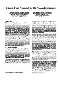
As mentioned earlier we see MDE as an integration of languages, models, tools, methods, processes and frameworks that allow us to specify and analyze systems in a consistent manner, starting from the requirement specification and down to the physical implementation. In order to provide a systematic approach to system design, a methodology that guides the designer and provides the necessary tool support has to be defined. Our design methodology (Figure 1) starts with the functional specification of the application, and when the necessary level of detail is reached, we map the specification onto the target platform. We make use of domain information to narrow the gap between the functional specification and the platform, and to provide support for reuse of components. Although in the spirit of MDA, where the application specification is separated from the platform implementation into two different models, PIM and PSM, respectively, our approach allows targeting the application onto target architectural configurations not known at design time. Consequently, the methodology gives us the possibility to configure a target (hardware) platform while performing the application specification, in contrast with traditional approaches where the application has to be mapped onto a fixed given platform. Following we briefly present the phases of the design methodology.
3.1
Functional Specification of the Application
In the area of embedded systems there are mainly two categories of approaches promoting concepts and artifacts that can be viewed as common modeling languages. First category is based on the use of the object-oriented 4
Requirements Specification
Domain Knowledge (Operations List)
IPv6 Router
Comm. Protocols
Functional Specification
Hardware Architecture TACO Processor
(UML-DFD integration)
Domain Independent Platform Independent
Domain Information
Domain Dependent Platform Independent
Platform Configuration & Code generation
Domain Dependent Platform Dependent
Figure 1: Design Methodology for Protocol Processing Applications paradigm, which has been the starting point of the Unified Modeling Language. The second one is based on the data flow paradigm that promoted the data flow diagrams (DFDs) as its main modeling language. Both models offer important views of the system at hand, but each of them focuses on certain aspects of the system under consideration. Sometimes it is useful to be able to transform one model into another, allowing the designer to focus on a particular view of the system. We extract the functional requirements of the application into an initial specification and we specify it in a domain independent and platform independent manner. At this point no details about the target domain and platform are being taken into consideration. During the functional specification we integrate and combine the object-oriented and data flow views for the analysis and design of embedded systems. The approach consists of specifying the system following a functional decomposition and representing it using the benefits of both object-oriented and DFD views. The argumentation for the necessity of integrating both views was given in [6]. The design-flow (Figure 2) is composed of a number of steps that represent different views of the system. a. Extract the application requirements b. Extract functionality of the system into a Use Case Diagram c. Specify the textual description for each use case 5
a. Extract Application Requirements
b. Create Use Case Diagram
Use Case Diagram
c. Specify Use Cases d. Create Initial Object Diagram
Use Case Description
Initial Object Diagram
refinement
e. Create Data Flow Diagram
Data Flow Diagram g. Create Activity Diagrams
f. Build Data Dictionary
Data Dictionary Activity Diagrams
i. Create DFD-like Object Diagram
h. Create Class Diagram
Object Diagram
Class Diagram
Figure 2: The main steps of the UML-DFD functional specification d. From the Use Case Diagram we obtain the Initial Object Diagram of the system. Based on the use cases textual description, the Initial Object Diagram is refactored by grouping, splitting or discarding of the objects e. Transform the Initial Object Diagram into a Data Flow Diagram f. While refining the communication (DataFlows) inside the DFD, we build the Data Dictionary of the system g. Specify the internal behavior of the DataTransformations using Activity Diagrams h. Transform the Data Flow Diagram into a Class Diagram i. Transform the Data Flow Diagram into a DFD-like Object Diagram 6
Between steps, the designer changes several times the view of the system and consequently, the modeling paradigm. Between the views we have implemented model transformations that allow us to go from one step to another in an automated way. We show later in this paper how we have implemented and used these transformations. A more detailed view of the design flow and how we automated these transformations between different views of the system can be found in [24]. In the current document we only intend to analyze the methods used in the approach, and based on this analysis, to identify the general characteristics of a Model Driven Engineering process.
3.2
Using Domain Information
We combine the functional specification of the application with the domainbased knowledge to provide component reuse and fast identification of required computational resources. During this phase we transform the functional specification of the application into a domain dependent but still, platform independent specification. Analyzing and modeling the domain knowledge, a set of generic reusable components can be extracted by identifying general abstractions and similarities of a set of applications. For the given range of applications, i.e. protocol processing, we claim that there is a common set of basic domain operations that have to be supported/implemented by a system. We use domain operations as a bridge between the functional specification and the target platform. Basically, on one side we express the functional specification of the application using domain operations related to a given application domain, on the other side we identify how the domain operations map onto the platform resources. The end result of the process is a functional specification of the application expressed with domain operations that are directly mappable onto the target resources.
3.3
Platform Implementation
One of our aims is to keep our design methodology applicable to a wider range of embedded systems. Once the functional specification of the application has been performed, different target architectures can be chosen for implementation. Each domain operation is implemented by certain resources of the given target platform(s), thus allowing us to identify the required resources needed to implement the application. For a given target platform we identify what domain operations a target platform is able to implement, and then we map the domain-dependent functional specification onto that platform. The approach can be used to implement the application both onto 7
fixed-configuration platforms, and as well as onto configurable ones. Keeping the application specification independent of the target platform allows designers to take implementation specific decisions later in the design flow, thus addressing an important issue of the hardware/software co-design domain. In addition, one can implement the same application specification on various target platforms based on performance needs and physical constraints. To verify the validity of the methodology, we have applied the approach to specify and design an IPv6 Router, using the Java programming language [1], and into hardware using our TACO protocol processing platform [12] as target implementation platforms. We have used this design methodology for designing protocol processing applications implemented on our TACO processor. TACO provides an integrated framework for fast configuration, simulation, evaluation and implementation of different TACO processor configurations. The TACO processors are simulated using the SystemC language [20], their physical characteristics are estimated using a Matlab model and a VHDL model is used for the hardware synthesis.
4
Layers 0 and 1 — Models, Tools and Model Evolution
A model-based development method consists of several supporting paradigms. When discussing a method in concrete terms, the surrounding environment must be taken into consideration. In modeling, that environment consists of the interoperable tools and the facilities that they provide, available languages and rules of how, when and why to manipulate models. Model manipulation, aside from that provided by the editing tools themselves, is given as scripts in our framework. They are used to provide three different kinds of model manipulation, that of querying, model-to-model manipulation and artifact generation. Similar functionality can no doubt be found or be expected by other manipulation systems such as QVT [13].
4.1
Models and Modeling Languages
From our point of view, the two main advantages of using models versus source code to describe our software is that we can store all the relevant information needed in a software project in the model and that all the information in a model is stored in a standardized and uniform way that can be processed and transformed easily. The idea that we can use the same modeling language to describe the analysis, design and implementation of a system has been always one of the 8
most repeated features of UML. Actually, UML lacks in certain areas such as describing non-functional requirements and real-time domains, but successive extensions to the standard could alleviate these problems. However, there is a clear danger in believing in the silver bullet. A more realistic scenario is that we have to be able to experiment with new methodologies and languages, without giving up on what we already possess. In light of this stepwise incorporation of novel technologies, the need for new metamodels comes forward. There is a strong need to explore new modeling languages and concepts, without trying to incorporate everything into UML. Metamodeling is the field of describing, evolving, maintaining and extending metamodels providing mathematical rigor where possible in the form of (possibly heuristic) verification, and practical statistics of the models in question. A sound practice is to try to map between our various metamodels and the UML, which has become the de facto standard. Transparent mapping of models to other domains provides us with the required integrity and seamless interoperability. Many developers see UML as a graphical representation of the source code in the system. This view prevents us to include other artifacts such as a spreadsheet or a Mathematica document in our model, even when the contents of those documents can be relevant to our software. We prefer to consider a modeling language as a taxonomy of the most important concepts that can occur in an abstract description of a design. Another important feature of modeling languages such as UML is that while the models may be represented diagrammatically using icons, they are stored using an object graph similar to the abstract syntax tree of a programming language. In the case of UML, the abstract syntax is defined by the UML metamodel. The metamodel representation is akin to a directed graph. Each node of the graph represents a metamodel element and each arc a relationship between two metamodel elements. Some arcs represent compositions, i.e. whole-part relationships. In the case of UML, if we consider only the composition arcs, the resulting graph is also a tree. The advantage of storing a software project as an object graph is that we can traverse the project, collect, add and remove information from it in a way that is independent of the target programming language. This task is simplified by languages such as OCL that have specific constructs to navigate models. Using OCL or a similar query language is not restricted to UML, but to the language of metamodels, which in MDA is the Meta Object Facility. 9
4.2
MDE Tools
CASE tools have a huge role in the MDA and MDE initiatives due to the graphic nature of models, the way models are stored, and the fact that many of the benefits of these approaches only arise through automation. Our vision is that a typical MDE project will be carried out using not one but several development tools. There are many different variables in a project such as translation to the target platform, knowledge of the application domain, analysis, estimation (e.g. the TACO framework), and we cannot expect that one single tool will be able to cover the whole development process for all the necessary variables. Thereby ease of communication between these tools is of essence. A true common file format for model interchange would allow a market for new specific tools for model transformation and code generators. Some of these tools could be specialized in application domains such as real-time systems. In many cases the selection of tools such as a model editor would be just a matter of personal preferences as it is now with text editors. This scenario is described in [23] and it requires two components: a standard interchange file format, and tools that comply with it. Unfortunately, in the case of UML, this is still not a reality, as different tools implement the XMI standard differently. Furthermore, by providing multiple ways to serialize the same model parts, the standard has only made it more complex for multiple implementations to co-exist. Also, XMI is designed for the abstract model and does not contain any information about graphical parts. The XMI-DI standard for diagrammatic interchange [19] is not yet so widespread, but we hope that this situation will change in a near future. We will assume tool support in the form of diagram editors, transformation frameworks and similar frameworks as an issue of quality of implementation, and concentrate on the facilities that they must provide.
4.3
Versioning
Model versioning encompasses the idea of continuous model evolution. Models change, either by small changes made by the designer, or by bigger changes by automated transformation tools. Nevertheless, the need to distinguish between different versions of a model is required. Here we can draw experience from our collective know-how of how ordinary file-based versioning is accomplished, its benefits and problems, and apply that to the world of models. The base operation of a model versioning system is to be able to retain old revisions of the models. A part of realizing this is the ability to calculate the difference between two arbitrary models [?]. A development environment can 10
use the same facility to provide transactional support for the changes that the modeler does, i.e., supporting undo/redo mechanisms. At the moment, there is no practical standard for exchanging differences; the XMI.Difference element, as defined in the XMI standard, is too coarse-grained and there is to our knowledge no tool which supports it. A configuration management and versioning system is not a mere lackluster scheme where only changes are recorded. In the long run, we hope that intent is reflected more clearly in the changes to a model. This could be realized with connections to a project management-specific or process model, where tasks, errors, assumptions and estimations are recorded and managed. These systems together are a part of the development process; they guide the developers and enforce the project’s process upon their development.
5
Layer 2 — MDE Scripts
A MDE script is a small application that processes a software model in order to extract information from it, transform it or create a derived artifact such as source code. At the time of writing this text, there is an ongoing effort in the OMG to standardize on a language suitable for querying and transforming models based on MOF, such as the UML. In our case, we have decided to use the scripting language provided by the SMW tool [3]. SMW is a toolset based on the Python programming language, an object-oriented interpreted scripting language. Python is easy to learn and features a simple, yet elegant syntax. SMW is organized in four main layers: the SMW kernel, a generic editor layer, the language specific editors and the method specific scripts. The SMW kernel is in charge of representing models in memory. Each element in a modeling language is represented as a Python class and each element in a model is represented as an instance of the corresponding class. The kernel ensures that the models are well-formed. It also provides support for XMI, the standard file interchange format between UML tools, OCL-like idioms for model query and navigation, and user-defined modeling languages. A SMW modeling language is defined in a metamodel file. In the case of the UML language, it is generated automatically from the official OMG files. We have used the basic facilities provided by the kernel to create a generic diagram editor. The generic editor provides functionality such as printing or a clipboard that is implemented independently of the actual modeling language used in a given model. The generic editor can be customized into a language-specific editor such as the UML editor, an extension to standard UML and even other modeling languages, such as the SMW extension to 11
model data flow diagrams (the SA/RT profile [10]) that we use in our design flow. The actual method engineering support is provided by customized scripts. We have identified three script types that are required to be supported by an MDE process. They operate over model elements as well as over entire models. 1. Queries are applied on a model expressed in one language and returns a set of elements of the same model expressed in the same language. 2. Model Transformations are applied on a model expressed in a given language and either modifies the model in place, or creates a model, possibly expressed in a different language. The upcoming QVT standard from OMG addresses this problem. Model transformations conceive a plethora of new interesting questions and topics, such as transformation taxonomy, correctness-preserving transformations, consistency checking and/or verification. 3. Code Generation, although a form of transformation, is sufficiently different from a model-to-model transformation to merit its own classification. The goal is to produce suitable input to a second-stage compilation or analysis tool. The target language is not a metamodel. The main difference between queries and transformations is that the queries are free of side-effects, meaning that when applied on a model they do not change the model in any way.
5.1
Queries: Constraints, Metrics and Guidelines
The simplest MDE script is a query. A query gathers information from a model but it does not update it. OCL [17] is probably the most standard and known language for UML queries. Usually a query gathers information from a model in the form of collection of elements. In addition, we consider that there are yet three other specific uses of queries: defining software metrics, model constraints and design guidelines. The main purpose of a query is to extract, from a model, parts of or all model elements corresponding with the query condition. An example of such a query is obtaining a list of all objects that are instances of a given class. In order to perform the query we use the method getAllParts that returns all the elements transitively owned by the object. If we invoke this method with the root element of the model we obtain a collection that contains all other elements in the model. 12
1 2 3
instances=model.getAllParts().select(lambda c: c.oclIsKindOf(Instance) and c.classifier=someClass).name
A query can represent a design guideline when it is used to verify that all elements in the model have been created and are consistent with the development method. In our example we have followed the design flow with a functional decomposition of the system where each class in the specification should still correspond to the initial use cases. In the following example, the lines 1–3 collect all stereotype names (ucStereotypes) present in the use case diagram of the system. Consequently, lines 4–8 create a collection of classes (unRelated) whose stereotype names are not present in the use case diagram. 1 2 3 4 5 6 7 8
ucStereotypes=model.ownedElement.select(lambda uc: uc.oclIsKindOf(UseCase)).stereotype.select(lambda st: st.oclIsKindOf(Stereotype)).name unRelated = model.ownedElement.select(lambda cl: cl.oclIsKindOf(Class) and cl.stereotype.select(lambda st: st.oclIsKindOf(Stereotype) and st.name not in ucStereotypes))
Of course, more complexity can be added to the previous verification in order to gather more details on the relation between each class and different use cases. One should note that one class can belong to several use cases or the reverse, one use case can be contained by one class, even though this situation occurs less frequently. Finally, a query can be used to ensure that a design can be implemented in a given target platform. In our example, we check that the design is still implementable onto the target platform after a refactoring has been performed. In practice, this means that all the class methods should still have at least one implementation solution provided by the target platform. 1 2 3 4 5 6
implementable = model.getAllParts().forAll(lambda actDiag: actDiag.oclIsKindOf(ActivityGraph) and actDiag.ownedElement.forAll(lambda tran: tran.oclIsKindOf(Transition) and tran.source.oclIsKindOf(ActivityState) and belongsTo(tran.source.name, platformOperations)))
The example interrogates all activity diagrams inside a model, and checks that each state is expressed using a platform operation provided in the platformOperations list (line 6). 13
5.1.1
Software Metrics
Software metrics are an application of model queries. We can extract design and implementation metrics from a software model by applying an aggregation operator over a set of queries of a model. Let us take as an example the total number of classes in a model. This simple metric may give us a rough estimation of the effort needed to implement the model. Here, we begin by selecting all the classes in the model, and use the size operator to count the number of classes. 1 2
NOC=model.getAllParts().select(lambda c: c.oclIsKindOf(Class)).size()
Another interesting metric is the number of operations per class. The following query creates a collection that contains an integer with the number of operations for each class. 1 2 3 4
MpC = model.getAllParts().select( lambda c: c.oclIsKindOf(Class)).collect( lambda c: c.feature.select(lambda f: f.oclIsKindOf(Operation)).size())
In this query we first find all classes in the model. Then we use the collect operator to calculate the number of operations in each class. Once we have created the final collection we can calculate the average and maximum number of methods per class in the model. We can also use the stats Python module to print a histogram of the metric. AverageNumberOfMethods = MpC.sum() / MpC.size() MaximumMethodsPerClass = max(MpC) import stats print stats.histogram(MpC)
The histogram may reveal that some classes are too large. Probably these classes represent several abstractions and can be refactored into two or more simpler classes. The following query returns the names of the classes in the model that have the most number of operations. 1 2 3
model.getAllParts().select(lambda c: c.oclIsKindOf(Class) and c.feature.select(lambda f: f.oclIsKindOf(Operation)).size() >= max(MpC) * 0.9).name
5.1.2
Target Platform Constraints
Another important type of query is to check if a model fulfills a given constraint of the target platform. These constraints can be dictated either by 14
the implementation programming language, the target operating system or, in our case, by the hardware platform. For instance, in our design flow one would like to avoid using the multiple implementation inheritance (especially if we are talking about mapping the specification into hardware). For this we have to identify (see the script below) the presence of the classes that use multiple inheritance in our design. 1 2 3 4 5
model.getAllParts().select( lambda c: c.oclIsKindOf(Class) and not c.isAbstract and c.generalization.size()>1 ).name
In this script we select from all classes in the model (lines 1–2) those representing a concrete class to be implemented (l. 3) and have more than one superclass (l. 4). Then we collect the names of the selected classes (l. 5) 5.1.3
Design Guidelines
Another application for queries is to check whether or not a model follows some design guidelines. Some tools such as Together Control Center from TogetherSoft provide an auditing feature that reveals common design and programming mistakes. ArgoUML [22] provides a similar mechanism with its critics system. Argo critics give advice in real-time, while the designer manipulates the model diagrams. As an example, the following method returns true if a class has an invariant. The invariant may be defined in the given class (line 2) or in any of its superclasses (l. 4). 1 2 3 4 5 6
def hasInvariant(c): if c.constraint.exists(lambda e: e.name=="invariant"): return true else: return c.generalization.exists(lambda g: hasInvariant(g.parent))
Given the function hasInvariant the next query returns the name of the classes that do not have an invariant defined: 1 2
model.getAllParts().select(lambda c: c.oclIsKindOf(Class) and not hasInvariant(c)).name
5.2
Model Transformations
Model transformations can be categorized based on the scope of their effect on a given model. They can be applied to modify internal parts (elements) of 15
a model (update transformation) or to create a new model expressed in the same language or in a different language (mapping transformation). Usually, a model transformation requires a script with a higher complexity than a query. In fact, a transformation is composed of one or many queries that select from the model the required elements, satisfying a given condition or being in a certain relation, and then one or many create, edit or delete operations performed over the target model elements. A mapping transformation translates each element from a source model into zero, one or more elements of a target model. The source and target models may be described in the same or in different modeling languages. In a mapping transformation, the original model is not altered. There are many articles in the literature describing mapping transformations, including a survey in [9]. Recently, Akehurst and Kent proposed to use relations to define these mappings [2]. Also, the OMG has a request for proposals for a MOF-based transformation language. At the time of writing this text, there are eight different submissions. We consider that mapping transformations are more suited to describe transformations where a whole model is translated from one language to another. An example of a mapping transformation is our work on converting a DFD element into a UML Class. In contrast, an update transformation modifies a model in place: it adds, deletes and updates elements in one model. The source and target models are the same and the effects of the transformation are visible while performing the transformation. There can be two kinds of update transformations: to modify an already existing element or to create a new element of the same type followed by the deletion of the initial element. The update transformation is obviously a more efficient approach when only a small subset of the source model will be changed by the transformation. A trivial example is the addition of a new UML Class to a Package. This involves the creation of a new model element, and modifying the bidirectional association between the Class and the Package. 5.2.1
Model Refinement and Refactoring
Model refinement and refactoring is a new area of research. We have experience in source code refactorings and refinements, but in modeling it is quite a new concept—probably because a de facto standard for expressing transformations has not been developed yet. Different definitions for refactoring have been given in the literature. Fowler says that ”The process of changing a software system in such a way that it does not alter the external behavior of the code, yet improves its internal structure” [7], while Beck considers that a refactoring is ”a change to the system that leaves its behavior 16
Person -name : String -age : Integer
Person +name : String +age : Integer
=⇒
getName() : String setName(newValue : String) getAge() : Integer setAge(newValue : Integer)
Figure 3: Attribute Encapsulation
unchanged, but enhances some non-functional quality—simplicity, flexibility, understandability, . . . ” [4]. We consider that model refactoring is a more complex case of model transformation where the update transformation is applied on the entire model. We define a refactoring as a behavior-preserving transformation in a model with the objective to improve the design described in it. In our work, we have used a rule-based approach [21] provided by the SMW tool. It allows us to mix OCL-style queries and preconditions with imperative statements that modify the model. Parts of a script for a standard example, encapsulating an attribute of a class, is shown below. The script modifies a public attribute to become private, and adds a suitable getX() method instead. The effects of the refactoring is presented in Figure 3. 1 2 3 4 5 6 7 8 9 10 11 12 13 14 15 16 17 18
transformation EncapsulateAttribute: rule AddGetter(a: Attribute): when: a.visibility==VisibilityKind.vk_public and not a.owner.feature.select(lambda f: f.name=="get"+string.capitalize(a.name)) do: a.owner.feature.insert( Operation( name="get"+string.capitalize(a.name), visibility=VisibilityKind.vk_public, parameter=[ Parameter(name="result",type=a.type, kind=ParameterDirectionKind.pdk_return) ], specification="return "+a.name) ) rule Privatize(a: Attribute): when: a.visibility==VisibilityKind.vk_public and not AddGetter.guard([a]) and not AddSetter.guard([a]) do: a.visibility=VisibilityKind.vk_private
5.2.2
Model Mapping
Model mapping is the process of transforming a source model into a target model that either belongs to the same formalism/language or to a new one. The transformation is done without modifying the initial model. An example of model mapping between similar formalisms is transforming a UML 17
Class Diagrams into a new UML Class Diagram. In contrast, transforming a UML Class Diagram into a Data Flow Diagram is an example of mapping between different formalisms. Usually, a model mapping process involves a combination of MDE scripts (queries and transformations) on different model elements. The basic pattern is that first we “extract” those elements of the model that meet a given condition (query) and on the obtained set we apply a series of transformations. In the functional specification of the application presented in Section 2, we apply a number of model mappings. One example is the transformation (step d. of Figure 2) of a UML Use Case Diagram (Figure 4 - top) into a UML Object Diagram (Figure 4 - bottom), remaining within the UML formalism. Basically, the algorithm consists of transforming each actor element in the first model into an actor element in the second model, 1 2 3
ucActors=umlModel1.ownedElement.select(lambda x: x.oclIsKindOf(Actor)) for act in ucActors: p=umlModel2.ownedElement.insert(UML14.Actor(name=act.name))
then based on the approach described in [5] each use case is split into three different objects (interface, control, data) and the corresponding classes are created: 4 5 6 7 8 9 10 11
useCases=umlModel1.ownedElement.select(lambda x: x.oclIsKindOf(UseCase)) for el in useCases: classInterface=umlModel2.ownedElement.insert(UML14.Class(name=el.name, stereotype.append(Stereotype(name="interface")))) classControl=umlModel2.ownedElement.insert(UML14.Class(name=el.name, stereotype.append(Stereotype(name="control")))) classData=umlModel2.ownedElement.insert(UML14.Class(name=el.name, stereotype.append(Stereotype(name="data"))))
In this transformation we use an approach where interface objects are the only objects communicating with the external environment, while the communication among interface and data objects is always done through control objects. Thus, we draw by default associations between interface and control objects, and also between control and data objects. 12 13
assoc1=umlModel2.addAssociation(classInterface, classControl) assoc2=umlModel2.addAssociation(classControl, classData)
Finally, for each association actor-use case in the initial model, an association is drawn between the corresponding actor and the interface object corresponding to the initial use case. 14 15 16 17 18 19 20 21
ucAssocs=ucd.ownedElement.select(lambda x: x.oclIsKindOf(UML14.Association)) ucAssocs.select(lambda assoc: ucd.ownedElement.select(lambda el1: (el1.oclIsKindOf(Actor) or el1.oclIsKindOf(UseCase)) and assoc.connection[0] in el1.association and ucd.ownedElement.select(lambda el2: (el2.oclIsKindOf(Actor) or el2.oclIsKindOf(UseCase)) and assoc.connection[1] in el2.association and model.addAssociation(el1,el2,assoc.name))))
18
IPv6 router
{3.} Treat Request
{1.} Forward Datagram
{4.} Inform Topology
{2.} Send Error
node
{5.} Update R'ting Table
router
{6.} Create Request
node forwarding datagram
node error datagram
router
router
request datagram
response datagram
router response datagram
router request datagram
{1.i}
{2.i}
{3.i}
{4.i}
{5.i}
{6.i}
{1.c}
{2.c}
{3.c}
{4.c}
{5.c}
{6.c}
{1.d}
{2.d}
{3.d}
{4.d}
{5.d}
{6.d}
Figure 4: Transformation of a Use Case Diagram into an Object Diagram
One should note that although the OCL is specified to be a declarative language, the Python lambda functions allow us to use it also as an imperative language. This enables us to mix queries with model manipulations, making the scripts shorter and more effective. We mention that the object diagram obtained in Figure 4-bottom does not represent the exact output of the transformation. As mentioned in the step d. of our functional specification design flow, a refactoring process is performed on the object diagram resulting from the transformation. The refactoring is done manually (and based on designer’s experience) and consists of giving a direction to the associations between objects and also deciding which objects are grouped and/or discarded. For instance in Figure 4-bottom, data objects {2.d}, {3.d}, {4.d}, {5.d} and {6.d} represent the same functionality of the 19
system, so they can be grouped into one single object {5.d}, and the others are discarded. A second example of mapping between two different models, this time also changing the formalism/language, is the transformation that supports the creation of an object diagram in the UML model, starting from a dataflow diagram in the DFD model (Figure 2, step i.). The transformation is applied onto a data-flow diagram presented in Figure 5-top. The four modeling concepts that are present in a DFD are: data flows (movement of data in the system), data stores (repositories for data that is not moving), processes (transformation of incoming data flows into outgoing data flows), and external entities (sources or destinations outside the specified system boundary). The end product of the transformation is the diagram in Figure 5bottom. The diagram proved to be suited for prototyping purposes and functional testing of the specification. Additionally, it is already a good candidate for being mapped onto a hardware-based platform, because its granularity is at a relatively low level of detail, similar with the one provided by the TACO processor. The model transformation starts by gathering model information using a number of basic queries. 1 2 3 4 5 6 7 8
dataFlows=dfdModel.ownedElement.select(lambda x: x.oclIsKindOf(DataFlow) and not x.oclIsKindOf(DataStore)) externalEntities=topDfd.ownedElement.select(lambda x: x.oclIsKindOf(ExternalEntity)) dataStores=topDfd.ownedElement.select(lambda x: x.oclIsKindOf(DataStore)) dataTransformations=topDfd.ownedElement.select(lambda x: x.oclIsKindOf(DataTransformation))
Next we transform each Data Transformation and each DataStore in the DFD model into a class diagram in the UML model. 9 10 11 12
dfdModel.ownedElement.select(lambda ts: (ts.oclIsKindOf(DataTransformation) or ts.oclIsKindOf(DataStore)) and classDiag.addClass(name=ts.name))
Then we add associations among classes. An association among two classes is obtained from the data flow among the two Data Transformations or Data Stores corresponding to those classes. 13 14 15 16 17 18 19 20 21
dfdModel.ownedElement.select(lambda f: f.oclIsKindOf(DataFlow) and dfdModel.ownedElement.select(lambda src: src.oclIsKindOf(DataTransformation) and f.connection[0] in src.association and dfdModel.ownedElement.select(lambda dst: dst.oclIsKindOf(DataTransformation) and f.connection[1] in dst.association and addAssoc(src,dst,"send"+string.split(f.name,’+’)[0]))))
20
Foward Datagram
Routing Datagram
{1a.i} ReceiveFwd
{3.i+5.i} Receive Routing RequestDatagram+ RecvInterface
FowardDatagram+ RecvInterface
FowardDatagram+ RecvInterface+ ErrorType
{1a.c} Validate
ResponseDatagram+ RecvInterface
RequestDatagram+ RecvInterface+ ErrorType {3.c} Request
{2.c} ICMP
{5.c} Response
ResponseDatagram+ RecvInterface+ ErrorType
FowardDatagram+ RecvInterface
RTEs
Trigger Response {1.d} dataStore
{5.d} Routing Table
RTEs
RTE#
FowardDatagram+ RecvInterface
ErrorDatagram+ RecvInterface {4.c} Create Response
ForwarddDatagram+ RecvInterface+ ErrorType
{1b.c} Forward
{6.c} Create Request
RTEs
ResponseDatagram+ Interface(s) FowardDatagram+ FwdInterface RequestDatagram+ Interface(s) {1b.i} SendForward
{2.i} SendICMP
{4.i+6.i} SendRouting
Foward Datagram
Error Datagram
Routing Datagram
{1a.i} receiveForward «methods» setFwdDatagram()
{3.i+5.i} receiveRouting «methods» setRequest( ) setResponse( )
sendFwdDatagram()
check()
check()
{1a.c} validate
{3.c} Request
{5.c} Response
«methods»
«methods»
«methods»
sendRequestDatagram()
sendResponseDatagram()
sendFwdDatagram( ) sendFwdError()
sendFwdError() store()
writeFwdDatagram() sendRoutError()
{1.d} dataStore
{2.c} ICMP
«methods»
«methods»
readFwdDatagram(,) writeFwdDatagram(,)
{5.d} routingTable
setTrigger()
«methods»
sendFwdError() sendRoutError()
writeRTE() readRTE()
readRTE()
readFwdDatagram()
{1b.c} Forward
readRTE()
sendRoutError()
«methods»
{6.c} CreateRequest
«methods»
run( ) sendErrorDatagram() send()
run() setTrigger()
«methods» run()
sendResponseDatagram()
{1b.i} sendForward
{2.i} sendICMP
«methods»
«methods»
sendFwdDatagram()
writeRTE()
{4.c} CreateResponse
sendRequestDatagram()
{4.i+6.i} sendRouting «methods»
sendErrorDatagram()
sendResponseDatagram() sendRequestDatagram()
Figure 5: Transformation of a Data-flow Diagram into an Object Diagram
21
The definition of the function addAssoc() is given below. Its functionality is to add an association with a given name corresponding to a source and a destination element in the source model. To do this, the function queries the target model to select corresponding elements and adds the new association to the target model. 1 2 3 4 5 6 7 8 9
def addAssoc(source,destination,theName): umlModel.ownedElement.select(lambda src: src.oclIsKindOf(Class) and src.name==source.name and umlModel.ownedElement.select(lambda dest: dest.oclIsKindOf(Class) and dest.name==destination.name and classDiag.addAssociation(src, dest, name=theName+"()"))) return 1
A third example, that we only mention for the sake of example without getting into details, is mapping of the functional specification of the application onto a target implementation platform. As mentioned in the very beginning of this paper, we have applied the approach introduced in section 3 to the specification and design of an IPv6 router. There, the target implementation platform was represented by our configurable TACO protocol processor [25]. The components of the processor (functional units and buses) are implemented and simulated using the SystemC language, which is an extension of C++ used for hardware specification. We used the SystemC class diagram of the TACO components [25] as a model in the SMW tool. By using a similar approach as in the transformations presented above, this allowed us to implement transformations that map the functional specification of the application (i.e. the IPv6 Router) onto the TACO platform. In addition, during the mapping process we were able to create configurations of the processor in a automated manner by selecting those resources needed by the application.
5.3
Artifact Generation: Specification, Code and Documentation Generation
Code generation is the translation of a model into a new textual artifact. This artifact can be a program in a language such as Java or C++, documentation in PDF or in HTML format, or a specification for another tool, such as proof obligations for a theorem prover, a specification for a model checker or hints for a test driver. There are three properties that we can consider in a code generation tool: compliance with the syntax of the target language, compliance with the semantics of the modeling language, and traceability and reverse engineering. The two first points are very important for the proper 22
functioning of an artifact generator, while the final one empowers us to follow how elements have mapped to the artifact, and can aid us in mapping parts of the artifact back to the modeling realm. The issue of syntactic compliance entails how we can ensure that all artifacts generated by the translation tool are syntactically correct. While implementation might not be trivial, verification usually is since artifact languages tend to have e.g. BNF grammars that completely automate the process of determining syntactic correctness. As such we do not believe syntactical issues to be much of a burden. Language correctness questions how we can ensure that the transformation is semantically equivalent in both the modeling language as well as the target artifact language. Even though theory might doom this question to be undecidable, in practice we have a lot of experience in compiler technology, and there is little reason to believe that artifact generation from models is distinctively different from compilation. Indeed there are many similarities, and we can be reassured in the viability of this task by taking a glance at the accomplishments of compiler technology. Compilers are gradually getting better, even for complex languages, and there is no reason to believe that similarly good products could not be created for the modeling industry as well in the long run. Traceability implies knowledge of the origin of the parts of the artifact. Especially for debugging, understanding which elements provided a certain effect to the generated artifact is an understandable gain. This can be accomplished by annotating the actual artifact with suitable fields for comments (Figure 4), or by generating a stream of trace messages. In both cases, a tool could combine artifact information with trace information to pinpoint which parts of the model that participated in a specific part of an artifact. Reverse engineering tries to map the generated artifact back to a model, possibly without any origin model with which to compare. When compared with traceability, even though it looks at the map between the model and the artifact from a slightly different point of view, the problem is still similar.
6
Conclusions
In this article we have presented our understanding of the Model Driven Architecture and extended it with ideas proposed in [11]. The MDA initiative describes one very significant part of model evolution, that of platform independent and platform description models conceiving a platform specific model. Although MDA is a valid systematic way to describe structural properties of software, the dynamics of the software process are missing. To aid 23
in this, process methodologies must be defined and adhered to, not only on the corporate plane but on the actual modeling and development plane. In our example of a hardware/software co-design problem, there is no platform description model, as it is developed with the rest of the program. This kind of synergy between the underlying platform and the software running on it is missing from MDA. We hope that MDE encompasses a broader field by taking an evolving platform into account. Applying engineering concepts in MDA is still in its infancy. However, the need is clearly evident, and related work in this field is present. The Generative Model Transformer (GMT) [8] is an open source initiative that wants to fulfill the promise of MDA, and encourage exploration and research related to MDA. GMT sounds very promising, as a joint tool effort could be the missing link between everyday modeling and the software development community. Involving project policy in modeling as a primary aspect of the available languages and tools empowers software engineering to be a discipline, rather than an ever-changing ad hoc mesh of ill-mannered procedures. It requires standards for all activities in modeling, ranging from standards to encode, decode and transform models, following and modifying process methodologies, communication between the tools, or graphical communication between the tools and the user, to standard libraries of any aforementioned activities. Furthermore, we have shown what we consider is the best benefit we can achieve from the MDE: we were able to script and automate our development process in the context of a case study of an IPv6 router using our TACO protocol processing architecture. The idea does not come without dangers; most problems can in fact be said to still exist even in the modeling world. Examples abound, mostly regarding the culture of the development group: measuring e.g. model evolution by the amount of elements or transformation scripts is as good or bad a metric as KLOC/month. As mentioned earlier, standard libraries for modeling will pop up, but they might fall to similar problems as our current plethora of different, mutually incompatible library versions. Even worse, unmaintained transformation scripts, models, processes or libraries will succumb to “bit rot” and become as obsolete and difficult to maintain, review and update as any other legacy program. There are still many reasons to encourage the use of models and the concept of everything is a model . Models are described at the right level of abstraction and precision. Source code is too concrete, natural language is too ambiguous. New languages can easily be explored because of the common structure inherent in all models and metamodels, as given by a common meta-metamodel. This implies that it is simpler to construct a tool to extract semantic information about a design from a model of any language. 24
Although our case study represents a specific application, this is exactly where we think that an MDE approach is more valuable. The more specific our application domain, the more difficult it is to find trained developers that are familiar with the application domain and therefore, the higher profit can be obtained from using a well-defined process and advanced tools to guide and help the developers.
Acknowledgments Dragos Truscan gratefully acknowledges the financial support for this work from the HPY research foundation.
References [1] http://www.abo.fi/~dragos.truscan/ipv6index.html. [2] David Akehurst and Stuart Kent. A Relational Approach to Defining Transformations in a Metamodel. In Proc. UML 2002 - The Unified Modeling Language. Model Engineering, Languages, Concepts, and Tools. 5th International Conference, Dresden, Germany, volume 2460 of LNCS. Springer-Verlag, 2002. [3] Ralph Back, Dag Bj¨orklund, Johan Lilius, Luka Milovanov, and Ivan Porres. A Workbench to Experiment with new Model Driven Engineering Applications. In UML 2003, volume 2863 of LNCS. Springer-Verlag. [4] Kent Beck. Extreme Programming Explained. Addison-Wesley, 1999. [5] Joao M Fernandes, Ricardo J. Machado, and Henrique D. Santos. Modelling Industrial Embedded Systems with UML. In Proceedings of CODES 2000, San Diego, CA USA, 2000. [6] Jo˜ao Miguel Fernandes. Functional and Object-Oriented Modeling of Embedded Software. Technical Report 512, Turku Centre for Computer Science (TUCS), Turku, Finland, 2003. [7] Martin Fowler et al. Refactoring: Improving the Design of Existing Code. Addison-Wesley, 1999. [8] Generative Model Transformer. http://www.eclipse.org/gmt/. 25
[9] A. Gerber, M. Lawley, K. Raymond, J. Steel, and A. Wood. Transformation: The missing link of MDA. In A. Corradini, H. Ehrig, H.-J. Kreowski, and G. Rozenberg, editors, Proc. Graph Transformation First International Conference, ICGT 2002, Barcelona, Spain, volume 2505 of LNCS. Springer-Verlag, 2002. [10] J. Isaksson, D. Truscan, and J. Lilius. A MOF-based Metamodel for SA/RT. Technical Report 555, Turku Centre for Computer Science (TUCS), Turku, Finland, 2003. [11] Stuart Kent. Model Driven Engineering. In IFM 2002, volume 2335 of LNCS. Springer-Verlag, 2002. [12] J. Lilius and D. Truscan. UML-driven TTA-based Protocol Processor Design. In Forum on specification and Design Languages (FDL ’02), September 2002. [13] OMG. MOF 2.0 Query / Views / Transformations RFP. OMG document ad/02-04-10. Available at www.omg.org. [14] OMG. OMG Meta-Object Facility (MOF). OMG Document formal/0111-02. Available at www.omg.org. [15] OMG. Omg XML metadata interchange (XMI) specification. OMG Document formal/00-11-02. Available at www.omg.org. [16] OMG. Softrware Process Engineering Metamodel Specification (SPEM). OMG Document formal/02-11-14. Available at www.omg.org. [17] OMG. Object Constraint Language Specification, version 1.1, September 1997. Available at http://www.omg.org/. [18] OMG. OMG Model Driven Architecture, July 2001. ormsc/2001-07-01, available at http://www.omg.org/.
Document
[19] OMG. UML 2.0 Diagram Interchange draft adopted specification, July 2003. OMG Document ptc/03-07-03. Available at http://www.omg. org/. [20] Open SystemC Initiative. http: // www. systemc. org . [21] Ivan Porres. Model Refactorings as Rule-Based Update Transformations. In UML 2003, volume 2863 of LNCS. Springer-Verlag. 26
[22] J. Robbins and D. Redmiles D. Hilbert. Software Architecture Critics in Argo. In The 1998 International Conference on Intelligent User Interfaces, San Francisco, CA, USA, January 6-9, 1998. [23] P. Stevens. Small-scale XMI programming: a revolution in UML tool use? Automated Software Engineering, 10(1):7–21, January 2003. [24] Dragos Truscan, Jo˜ao Miguel Fernandes, and Johan Lilius. Tool support for DFD to UML model-based transformations. Technical Report 519, Turku Centre for Computer Science (TUCS), Turku, Finland, 2003. [25] Seppo Virtanen, Dragos Truscan, and Johan Lilius. TACO IPv6 Router - A Case Study in Protocol Processor Design. Technical Report 528, Turku Centre for Computer Science, April 2003.
27
Turku Centre for Computer Science Lemmink¨aisenkatu 14 FIN-20520 Turku Finland http://www.tucs.fi
University of Turku • Department of Information Technology • Department of Mathematics
˚ Abo Akademi University • Department of Computer Science • Institute for Advanced Management Systems Research
Turku School of Economics and Business Administration • Institute of Information Systems Science