S.-J. Kang et al: Reduction of Low Gray-Level Contours Using Error Diffusion Based on Emission Characteristics of PDP
401
Reduction of Low Gray-Level Contours Using Error Diffusion Based on Emission Characteristics of PDP Sung-Jin Kang, Hyun-Chul Do, Jung-Hwan Shin, Sung-Il Chien, Member, IEEE, and Heung-Sik Tae, Member, IEEE
CRT, an adjustment needs to be made to the digital-valued inputs, referred to as an inverse gamma correction, where several gray levels are merged into a fixed output luminance level, especially for low input signal levels up to 50. Yet, this merging effect causes an abrupt change in the visual gradation
Output
Output
Abstract — To reduce the low gray-level contours on a PDP, previous research has focused on error diffusion and dithering methods. Yet these error diffusion methods generate a look-up table based on the assumption that the output luminance levels of a PDP increase uniformly, when in reality they do not. Therefore, such methods are unable to effectively reduce low gray-level contours. Accordingly, the current paper proposes an error diffusion method based on the actual emission characteristics of a PDP, enabling effective reduction of low gray-level contours. In addition, a 9-subfield system is applied to improve the low gray-level expression in a PDP. Simulation results confirm that the proposed method can suppress low gray-level contours more effectively than conventional methods1.
Input
Index Terms — error diffusion, inverse gamma correction,
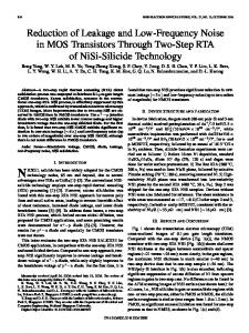
(a) (b) Fig. 1. Output luminance response to input signal. (a) CRT, (b) PDP.
low-gray level contour, plasma display panel. I.
INTRODUCTION
In the current display device market, plasma display panels (PDPs) and other large-sized displays for business and home use now are competing with CRTs, a widely used display device, for a market share. With the trend toward large-screen and flat-panel displays, PDPs have several advantages, such as a high brightness and contrast, luminous efficiency, wide viewing angle, and rapid refresh rate [1]. However, despite extensive plant investment by certain companies for the purpose of next-generation TV mass-production, many problems still need to be overcome, such as poor color and outline reproduction, dynamic false contours, and costperformance for consumer equipment. As such, a lot of recent research has been focused on solving these problems to facilitate the mass-production of PDPs, including the current study, which proposes an efficient error diffusion method for reducing low gray-level contours based on considering the actual emission characteristics of a PDP. As shown in Fig. 1, a PDP has a linear output luminance response to a digital-valued input [1], while a CRT has nonlinear input-output characteristics [2]. To compensate for the nonlinear transfer characteristics in a CRT, the input video signals of a television are gamma-corrected. Therefore, to produce images on a PDP that are equivalent to those on a 1
S.-J. Kang, H.-C. Do, J.-H. Shin, S.-I. Chien, and H.-S. Tae are with School of Electronic and Electrical Engineering, Kyungpook National University, Daegu, 702-701, Korea (corresponding author:
[email protected]). Contributed Paper Manuscript received February 12, 2004
Input
patterns, resulting in low gray-level contours [3]. There have already been various attempts to suppress low gray-level contours in a PDP using error diffusion or dithering [4]. Plus, a multi-luminance-level subfield method [3] was also recently developed to solve this problem. However, all these methods assume that the output luminance levels of a PDP increase uniformly, which means they usually fail to reduce the low gray-level contours effectively, as the actual output luminance levels of a PDP increase nonuniformly. Thus, for a more accurate inverse gamma correction, an error diffusion method is proposed that reflects the characteristics of the actual output luminance levels of a PDP. In addition, a 9subfield system including SF0 lower than the conventional SF1 is introduced to improve the low gray-level expression in a PDP. The remainder of this paper is organized as follows. Section II outlines the modeling of the output luminance of a PDP, then Section III provides a structural description and representation of the proposed 9-subfield system. Section IV introduces the proposed error diffusion method, and its performance is evaluated and compared to a conventional method in Section V. Finally, Section VI gives some conclusions. II. MODELING OF OUTPUT LUMINANCE OF PDP In a CRT, the intensity of the light emission is analogcontrolled by the strength of the electron beam striking the phosphor-coated screen. In contrast to the expression of a gray level in a CRT, the gray scale of a PDP is expressed by
0098 3063/04/$20.00 © 2004 IEEE
402
IEEE Transactions on Consumer Electronics, Vol. 50, No. 2, MAY 2004 Number of Sustain Pulse Pairs
Subfield #
99Subfield Subfield System System
SF1
SF2
SF3
SF4
SF5
SF6
2
4
8
16
32
64
SF7
SF8
128 256
SF0
SF1
SF2
SF3
SF4
SF5
SF6
SF7
SF8
1
2
4
8
16
32
64 128 256
Luminance li [cd/m 2]
2.32
3.30
5.2
9.0
16.5
30.8
59.3
109.8
203.8
Luminance Level B
1.344
1.912
3.013
5.216
9.562
17.85
34.37
63.63
118.1
Ideal luminance level
0.5
1
2
4
8
16
32
64
128
Fig. 2. Measured output luminance values in 4-inch test panel by CA100.
adjusting the number of sustain pulses. For example, to express a 256-level gray scale, the TV field (16.7 ms) is divided into 8 subfields and the output luminance levels for each subfield are 2n (0 ≤ n < 8). The human eye perceives a gray scale based on the temporal overlapping of the light intensity. To measure the output luminance levels of an actual PDP, a 4-inch test panel was used. The gas used in the 4-inch test panel was an He-Ne(7:3)-Xe(4%) mixture at a pressure of 400 Torr, plus the driving conditions were a sustain voltage of 180 V, sustain frequency of 200 kHz, address voltage of 60 V, and reset voltage of 390 V. The output luminance of the PDP was measured using a color analyzer CA-100. Figure 2 shows the luminance measured for each subfield. Here, luminance level B was normalized to 255 as its maximum value, with the exception of the luminance value during reset and address periods. The luminance level is different from the luminance for each subfield. As such, the luminance level is modeled based on the actual output luminance of the PDP, as expressed by (1).
L = L D + LR ≅
∑ ω i li + L R
(1)
i
1 where ω i = 0
if subfield i = ON
LD [cd/m 2 ]
∑i ωi li [cd/m2 ]
∑i ω i li − LD
All Subfield OFF
1.2
0
0
0
S1
4.5
3.3
3.3
0
S2
6.4
5.2
5.2
0
S1+ S2
9.6
8.4
8.5
0.1
S3
10.2
9.0
9.0
0
S1+ S3
13.4
12.2
12.3
0.1
S2+ S3
15.4
14.2
14.2
0 0.2
S1+ S2+ S3
18.5
17.3
17.5
S4
17.7
16.5
16.5
0
S1+ S4
21.1
19.9
19.8
-0.1
S2+ S4
22.7
21.5
21.7
0.2
levels up to 10. This model was verified on a scale of about ±0.2 cd/m2. III. 9-SUBFIELD SYSTEM In a conventional PDP driving scheme, the 256 gray levels are expressed by a combination of eight subfields. After the inverse gamma correction, the measured luminance levels of the PDP with a 8-subfield system are represented in Fig. 3, which clearly shows low gray-level contours, because the input signals between 0 and 20 correspond to only one output luminance level. Furthermore, the problem of false contours is serious for low gray levels, as the input gray levels between 0 and 50 only have six output luminance levels. Therefore, the current study adds one more subfield to the 8-subfield system to improve the low gray-level expression in a PDP. As such, in the case of a PDP using a sustain frequency of 200 kHz, two pulses are applied to each electrode, X and Y, to make the first subfield. Therefore, as shown in Fig. 4, the proposed 9subfield system includes an additional subfield with only one pulse, which is applied to each electrode, to express a 0.5gray-level. As shown in Fig. 2, the minimum expressible
if subfield i = OFF
8
where L is the luminance value measured on the actual PDP using the CA-100, LD is the luminance value during a sustain period, LR is the luminance value during a reset and address period, of which the effect has not been considered properly in traditional error diffusion modeling, and li is the luminance value measured for the i-th subfield period. Now, the luminance level is defined by
B=
L [cd/m 2 ]
L − LR × 255 LMAX − LR
(2)
where LMAX is the maximum luminance of the actual PDP and B is the luminance level. Table I shows the difference between the luminance value measured using the CA-100 (LD) and the luminance value calculated using (1) for low output gray-
Analog Method 8-Subfield System 9-Subfield System
7 Output Luminance Level
88Subfield Subfield System System
TABLE I DIFFERENCE BETWEEN MEASURED LUMINANCE VALUE AND CALCULATED LUMINANCE VALUE FOR LOW OUTPUT GRAY-LEVELS UP TO 10
6 5 4 3 2 1 0 0
10
20
30
40
50
Gamma Corrected Input Signal
Fig. 3. Available luminance levels after inverse gamma correction.
S.-J. Kang et al: Reduction of Low Gray-Level Contours Using Error Diffusion Based on Emission Characteristics of PDP
Subfield 1 (SF1) Subfield 0 (SF 0)
X
X
VS
Y
VS
Y
VS
VS
Z
Z 0
5 Time [µs]
0
10
5 Time [µs]
(a) (b) Fig. 4. Addition of subfield 0 in PDP using sustain frequency of 200 kHz.
luminance is 2.32 cd/m2 and the luminance level amounts to 1.3445 in the 9-subfield system. As a result, the low gray-level contours are improved based on increasing the number of output gray levels up to 11 instead of 6 levels in the 8-subfield system used to express the input gray levels between 0 and 50. IV.
PROPOSED ERROR DIFFUSION
For the inverse gamma correction, the input gray levels are transformed by the following equation.
x Y = k × 255
γ
(3)
where x is the input gray level and γ represents the predetermined gamma value. In (3), k denotes the maximum gray level representing the white point and Y is the ideal gray level for displaying input gray level x. However, the luminance level of the PDP is much restricted in this expression. Therefore, the inverse gamma-corrected value needs to be replaced with an expressible luminance level. The transformation is defined in a look-up table (LUT), which is determined by modeling the luminance level using the proposed 9-subfield system. To reduce the errors between the ideal gray level and the actual luminance level, the proposed error diffusion method is applied, as illustrated in Fig. 5. A. LUT for Modification of Luminance Levels In the error diffusion method, an LUT is needed to xi,j
Inverse Yi,j Gamma Correction
+
ui,j
LUT( ui,j )
+ Error Filter (w)
-
Bi,j
+
ei,j
Fig. 5. Flow chart for proposed error diffusion.
transform an ideal luminance level into an expressible one. In conventional methods, the whole process of determining the LUT and error diffusion is performed on the assumption that li increases twice. Namely, the low gray-level contour problem is dealt with assuming that the output luminance levels of the PDP increase equidistantly from 0 to 255 and that the output luminance level for each subfield is 2n (0 ≤ n < 8). However,
403
as shown in Fig. 2, the actual output luminance levels of a PDP do not increase equidistantly, because li does not increase twofold [5]. Namely, the actual output luminance levels of a PDP are different from the theoretical ones. Thus, if a PDP performs an inverse gamma correction assuming theoretical output luminance levels, when input signal 21 is entered, the PDP will expect that the output luminance level becomes 1 and only address the first subfield. However, an actual PDP will not display output luminance level 1, but rather output luminance level 1.912. Table II shows the quite substantial difference between the expected output luminance levels and the displayed ones when a PDP applies an inverse gamma correction. As such, there is no effective reduction of low gray-level contours, as the actual output luminance levels of a PDP do not increase equidistantly. Therefore, the LUT must be determined so that error diffusion method reflects the actual output characteristics of a PDP. In the proposed method, the LUT is defined according to the following procedure. First, all the actual luminance levels of the PDP are calculated by substituting the measured li into (1). Then, the LUT is determined by replacing the input luminance level with the nearest expressible luminance level. Table III shows part of a LUT determined using the proposed method, then Table IV shows a subfield selection algorithm that displays the modified luminance level according to the LUT.
TABLE II DIFFERENCE BETWEEN ACTUAL OUTPUT AND EXPECTED OUTPUT Expected Actual Error Input Analog signal output output (①) output (②) (② - ①) 0 1
0.000000 0.001295
0 0
0 0
0 0
2
0.005949
0
0
0
…
…
…
…
…
15
0.500671
1
1.912
0.912
16
0.577053
1
1.912
0.912
…
…
…
…
…
25
1.540351
2
3.013
1.013
26
1.679164
2
3.013
1.013
…
…
…
…
…
49
6.769914
7
10.142
3.142
50
7.077596
7
10.142
3.142
TABLE III PART OF LUT FOR MODIFICATION OF LUMINANCE LEVEL LUT (uij)
uij
LUT (uij)
0
4.642 – 5.071
4.926
0.672 – 1.628
1.344
5.071 – 5.743
5.216
1.628 – 2.463
1.912
5.743 – 6.415
6.270
2.463 – 3.135
3.013
6.415 – 6.844
6.560
3.135 – 3.808
3.257
6.844 – 7.679
7.128
3.808 – 4.642
4.358
……
……
uij 0 – 0.672
404
IEEE Transactions on Consumer Electronics, Vol. 50, No. 2, MAY 2004 TABLE IV SUBFIELD SELECTION ALGORITHM
Luminance level
of a recognizable image will correspond to a 2×2 pixel size. As such, the proposed error measure, which finds the error at position (i,j), is defined as the difference between the average value of the analog output luminance levels and that of the actual output luminance levels to the extent of a 2x2 pixel size, as defined by the following equations.
Subfield SF0
SF1
SF2
SF3
0 1.344
ON
1.912
ON
3.013
ON
3.257
ON
4.358
ON
4.926
1 1 1 1 1 1 Ei , j = ∑ ∑ Yi + k , j + l − ∑ ∑ Bi + k , j + l 4 k = 0 l =0 4 k =0 l =0
ON ON ON
ON
5.216
Eave =
ON
6.270
ON
ON
ON
B. Error Diffusion Based on Look Up Table After determining the LUT, the error diffusion method is applied. In the proposed method, an error is defined as the difference between the measured luminance value and the calculated luminance value. As shown in Fig. 5, the error is diffused to the unprocessed neighbor pixels after being multiplied with a certain weight. The specific procedure is represented through the following equations from (4) to (8).
1 MN
2
(9)
M −1 N −1
∑ ∑ Ei , j
(10)
i =0 j = 0
Here, B and Y are defined in (2) and (3), respectively, Ei,j is the error at position (i,j), and Eave is the average error value of an image with the size M × N. The proposed and conventional methods for reducing low gray-level contours were simulated using gradation images. Figures 6 and 7 show the simulation results and average error Eave, respectively. As shown in Fig. 6, the conventional error diffusion method failed to reduce the low gray-level contours, whereas the proposed method was successful. In particular, the 9-subfield system with error diffusion using the proposed method produced the best results.
2.2
Yi , j ui , j
xi , j = 255 × 255 = Yi , j + ∑ wk ,l ei − k , j − l k , l ∈R
(4) (5)
Bi , j = LUT (ui , j )
(6)
ei , j = ui , j − Bi , j
(7)
1/16 5 /16 3 /16 wi , j = * 7 /16
(8)
In these equations, subscript (i,j) is the pixel location. In (4), Y is the ideal gray level calculated from (3) when k = 255 and γ = 2.2. In (5), the modified output luminance level u is determined by adding the sum of the weighted error values to the analog inverse gamma corrected value. Then, the modified output luminance level B is determined by the LUT, as specified in (6). Thereafter, the error is determined by the difference between u and B, and diffused to the neighbor pixels by an error filter whose weights are defined by FloydSteinberg’s error diffusion coefficients [6]. In (8), the asterisk (*) indicates the currently processed pixel.
(a)
(b)
(c)
(d)
V. EXPERIMENTAL RESULTS A new error measure was set up to quantify the error between the output luminance levels of the proposed method and those of an analog method. Generally, the eye’s resolution is limited to roughly one minute of arc, a limitation that comes from the distribution of photoreceptors on the retina [7]. Therefore, human visual perception works based on the local mean luminance value of the surrounding area of a pixel, rather than a single luminance value. Thus, if an individual watches a 42-inch HDTV at a distance of 3 meters, the extent
(e) Fig. 6. Simulation results of inverse gamma correction on gradation images. (a) Analog method, (b) 8-subfield system without error diffusion method (ED), (c) 9-subfield system without ED, (d) 8-subfield system with ED, and (e) 9-subfield system with ED. Here, left and right images are inverse gamma corrected ones using conventional method and proposed method with LUT reflecting emission characteristics of PDP, respectively.
S.-J. Kang et al: Reduction of Low Gray-Level Contours Using Error Diffusion Based on Emission Characteristics of PDP
1.6 1.4 1.2
1.0
Conventional Method New Method 1.3248 1.0820
1.3009
0.8
0.6392
Eave
Eave
0.7677
0.6
0.8
0.4
0.6
0.2
Conventional Error Diffusion Method Proposed Error Diffusion Method
1.0560
1.0
0.4
405
0.3673 0.2168
0.2 0.1381
0.1108
0.0872
0.0346
0.0 8-Subfield 9-Subfield 8-Subfield without ED without ED with ED
0.0
9-Subfield with ED
Fig. 7. Comparison of average error values on gradation images.
In addition, the results for the proposed error measure, as shown in Fig. 7, confirmed a significant decrease in Eave when using the proposed method compared to the conventional one that assumed an equidistant condition in the luminance levels.
R Channel
0.0518
G Channel
0.0431
B Channel
Fig. 9. Comparison of average error values on rose images for three color channels.
simulation result when applying the conventional error diffusion method and 9-subfield system, which shows clear low gray-level contours. In contrast, there are almost no low gray-level contours in image (c) when using the proposed error diffusion method. Figure 9 reveals that Eave’s also decrease considerably when calculated from three color channels. VI. CONCLUSION
(a)
(b)
To systematically reduce image quality degradation due to low gray-level contours, the current paper proposed a 9subfield system using the error diffusion method based on the characteristics of a PDP. The proposed method modifies the ideal luminance level into an expressible one using the LUT and applies the error diffusion method to compensate for the difference between the modified luminance level and the luminance level of the input image. Simulations confirmed that the proposed 9-subfield system with error diffusion based on more realistic gray-level modeling was able to significantly suppress low gray-level contours in inverse gamma-corrected images on a PDP. REFERENCES [1] [2] [3]
(c) Fig. 8. Simulation results of inverse gamma correction on rose images. (a) Analog method, (b) Inverse gamma correction using conventional method on 9-subfield system and (c) inverse gamma correction using proposed method on 9-subfield system.
Figures 8 and 9 show the experimental results for the rose image in which gray levels are stretched up to 250 for a display purpose. In Fig. 8, the images on the right are enlargements of part of the images on the left. Image (b) is the
[4] [5]
[6] [7]
L. F. Webber, “The promise of plasma displays for HDTV,” in Proc. of Society for Information Display, pp. 714-717, Kobe, Japan, May 2000. C. Poynton, Digital Video and HDTV: Algorithms and Interfaces, Morgan Kaufmann Publishers, 2003, pp. 257-280. K.-D. Cho, H.-S. Tae, and S.-I. Chien, “Improvement of low gray scale linearity using multi-luminance-level subfield method in plasma display panel,” IEEE Trans. Consumer Electron., vol. 48, no. 3, pp. 377-381, Aug. 2002. T. Tokunaga, H. Nakamura, M. Suzuki, and N. Saegusa, “Development of new driving method for AC-PDPs,” IDW’99 Digest, pp.787-790, 1999. M. Yamada, M. Ishii, T. Shiga, and S. Mikoshiba, “A gray scale expression technique having constant increments of perceived luminance using a contiguous subfield scheme,” SID 02 DIGEST, pp. 940-943, 2002. R. Floyd and L. Steinberg, “An adaptive algorithm for spatial gray scale,” in Proc. of Society for Information Display, vol. 17, 1976. G. Berbecel, Digital Image Display: Algorithms and Implementation, Wiley, 2003, pp. 163-181.
406
IEEE Transactions on Consumer Electronics, Vol. 50, No. 2, MAY 2004 Sung-Jin Kang received the B.S.degree in electronic engineering from Kyungpook National University, Daegu, Korea, in 2003. He is currently working for the M.S. degree in electronic engineering at Kyungpook National University. His current research interests include computer vision and color image processing for display.
Hyun-Chul Do received the B.S. degree from Kyungil University, Gyeongsan, Korea, in 2000, and the M.S. degree from the Kyungpook National University, Daegu, Korea, in 2002. He is currently working for the Ph.D. degree in electronic engineering at Kyungpook National University. His current research interests include computer vision and color image processing for display.
Jung-Hwan Shin received the B.S. and M. S. degree in electronic engineering from Kyungpook National University, Daegu, Korea, in 1999 and 2001, respectively. He is currently working for the Ph.D. degree in electronic engineering at Kyungpook National University. His current research interests include computer vision, biometrics, evolutionary computation, and color image processing for display.
Sung-Il Chien received the B.S. degree from Seoul National University, Seoul, Korea, in 1977, and the M.S. degree from the Korea Advanced Institute of Science and Technology, Seoul, Korea, in 1981, and Ph.D. degree in electrical and computer engineering from Carnegie Mellon University in 1988. Since 1981, he has been with School of Electronic and Electrical Engineering, Kyungpook National University, Daegu, Korea, where he is currently a professor. His research interests are computer vision and color image processing for display. Dr. Chien is a member of IEEE and IEE, and also a member of the Society for Information Display (SID). Heung-Sik Tae received the B.S. degree in electrical engineering from Seoul National University, Seoul, Korea, in 1986 and M.S. degree and Ph.D. in plasma engineering from Seoul National University in 1988 and 1994, respectively. Since 1995, he has been as associate professor in School of Electronic and Electrical Engineering, Kyungpook National University in Daegu, Korea. His research interests include the optical characterization and driving circuit of plasma display panel, the design of millimeter wave guiding structure, and MEMS or thick-film processing for millimeter wave devices. Dr. Tae is a member of IEEE and also a member of the Society for Information Display (SID).