assess the effect of slew rate and final recovery time. ⢠provide a stable oscillation amplitude. Text. Nearly every electronic instrument needs an oscillator or ...
Punčochář, Mohylová: TELO, Chapter 13
13. Chapter: Relaxation oscillators Time of study: 4 hours Goals: the student should be able to •
describe basic relaxation structures
•
change time parameters of relaxation structures
•
assess the effect of slew rate and final recovery time
•
provide a stable oscillation amplitude
Text
Nearly every electronic instrument needs an oscillator or waveform generator of some sort. A very simple kind of oscillator (astable multivibrator, relaxation oscillator) can be made by charging and discharging a capacitor through a resistor – Fig. 1. The operation is simple.
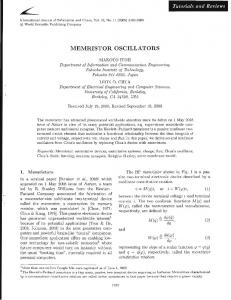
Fig.1. Op – amp relaxation oscillator – a); b) – output voltage; c) – capacitor voltage
Note 1) Final value of the capacitor voltage would be theoretically equal to ±Usat , if not working comparator input.
Punčochář, Mohylová: TELO, Chapter 13 Assume that when power is first applied, the op-amp output goes to positive saturation (+Usat). The capacitor C1 begins charging up toward +Usat, with time constant R1C1. When it reaches value U + H = U sat Ra ( Ra + Rb ) , the op-amp switches into negative saturation (-Usat) – it is a Schmitt trigger – and the capacitor begins discharging toward -Usat with the same time constant. When it reaches value U + D = − U sat Ra (Ra + Rb ) , the op-amp switches into positive saturation (+Usat), the capacitor C1 begins charging up toward +Usat. The cycle repeats indefinitely. And thus charging the capacitor in the interval T1 can be described by the equation uC1 (t ) = [uC1 (t = 0) − uC 1 (t → ∞)]⋅ exp( −t / τ 1 ) + uC1 (t → ∞) where (see Fig.1c) τ 1 = R1C1 uC1 (t = 0) = U + D = − U sat Ra (Ra + Rb ) uC1 (t → ∞) = +U sat . When uC1 (t ) reaches value U + H = U sat Ra ( Ra + Rb ) , the op-amp switches into negative saturation and t = T1 . From this we can determine U + H = [U + D − U sat ] ⋅ exp( −T1 / τ 1 ) + U sat ⇒ U + H − U sat = [U + D − U sat ]⋅ exp( −T1 / τ 1 ) ⇒ exp(T1 / τ 1 ) = [U + D − U sat ] [U + H − U sat ] ⇒
T1 = R1C1 ⋅ ln (1 + 2 Ra / Rb ) = Ra = Rb = 1,0986 ⋅ R1C1
Similarly, we determine that T2 = R1C1 ⋅ ln (1 + 2 Ra / Rb ) = Ra = Rb = 1,0986 ⋅ R1C1 and so the period is T = T1 + T2 = 2 ⋅ R1C1 ⋅ ln (1 + 2 Ra / Rb ) = Ra = Rb ≈ 2, 2 ⋅ R1C1 If saturation levels are unequal, we must (can) stabilize the output voltage amplitude – Fig.2. U sat = (U ZD + 2U D ) UZD
Fig.2. Stabilization of the output voltage amplitude UD
Punčochář, Mohylová: TELO, Chapter 13 Still is valid T = T1 + T2 = 2 ⋅ R1C1 ⋅ ln (1 + 2 Ra / Rb ) = Ra = Rb ≈ 2, 2 ⋅ R1C1 If we need T1 ≠ T2 , we can modify circuit in Fig.1 – see Fig.3. R2
D2 D1
Fig.3. A modification of the circuit on Fig. 3 by means of diodes D1,2
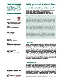
The diode D1 is switched for positive output voltage ( uo = +U sat ) and we can easy determine that T1 ≅ R1C1 ⋅ ln (1 + 2 Ra / Rb ) = Ra = Rb = 1,0986 ⋅ R1C1 . The diode D2 is switched for negative output voltage ( uo = −U sat ) and we can easy determine that T2 ≅ R2C1 ⋅ ln (1 + 2 Ra / Rb ) = Ra = Rb = 1,0986 ⋅ R2C1 . Thus T = T1 + T2 ≅ (R1C1 + R2C1 ) ⋅ ln (1 + 2 Ra / Rb ) = Ra = Rb ≈ 1,1 ⋅ ( R1C1 + R2C1 ) A better oscillator can be made by charging a capacitor through a current source – see Fig.4. The multivibrator consists of an integrator (OZ1) and a comparator (OZ2). The comparator compares the voltage Ud continuously with the inverting input that is at 0 V. When Ud goes above or below 0 V, the output of OZ2 is at the positive or negative saturation (±Usat), respectively. At this time Ud ≈ 0 V and up(t) = UPK and I1 = UPK/R1 -I2 = -uo(t)/R2 where up(t) is the triangular wave uo(t) is the square wave (see Fig.4).
Punčochář, Mohylová: TELO, Chapter 13
It is evident that for the ideal OZ2 (zero input currents) UPK/R1 = -uo(t)/R2 thus U PK = −(R 1/R 2 )u o (t) = ± (R1/R 2 )Usat
R2= 14,7kΩ
C = 1,2nF R OZ1
ITEGRATOR
R1= 10kΩ
I1
OZ2
Ud
I2 UO
COMPAR.
(R 1 /R 2 )U sat
iC(t) UP - (R 1 /R 2 )U sat
Fig.4: Square and triangular wave generator (multivibrator, supply voltage UCC is ± 15 V)
To work in the oscillation, the condition R1/R2 < 1 is necessary. On the contrary case the needed magnitude |UPK| will be greater than Usat, the circuit will not oscillate (if we suppose the same Usat of the OZ1 and the OZ2). Let us suppose that uo(t) = +Usat. This +Usat is an input of the integrator (inverting) OZ1 and a capacitor C current (for the ideal OZ1) is iC(t) = Usat/R = IC The output of the OZ1, therefore, will be a negative-going ramp. If uo(t) = -Usat the capacitor current iC(t) = -Usat/R = -IC the output of the OZ1, therefore, will be a positive-going ramp. The time it takes for the output waveform up(t) to swing from -(R1/R2)Usat to +(R1/R2)Usat is equal to half a time period T/2. Peak-to-peak amplitude of the triangular wave is ∆UPK = (R1/R2) Usat - [- (R1/R2) Usat] = 2. (R1/R2) Usat
Punčochář, Mohylová: TELO, Chapter 13 A change of a capacitor charge ∆QC (during T/2) is ∆QC = C. ∆UPK and ∆QC = IC.T/2 Hence IC.T/2 = C. ∆UPK thus (Usat/R).(T/2) = C. 2.(R1/R2)Usat or T = 4RC (R1/R2) The T is the time period of oscillations (ideal op amps). We can easy determine the frequency, too: f = 1/T = (R2/R1)/ (4RC) The integrator (OZ1) is "nearly ideal" if its slew rate SRI is greater than the maximum slope of the voltage up(t) - Fig.4: 2(R1/R 2 )Usat /(Tmin /2) ≤ SR
I
where Tmin is the needed minimum time period. Hence the needed SRI is given by (1/Tmin = fmax - the maximum needed frequency) SRI ≥ 4( R1 / R2 )U sat f max And on the contrary for the given SRI the "maximum ideal integrator frequency" is f max ≤ SR I /(4(R1/R 2 )U sat ) The comparator (OZ2) is ideal if its slew rate SRC is infinite and op amp recovery time tr is zero. In practice we must choose: SRC ≥ 10 ⋅ SRI See [2], too. Theoretical frequencies are in the Tab.1. Some practical measurements are in the Tab.2.
Punčochář, Mohylová: TELO, Chapter 13
R [kΩ] f [kHz] 2,2 139,18 10 30,620 100 3,062 1000 0,306 Tab. 1. Results from eq. f = 1/T = (R2/R1)/ (4RC) and given conditions OZ1
MAC156+
MAC156
MAA741 !
MAA741!
MAA741!
OZ2 tn [µs] tS [µs]
MAC157+ 0,4 0,4
MAC156 2 0,6
MAC157+ 0,4 0,4
MAC156 2 0,6
MAA741!!! 68 80
2,2 106,62 80,63 15,30 14,69 6,027 10 28,648 23,95 13,58 13,07 5,230 100 3,061 2,942 2,940 2,931 1,845 1000 0,301 0,301 0,301 0,301 0,300 R [kΩ] f [kHz] Tab.2. Measured properties of the circuit in Fig.4 (Usat≈13 V; UCC=±15V; tn- rise time; tS - decay time of OZ2; slew rate SRC ≈ 26/tn or 26/tS); + - optimum; ! -no good solution
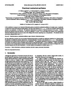
Poor dynamic properties of the comparator lead to overcharge of the capacity C (generate voltage ∆U above UPK) if R decreases, now ±UPK = (R1/R2) Usat+∆U This phenomenon leads to a decrease of frequency f with respect to its ideal value – tab.1. To overcome (partly) the effect of the op amp OZ2 slew rate (SRK) and overload recovery time (tr) we can modify the multivibrator - see a compensating resistor RK and a compensating capacitor CK in parallel to R1 -Fig.5. RK; 2k2
CK
iK
R2; 14k7 OZ2
I1
I2
R1; 12k uo(t)
uP(t) Fig. 5: A compensating circuit CK, RK
If we chose the right value of the CK the peak-to-peak amplitude of the triangular wave will be constant (with frequency; reduces effective value of R1 – it compensates ∆U). Tab.3 summarises the measured properties of the real multivibrator for CK = 0 (BEZ ≡ no capacitor CK), CK = 100 pF (nearly optimum) and CK = 330 pF ("overcompensation").
Punčochář, Mohylová: TELO, Chapter 13
R kΩ 2,2∗ 10 100 1000 CK
f kHz 106,6 28,65 3,061 0,301
Upp V 23,5 19 18,5 18 BEZ
f Upp kHz V 131,6 18,5 29,98 18,5 3,073 18,2 0,301 18 100 pF
f kHz 257,0 33,81 3,108 0,301
Upp V 10 16 17 18 330pF
Tab. 3. Measured real peak-to-peak capacitor amplitudes (Upp) and frequencies of oscillation (f) as a function of R and CK - Fig.5. [OZ1 - MAC156, OZ2 - MAC157; the MAC157 as an integrator is frequency unstable; ∗ - the op amps are hot due to a frequency dependent dissipation - switching losses - any touch of a finger can show up this "burning" problem].
If f > 200 kHz the MAC157 can temperature is above 90°C (8 pin metal can, TO-99). A junction-to-case thermal resistance of the TO-99 is 45°C/W (150 °C/W junction-to-ambient thermal resistance). It is evident that frequency 257 kHz will push the operating junction temperature high enough to concern. The instantaneous power dissipation during transition (in an op amp) may be quite large because voltage and current have high values simultaneously. With high repetition rate of f, the transistors (in the op amp) undergoes 2f transitions per second and so dissipates a much power, so some care should be made to ascertain if any power is frequency dependent. The lifetime of all semiconductors is inversely related to their operating junction temperature. The cooler semiconductors can be kept during operation, the more closely they will approach maximum useful live. To maintain low junction temperature, either thermal resistance (°C/W) or the power dissipated (or both) must be kept low. The useful output power (and the maximum useful frequency) is always limited by the cooling efficiency of op amp case. Even simple circuits with op amps can be expensive, if they are intended for processing fast signals specified in the frequency domain. Therefore we must decide which solution is best one for our purposes (heat sink, forced air movement, very high-speed op amps). And what about fast signals? It must be decided in agreement with "data sheets" for any chosen op amp.
Punčochář, Mohylová: TELO, Chapter 13
Basic texts [1] Punčochář, J.: Operační zesilovače v elektronice. BEN, Praha 2002 (5. vydání), čl. 76, čl. 79 [2] Punčochář, J.: Astable multivibrator with real op amps. http://www.elektrorevue.cz
Other text
Questions
1. How it is possible to suppress the effect of different op amp saturation voltages on function of relaxation circuit? 2. What is the amplitude of the integrator voltage depending on the finite slew rate and recovery time? 3. How can we correct the effect of finite slew rate (of comparator)? 4. Is a voltage to frequency converter a relaxation circuit?
' Answers you find in this text Problems
1. Design the circuit of Fig.1 for operation at 1 kHz. 2. Design the circuit of Fig.1 for operation at T1 = 0,5 ms and T2 = 4,5 ms. 3. Redesign the circuit of Fig. 4 for operation at 5 kHz. Select appropriate operational amplifiers (needed slew rates), suppose supply voltages ± 15 V and Usat = ± 13 V.
Punčochář, Mohylová: TELO, Chapter 13
Problems key Ad 1) Select for example R1 = Ra = Rb = 10 kΩ; then f = 1 / T = 1 / (2,2 ⋅ R1C1 ) ⇒ C1 = 1 / (2,2 ⋅ R1 ⋅ f ) = 45,5 nF. Ad 2) Select for example R1 = Ra = Rb = 10 kΩ; then T1 = 1,1 ⋅ R1C1 ⇒ C1 = T1 / (1,1 ⋅ R1 ) = 45,5 nF; then T2 = 1,1 ⋅ R2C1 ⇒ R2 = T2 / (1,1 ⋅ C1 ) = T2 ⋅ R1 / (1,1 ⋅ C1 ⋅ R1 ) = (T2 / T1 ) ⋅ R1 = 9 ⋅ R1 = 90 kΩ. Ad 3) Use eqs: f = 1/T = (R2/R1)/ (4RC) → needed R = (R2/R1)/(4fC) = 61250Ω; SRI ≥ 4( R1 / R2 )U sat f max → needed SRI > 4(10 / 14,7) ⋅ 13 ⋅ 5 ⋅ 103 = 0,177. 106 V/s = 0,177 V/μs; SRC ≥ 10 ⋅ SRI = 1,77 V/μs. (See tables 2 and 3, too). Recommendation
If you can solve and answer more than circa 60 % of the problems and questions, you may continue your study. 9. 1. 2013