a mobile ad hoc network with relaying nodes consists of looking down at the earth and representing it .... v(0) and assume that 0 ⤠u0 ⤠R and 0 ⤠v0 ⤠R. Let.
Relaying in Mobile Ad Hoc Networks: The Brownian Motion Mobility Model R.B. Groenevelt, E. Altman and P. Nain INRIA, 2004 route des Lucioles, 06902 Sophia Antipolis, France {robin.groenevelt, eitan.altman, philippe.nain}@sophia.inria.fr Abstract. Mobile ad hoc networks are characterized by a lack of a fixed infrastructure and by node mobility. In these networks data transfer can be improved by using mobile nodes as relay nodes. As a result, transmission power and the movement pattern of the nodes have a key impact on the performance. In this work we focus on the impact of node mobility through the analysis of a simple one-dimensional ad hoc network topology. Nodes move in adjacent segments with reflecting boundaries according to Brownian motions. Communications (or relays) between nodes can occur only when they are within transmission range of each other. We determine the expected time to relay a message and compute the probability density function of relaying locations. We also provide an approximation formula for the expected relay time between any pair of mobiles.
1
Introduction
Mobile ad hoc networks can be deployed when a fixed network structure is not available. As a consequence of the absence of a fixed infrastructure, the mobile components (or nodes) of an ad hoc network need to behave as routers by relaying messages in order to improve the performance of a network [7]. Instances of nodes in ad hoc networks are laptops, planes [12], cars, electronic tags on animals [11], mobile phones, et cetera. This has led to the design of protocols that take advantage of the node mobility (e.g. messaging applications in [8]).
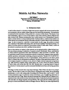
Data relaying cuts down transmission power, interferences and increases battery usage. On the other hand, it may increase latency—since the existence at any time of a “path” between two mobiles is not guaranteed—even if (intermediary) nodes can be used as routers to convey a message from its source to its destination. In this paper we study the impact of mobility on the latency in the case of nodes acting as relay nodes. This is done for one-dimensional ad hoc network topologies and under the assumption that nodes move according to (independent) Brownian motions. A natural approach (but not the only one, see [10] for another approach) to modeling a mobile ad hoc network with relaying nodes consists of looking down at the earth and representing it as a finite two-dimensional plane. If two mobiles are within a fixed transmission range of each other then a message can be relayed/transmitted (see Figure 1). Furthermore, mobiles move according to a certain movement pattern. Unfortunately, this simple model of an ad hoc network (no physical restrictions in the area covered by the nodes, nodes are homogeneous, etc.) is extremely difficult to analyze, even with simple movement patterns such as, for example, the Random Waypoint Mobility (RWM) model [14]. For instance, finding the stationary distribution of the location of the mobiles under the RWM is, to the best of our knowledge, an open problem.
Figure 1. Graphical representation of an ad hoc network. Nodes can transfer a message only if they are within each others transmission range. In this case only two nodes can communicate with each other.
Obtaining any results characterizing the first instance of time when two mobiles come within transmission range of each other is a problem of even greater complexity. For this reason, this paper focuses on a one-dimensional topology—a model that already reveals interesting properties. Its extension to two dimensions is an open problem.
When analyzing a mobile ad hoc network, an important consideration is the movement pattern. Are mobiles restricted in their movement by roads, physical objects, waterways, or mountains? Do they roam around a central point? It has been shown that the latter is the case for the RWM, where there is a higher concentration of mobiles around a central region [2]. The first version of this paper was presented in [6]. However, after its publication mistakes have been found which lead to the derivation of formulas which were a constant √ ( 2) off from the correct result. This paper contains the correct expressions. The following scenarios are addressed in this paper. In Section 2 we consider the situation where two mobiles move along a segment with reflecting boundaries (see Figure 2). Both mobiles move along the segment according to independent Brownian motions. We are interested in computing the expected time until both mobiles come within communication range of each other. This quantity is computed for any given initial locations (Proposition 1) as well as for the case where each Brownian motion is initially in steadystate (Proposition 3). It is known (see Section 3) that the latter assumption implies that both mobiles are uniformly distributed over the segment. The uniform spatial distribution over the coverage area has attracted attention lately and several fundamental results [1, 7] have been obtained in this setting. However, our model is different from the models considered in those papers. In Section 3, we consider I mobiles and I segments, one mobile per segment, as depicted in Figure 5. The mobiles move along their respective segment (with reflecting boundaries) according to independent Brownian motions. The goal is to determine the expected transfer time between the first and last mobile in the sequence (Proposition 5). As an additional result, we identify the probability density function (pdf) of the position of a mobile at a relay epoch (Proposition 4). Numerical results are reported in Section 4. These results suggest an accurate and scalable approximation for the expected transfer time (see equation (15)). The possible extensions of the model are discussed in Section 5.
2
Two mobiles moving along a line segment
We consider two mobiles (say mobiles X and Y ) moving along segment [0, L]. See Figure 2. Communications between these two mobiles occur only when the distance between them is less than or equal to r ≤ L. The objective of this section is to determine the expected transfer time, defined as the first time when both mobiles come with a distance r of each other. 0
r L
r
x0
y0
Figure 2. Two mobiles moving along [0, L] with transmission range r.
Let x(t) and y(t) be the position of mobiles X and Y , respectively, at time t. We assume that X = {x(t), t ≥ 0} and Y = {y(t), t ≥ 0} are identical and independent Brownian motions with drift 0 and diffusion coefficient1 D, both moving along the segment [0, L] with reflecting boundaries at the edges. Let TL,r be the transfer time, namely,
TL,r = inf{t ≥ 0 : |y(t) − x(t)| ≤ r}.
(1)
Set x(0) = x0 and y(0) = y0 . By convention we assume that TL,r = 0 if |y0 − x0 | ≤ r. From now on we assume that |y0 − x0 | > r. We are interested in
TL,r (x0 , y0 ) := IE[TL,r | x(0) = x0 , y(0) = y0 ],
0 < x0 , y0 < L,
the expected transfer time given that mobiles X and Y are located at position x0 and y0 , respectively, at time t = 0. The following result holds:
1
i.e x(t + h) − x(t) (respectively y(t + h) − y(t)) is normally distributed with mean 0 and variance 2Dh for all h > 0, and non-overlapping time intervals are independent of each other.
Proposition 1 (Expected transfer time with given initial positions). For 0 ≤ x0 < y0 ≤ L with x0 + r < y0 and 0 ≤ r ≤ L TL,r (x0 , y0 ) =
32(L − r)2 Dπ 4
∞ X
∞ X
sin
m≥1 n≥1 m odd n odd
�
mπ(y0 +x0 −r) 2(L−r)
�
sin
�
nπ(y0 −x0 −r) 2(L−r)
mn(m2 + n2 )
�
.
(2)
� The proof of Proposition 1 is based on the following intermediary result that gives the expected time for a two-dimensional Brownian motion Z evolving in a R by R square to hit any boundary of the square. Proposition 2 (Two Brownian motions in a square). Consider two independent and identical one-dimensional Brownian motions {u(t), t ≥ 0} and {v(t), t ≥ 0}, with zero drift and diffusion coefficient D. Define the twodimensional Brownian motion Z = {z(t) = (u(t), v(t)), t ≥ 0}. Set u 0 = u(0) and v0 := v(0) and assume that 0 ≤ u0 ≤ R and 0 ≤ v0 ≤ R. Let τR := inf{t ≥ 0 : u(t) ∈ {0, R} or v(t) ∈ {0, R}} be the first time when the process Z hits the boundary of a square of size R by R. Define τR (u0 , u0 ) = IE[τR | z(0) = (u0 , v0 )]. Then, � � ∞ ∞ 0 0 sin nπv 16R2 X X sin mπu R R . τR (u0 , v0 ) = Dπ 4 m≥1 n≥1 mn(m2 + n2 ) m
odd
n
(3)
odd
� The proof of Proposition 2 is given in Appendix A. We are now in a position to prove Proposition 1. Proof of Proposition 1. Let x0 + r < y0 ≤ L. An equivalent way to view the Brownian motions X and Y at time t = 0 is to consider that the point (x0 , y0 ) is located in the upper triangle in
Figure 3 delimited by the lines x = 0, y = L and y = x + r. If we assume that the boundaries x = 0 and y = L are reflecting boundaries in Figure 3, then we see that TL,r (x0 , y0 ) is nothing but the expected time needed for the two-dimensional Brownian motion {(x(t), y(t)), t ≥ 0} to hit the diagonal of the triangle (i.e. to hit the line y = x+r) given that (x(0), y(0)) = (x0 , y0 ). (The process {(x(t), y(t)), t ≥ 0} is a two-dimensional Brownian motion since {x(t), t ≥ 0} and {y(t), t ≥ 0} are both independent Brownian motions.) By using the classical method of images (see e.g. [9, p. 81]), it can be seen that this time is itself identical to the expected time needed to hit the boundary of the square of √ √ size 2(L − r) by 2(L − r) shown in Figure 4 given that (x(0), y(0)) = (x0 , y0 ). This is due to the reflecting boundaries at x = 0 and y = L acting as mirrors. In order to apply the result in Proposition 2, we need to compute the coordinates (x00 , y00 ) of (x0 , y0 ) in a new system of coordinates (x0 , y 0 ) depicted in Figure 4 and which √ is rotated 45o from the original coordinate system. We find (x00 , y00 ) = ((y0 + x0 − r)/ 2 √ and (y0 − x0 − r)/ 2) and we may conclude, from Proposition 2, that � √ √ � TL,r (x0 , y0 ) = τ√2(L−r) (y0 + x0 − r)/ 2, (y0 − x0 − r)/ 2 .
(4)
By using (3) in the right hand side of (4) we see that (2) holds.
An example of the expected transfer time TL,r (x0 , y0 ) is displayed in Figure 6 (see Section 4 for comments). We conclude this section by giving the expected transfer time when both mobiles are uniformly distributed over the segment [0, L] at time t = 0. We will see in the next section that this case corresponds to the situation where both Brownian motions X and Y are in steady-state at time t = 0. Proposition 3 (Expected transfer time for uniform initial positions). Assume that both mobiles X and Y are uniformly distributed over [0, L] at time t = 0 and 0 ≤ r ≤ L. The expected transfer time IE[TL,r ] is
Absorbing boundary
Reflecting boundary
Absorbing boundary �
L
�
��
(xo ,yo )
yo
�������� ��
L � �
�� ����������������� � �
Absorbing boundary
Reflecting boundary
����
��������������� � �
r
r
0
�
Absorbing boundary
Absorbing boundary 0
xo
L Reflecting boundary
Figure 3. When mobiles X and Y are at a distance r of each other they are located on the line y = x + r (y0 > x0 + r).
IE[TL,r ] =
where C0 is a constant given by C0 =
L
� �
Figure 4. Since reflecting barriers at x = 0 and y = L act as mirrors, the method of images turns the problem into a 2D Brownian motion inside four absorbing barriers.
128(L − r)4 C0 , Dπ 6 L2
P∞
m=1 m odd
P∞
(5)
1 n=1 2 2 2 2 n odd m n (m +n )
≈ 0.52792664.
Proof. Since X and Y are uniformly distributed at t = 0, we have
IE[TL,r ] = = = =
Z LZ L 1 IE[TL,r | x(0) = x0 , y(0) = y0 ]dx0 dy0 L2 0 0 Z Z 1 1 TL,r (x0 , y0 ) dx0 dy0 + 2 TL,r (y0 , x0 ) dx0 dy0 L2 x0 +r