Apr 15, 2012 - show that it leads to significant system ability to detect and correct insertios/deletions. ... concatenated coding, error-correction coding, insertion/deletion .... to the sparsified messages (denote it by s) and w + s be sent over the channel. .... Thus, in the label of each signal point, one bit (can be any of the m + 1 ...
1
Reliable communication over non-binary insertion/deletion channels Raman Yazdani, Student Member, IEEE, and Masoud Ardakani, Senior Member, IEEE
arXiv:1204.3238v1 [cs.IT] 15 Apr 2012
Department of Electrical and Computer Engineering, University of Alberta Edmonton, Alberta, T6G 2V4, Canada {yazdani, ardakani}@ece.ualberta.ca
Abstract We consider the problem of reliable communication over non-binary insertion/deletion channels where symbols are randomly deleted from or inserted in the transmitted sequence and all symbols are corrupted by additive white Gaussian noise. To this end, we utilize the inherent redundancy achievable in non-binary symbol sets by first expanding the symbol set and then allocating part of the bits associated with each symbol to watermark symbols. The watermark sequence, known at the receiver, is then used by a forwardbackward algorithm to provide soft information for an outer code which decodes the transmitted sequence. Through numerical results and discussions, we evaluate the performance of the proposed solution and show that it leads to significant system ability to detect and correct insertios/deletions. We also provide estimates of the maximum achievable information rates of the system, compare them with the available bounds, and construct practical codes capable of approaching these limits.
Index Terms concatenated coding, error-correction coding, insertion/deletion channels, watermark codes, hidden Markov models (HMM)
I. I NTRODUCTION Since the seminal work of Shannon [1], there have been huge advancements in coding and information theory. The fundamental limits and efficient coding solutions approaching these limits are now known for many communication channels. However, in the vast majority of coding schemes invented, it is assumed that the receiver is perfectly synchronized with the transmitter, i.e., the symbol arrival times are known at
2
the receiver. In most communication systems, however, achieving perfect synchronization is not possible even with the existence of timing recovery systems. When perfect synchronization does not exist, random symbol insertions and deletions (synchronization errors) occur in the received sequence. This phenomenon poses a great challenge for error correction. Since the positions of the inserted/deleted symbols are unknown at the receiver, even a single uncorrected insertion/deletion can result in a catastrophic burst of errors. Thus, conventional error-correcting codes fail at these situations. Error-correcting codes designed for dealing with such insertion/deletion (I/D) channels are called synchronization codes. Synchronization codes have a long history but their design and analysis has proven to be extremely challenging, hence few practical results exist in the literature. Moreover, standard approaches do not lead to finding the optimal codebooks or tight bounds on the capacity of I/D channels and finding their capacity is still an open problem [2]. The first synchronization code was proposed by Sellers in 1962 [3]. He inserted marker sequences in the transmitted bitstream to achieve synchronization. Long markers allowed the decoder to correct multiple insertion or deletion errors but greatly increased the overhead. In 1966, using number-theoretic techniques, Levenshtein constructed binary codes capable of correcting a single insertion or deletion assuming that the codeword boundaries were known at the decoder [4]. Most subsequent work were inspired by the number-theoretic methods used by Levenshtein, e.g., see [5]–[8]. Unfortunately, these constructions either cannot be generalized to correct multiple synchronization errors without a significant loss in rate, do not scale well for large block lengths, or lack practical and efficient encoding or decoding algorithms. Some authors also generalized these number-theoretic methods to non-binary alphabets and constructed non-binary synchronization codes [9]–[13]. Following [12], perfect deletion-correcting codes were studied and constructed using combinatorial approaches [14]–[16]. Most of these codes, however, are constructed using ad hoc techniques and no practical encoding and decoding algorithm is provided. Non-binary lowdensity parity-check (LDPC) codes decoded by a verification-based decoding algorithm are designed for deletion channels in [17]. Unfortunately, the decoding complexity of this construction is also far from being practical. The drawback of all the above-mentioned synchronization codes is that they only work under very stringent synchronization and noise restrictions such as working only on deletion channels, or a single synchronization error per block. Coding methods proposed for error-correction on the I/D channels working under more general conditions are usually based on concatenated coding schemes with two layers of codes, i.e., an inner and an outer code [18]–[22]. The inner code identifies the positions of the synchronization
3
errors and the outer code is responsible for correcting the insertions, deletions, and substitution errors as well as misidentified synchronization errors. In the seminal work of Davey and MacKay [19], a practical concatenated coding method is presented for error-correction on general binary I/D channels. They have called their inner code, a watermark code. The main idea is to provide a carrier signal or watermark for the outer code. The synchronization errors are inferred by the outer code via identifying discontinuities in the carrier signal. One of the advantages of watermark codes is that the decoder does not need to know the block boundaries of the received sequence. However, due to the use of a sparsifier, rate loss is significant. The watermark is substituted by fixed and pseudo-random markers in [21] and is shown that it allows better rates but is only able to outperform the watermark codes at low synchronization error rates. Also, it has recently been shown that the performance of watermark codes can be improved by using symbol-level decoding instead of bit-level decoding [23], [24]. In this work, we consider the problem of devising an efficient coding method for reliable communication over non-binary I/D channels. On these channels, synchronization errors occur at the symbol level, i.e., symbols are randomly inserted in and deleted from the received sequence. We also assume that all symbols are corrupted by additive white Gaussian noise (AWGN). The use of this channel model is motivated by the fact that at the receiver the received continuous waveform is first sampled at certain time instances to produce the discrete symbol sequence required by the decoder. If the symbol arrival times are not perfectly known at the receiver, i.e., there is timing mismatch, some of the transmitted symbols are not sampled at all (symbol deletions) or sampled multiple times (symbol insertions) [25]. As a result, this channel model can be used to represent non-binary communications over the AWGN channel suffering from timing mismatch. Most communication systems use non-binary signalling, where synchronization errors can result in insertion/deletion at the symbol level. For the proposed channel model, we utilize the inherent redundancy that can be achieved in non-binary symbol sets by first expanding the symbol set and then allocating part of the bits associated with each symbol to watermark symbols. As a result, not all the available bits in the signal constellation are used for the transmission of information bits. In its simplest form, our solution can be viewed as a communication system using two different signal sets. The system switches between these two signal sets according to a binary watermark sequence. Since the watermark sequence is known both at the transmitter and the receiver, probabilistic decoding can be used to infer the insertions and deletions that occurred and to remove the effect of additive noise. In particular, the system is modeled by a hidden Markov model (HMM) [26] and the forward-backward algorithm [27] is used for decoding.
4
Our proposed scheme resembles trellis coded modulation (TCM) [28]. The main idea in both methods is to add redundancy by expanding the symbol set and limit the symbol transitions in a controlled manner. The proposed method is also closely related to the watermark codes of [19]. In both methods, decoding is done by the aid of a watermark sequence which both the transmitter and receiver agree on. The difference is that the extra degree of freedom in non-binary sets allows us to separate information from the watermark. Our proposed solution leads to significant system ability to detect and correct synchronization errors. For example, a rate 1/4 binary outer code is capable of correcting about 2, 900 insertion/deletion errors per block of 10, 012 symbols even when block boundaries are unknown at the receiver. This paper is organized as follows. In Sections II and III, we state our proposed approach and describe the system model. Section IV demonstrates the capabilities of the proposed solution by providing numerical results and discussions. Section V describes ways to increase the achievable information rates on the channel and Section VI analyzes the system in terms of complexity, and practical considerations. Finally, Section VII concludes the paper. II. C HANNEL
MODEL AND THE PROPOSED APPROACH
Throughout this paper, scalar quantities are shown by lower case symbols, complex quantities by boldface letters, and vectors by underlined symbols.
A. Channel model The channel model we consider in this work is a non-binary I/D channel with AWGN where insertions and deletions occur at the symbol level. Similar to [19], it is assumed that the symbols from the input sequence x first enter a queue before being transmitted. Then at each channel use, either a random symbol is inserted in the symbol sequence x′ with probability pi , the next queued symbol is deleted with probability pd , or the next queued symbol is transmitted (put as the next symbol in x′ ) with probability pt = 1−pd −pi .
For computational purposes, we assume that the maximum number of insertions which can occur at each channel use is I . The resulting symbol sequence x′ is finally affected by an i.i.d. sequence of AWGN z where z ∼ CN (0, 2σ 2 ) and y = x′ + z is received at the receiver side. Note that in this paper, to show the capabilities of the proposed method, we consider totally random and independent symbol insertions/deletions. When symbol insertions are resulted from imperfect synchronization, insertions or deletions tend to be correlated. These cases lead to easier identification of insertions/deletions at the receiver compared to random independent insertions/deletions which we consider here.
5
B. Proposed approach Now, consider a communication system working on this channel by employing an M -ary signalling (e.g., M -ary phase-shift keying (PSK)). We call this the base system. Motivated by the idea of watermark codes [19], we are interested in embedding a watermark in the transmitted sequence. The watermark, being known at the receiver, allows the decoder to deduce the insertions and deletions and to recover the transmitted sequence. The watermark can be embedded in the transmitted sequence in many ways. One way of doing this is to add the watermark to the information sequence and treat the information sequence as additive noise at the receiver. This is a direct extension of the binary watermark codes of [19] to non-binary signalling. In particular, the additive watermark w can be defined as a sequence of M -ary symbols drawn from the base system constellation. The binary information sequence is first passed through a sparsifier; every k bits of the information sequence is converted to an n-tuple of M -ary symbols. The rate of the sparsifier is then given by rs = k/n where 0 < rs < m and M = 2m . The average density of the sparsifier f is defined as the average Hamming distance of the n-tuples divided by n. The mapping used in the sparsifier is chosen as to minimize f . By defining addition as shifting over the constellation symbols, the watermark sequence could be added to the sparsified messages (denote it by s) and w ⊕ s be sent over the channel. At the receiver, similar to [19], an inner decoder which knows the watermark sequence, uses the received sequence to deduce the insertions/deletions and provides soft information for an outer code. The main drawback of this method is that the decoder is not able to distinguish between additive noise and the information symbols. This is because the information is embedded into the watermark by adding s to w. Sequence s contains both zeros and non-zero symbols. Non-zero symbols shift the watermark
symbols over the constellation, similar to what additive noise does. This greatly degrades the performance of the decoder. To improve the decoding performance, s should contain as many zeros as possible, i.e., be as sparse as possible, which is equivalent to having a small f . A small f is achieved by decreasing rs which in turn decreases the achievable rates on the channel directly. Also, notice that even in the absence of additive noise, the decoder is still fooled by the shifts occurred over w and thus misidentifies some of the insertions/deletions. To aid error recovery at the receiver, we are interested in an embedding method which makes the watermark as distinguishable as possible from the information sequence. This necessitates using some extra resources (other than those used to transmit the information sequence) for transmitting the watermark
6
sequence. These extra resources can be provided by enlarging the signal set. The extra available bits per transmission can then be used to transmit the watermark. After embedding the watermark, we refer to the system as the watermarked system. In this work, we are mostly interested in binary watermark sequences. As a result, to accommodate the watermark bits in each symbol, we expand the signal set size M by the factor of 2, giving rise to a 2M -ary signalling scheme. For example, if the base system uses 4-PSK, in the watermarked system we use 8-PSK modulation. To provide fair comparison, we put the symbol rate, information bits per symbol (denoted by rc ), and average energy of the signal constellation of the watermarked system equal to those of the base
system. As a result, the spectral efficiency and the total transmitted power of the watermarked system are equal to those of the base system. In other words, no bit rate, bandwidth, or power is sacrificed as a result of embedding the watermark. Notice that rc = m where M = 2m for the base system and also the watermarked system when a binary watermark sequence is used for each transmitted symbol. This is because in an M -ary base system all the m available bits are dedicated to information bits. Also, in each symbol of the 2M -ary watermarked system
(with m + 1 available bits) m bits are assigned to information bits. Later, we will see that sometimes it is more efficient to use non-binary watermark sequences or to assign less than one bit per symbol on average to the watermark giving rise to 0 < rc < m + 1. These cases will be investigated in Section V. Expanding the signal set while fixing the average energy of the constellation leads to reduction in the minimum distance of the constellation. Nevertheless, we show that by using the mapping described in Section III-A, the minimum distance dmin between symbols corresponding to the same watermark value does not necessarily reduce. In fact in some cases, e.g., in PSK modulation, the minimum distance does not change compared to the base system. Thus, the noise immunity1 of the system does not change after adding the watermark. III. S YSTEM
MODEL
The proposed system model is shown in Fig. 1. First, the binary information sequence b is encoded by the outer code producing the coded binary sequence d which is then broken into m-bit subsequences. The modulator then combines the binary watermark w and the m-bit subsequences by a one-to-one mapping µ : {0, 1}m+1 → X where X is the signal set of size |X | = 2M = 2m+1 . Then x is sent over the channel. 1
Here, the noise immunity is measured in the absence of synchronization errors under the assumption of minimum distance
decoding. As a result, the minimum distance between the signal constellation points can be used as the noise immunity measure.
7
b
Outer Encoder
d
x
Modulator
w
Ins/del Channel z
ˆb
Outer Decoder
l
Watermark Decoder
y
w Fig. 1.
The proposed system model.
The received sequence y is first decoded by the watermark decoder which provides soft information for the outer decoder in terms of log-likelihood ratios (LLRs). The LLR sequence l is then utilized to decode the information sequence ˆb. A. Modulator The modulator plays a key role in the proposed system. It allows embedding encoded data and watermark bits while ensuring a good minimum distance. The most important part of designing the modulator is to choose an appropriate mapping µ. By viewing µ as {0, 1} × {0, 1}m → X , we first divide X into two disjoint subsets X 0 and X 1 each having M signal points corresponding to watermark bit w = 0 and w = 1, respectively. Thus, in the label of each signal point, one bit (can be any of the m + 1 bits) is dedicated to the watermark bit and the other m bits correspond to the m-bit subsequences of d. Formally we have X w = {x|x ∈ X ; ℓw (x) = w} ,
for
w = 0, 1,
where ℓw (x) denotes the value of the bit in the label of x dedicated to the watermark. We also define ℓj (x) for j = 1, 2, . . . , m as the j -th non-watermark bit of the label of x.
Now the question is how to choose the labeling. To maximize the noise immunity of the system, and since the watermark sequence is known at the receiver, we maximize the minimum distance between the
8
Q
Q
100
00 0 01
0 00 dmin
dmin
110
10
I
I
1 01
01
0 10
011 111
11
(b) Watermarked system
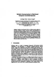
(a) Base system Fig. 2.
Signal constellations and their labeling for the base system (4-PSK) and the watermarked system (8-PSK). The leftmost √ bit in the label of the watermarked system corresponds to the watermark bit. For both constellation dmin = 2.
signal points in each of X 0 and X 1 . To do this, first we do a one-level set partitioning [28], i.e., we divide X into two subsets with the largest minimum distance between the points in each subset. These subsets are
named X 0 and X 1 and the watermark bit of the label is assigned accordingly. Next, by a Gray mapping [29] of the signals in each of X 0 and X 1 , the non-watermark bits of the label are assigned. This process is illustrated for two different signal constellations in Figs. 2 and 3. The Gray mapping ensures the least bit error rate in each subset [29]. The minimum distance of the constellation is now defined as dmin = min
min
w {xi ,xj }⊂X w ,xi 6=xj
||xi − xj ||.
Notice that by assuming signal constellations of fixed energy, going from M -PSK in the base system to 2M -PSK in the watermarked system does not change dmin (see Fig. 2). For the QAM, as illustrated in
Fig. 3, dmin does change because of energy adjustments but always stays very close to that of the original constellation. For example in Fig. 3, dmin is reduced by only 2.4%. A definition which proves useful in the next sections is � Xj (wi , di,j ) = x|x ∈ X ; ℓw (x) = wi , ℓj (x) = di,j ,
where i denotes the index of both the watermark bit and the m-bit subsequences of d and di,j = d(i−1)m+j
9
10000
Q
0000
0100
1100
00000
1000
0101
1101
1001
Q 11100
0 0001 1 0011
11000 01100
00100 10101
10001
0001
10100
11101 00101
1 0111
01000
11001
01101 11111
01001 I
11011
I
0011
0111
1111
1011
00011 10010
0010
0110
1110
1010
1 0110 00010
01111
0 0111 11110 0 0110
11010
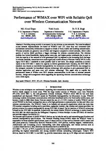
Fig. 3.
01010
01110
dmin
(a) Base system
01011
dmin
(b) Watermarked system
Signal constellations and their labeling for the base system (16-QAM) and the watermarked system (32-AM/PM). The
leftmost bit in the label of the watermarked system corresponds to the watermark bit. Both constellation have unit average energy. √ √ Thus, dmin = 2/ 10 = 0.633 for the base system and dmin = 4/ 42 = 0.617 for the watermarked system.
denotes the j -th bit of the i-th subsequence. Considering a watermark sequence of length N and an encoded data sequence of length mN , then i = 1, 2, . . . , N . Thus, Xj (u, v) refers to the subset of X where the watermark bit wi is equal to u and the j -th data bit in the i-th subsequence, i.e., di,j , is equal to v . The size of this subset is M/2. B. Watermark decoder The goal of the watermark decoder is to produce LLRs for the outer decoder given w and the received sequence y . As in [19], by ignoring the correlations in d, we can use an HMM to model the received sequence and then use the forward-backward algorithm [26] to calculate posterior probabilities or LLRs for the outer decoder. Notice that due to the nature of the channel which introduces insertions and deletions, there will be a synchronization drift between x and y . The synchronization drift at position i, i.e., ti is defined as the (number of insertions) − (number of deletions) occurred in the signal stream until the ith symbol, i.e., xi , is ready for transmission2 . The drifts {ti }N i=1 , form the hidden states of the HMM. Each 2
This means that if xi−1 is not deleted by the channel it is received as y i−1+ti .
10
state ti takes values from T = {. . . , −2, −1, 0, 1, 2, . . . }.
(1)
Thus, ti performs a random walk on T whose mean and variance depend on pi and pd . To reduce the decoding complexity, as in [19], we limit the drift to |ti | ≤ tmax where tmax is usually chosen large enough such that it accommodates all likely drifts with high probability. For example, when pi = pd , tmax p is chosen several times larger than N pd /(1 − pd ) which represents the standard deviation of the drifts over a block of size N .
To further characterize the HMM [26], we need the state transition probabilities, i.e., Pab = P (ti+1 = b|ti = a). Each symbol xi entering the channel can produce any number of symbols between 0 and I + 1
at the channel output. As a result, if ti = a, then ti+1 ∈ {a − 1, . . . , a + I}. Notice that the transition from ti = a to ti+1 = b can occur in two ways. One is when xi is deleted by the channel and (b − a + 1) symbols are inserted by the channel. The other one is when xi is transmitted and (b − a) symbols are inserted by the channel. In either case, (b − a + 1) symbols are produced at the channel output. As a result, the state transition probabilities are given by pd αI pi pd + pt Pab = pt ) pd + pb−a αI (pb−a+1 i i α pI p I i t 0
b=a−1 b=a
(2)
a