Journal of Power Sources 396 (2018) 304–313
Contents lists available at ScienceDirect
Journal of Power Sources journal homepage: www.elsevier.com/locate/jpowsour
Remedies of capacity fading in room-temperature sodium-sulfur batteries 1
T
∗
1
Y.X. Ren , H.R. Jiang , T.S. Zhao , L. Zeng, C. Xiong HKUST Energy Institute, Department of Mechanical and Aerospace Engineering, The Hong Kong University of Science and Technology, Clear Water Bay, Kowloon, Hong Kong SAR, China
H I GH L IG H T S
PBI membrane is employed to suppress polysulfide crossover for Na-S batteries. • The and insulating Na S is determined as the final discharge product. • Insoluble can complex with Na S to improve the precipitation kinetics. • PTheS chemical mediation of I / I promotes the dissolution of Na S . • A much improved capacity retention is attained (92.9% for 50 cycles at 0.2C). • 2 2
2 5
2 2
−
− 3
2 2
A R T I C LE I N FO
A B S T R A C T
Keywords: Na-S battery Shuttle effect Discharge product Separator Electrolyte additive
Liquid-electrolyte sodium-sulfur battery operated at room temperature is encountering challenges brought by the complex sulfur redox reactions, including (i) the dissolved polysulfide intermediates trigger serious side reactions on Na anode surface; (ii) the short-chain sulfide precipitation exhibits sluggish kinetics and the sulfur utilization is generally below 50% with unclear reasons. In this work, employing an ion selective polybenzimidazole-based separator we successfully suppress the polysulfide corrosion on the Na anode, which allows the investigation of the precipitation reaction. Combining DFT calculation and characterization techniques, we determine Na2S2 particles as the final discharge product and reveal that Na2S2 passivation is the predominant attributes of large polarization and capacity fading. To address these issues, we present the use of a bifunctional NaI-P2S5 based electrolyte additive, which (i) improves the Na2S2 precipitation kinetics by forming soluble Na2S2-P2S5 complex and (ii) promotes the dissolution of Na2S2 by the chemical mediation of I−/ I3− . As a result, a much improved capacity retention (92.9% for 50 cycles at 0.2C) is attained, which sheds light on enabling the stable operation of sodium-sulfur batteries via combining advanced separator and electrolyte engineering strategies.
1. Introduction For storing the fluctuating electricity generated by solar panels and wind turbines, alkaline metal based batteries have been proposed to meet the demand of high energy density. Electrochemical energy storage with the sodium (Na) and sulfur (S) chemistries is especially appealing as it well caters the low-cost and high-energy targets desired by the distributed grids. Success has been achieved by the high-temperature molten Na-S battery (> 300 °C) using the solid electrolyte [1–6]. Though promising in terms of power/energy densities and high efficiency with long cycle life, safety concern arising from high operating temperature as well as the complex system design to store the highly reactive molten Na and S species directly prohibits its extensive
∗
1
Corresponding author. E-mail address:
[email protected] (T.S. Zhao). These authors contributed equally to this work.
https://doi.org/10.1016/j.jpowsour.2018.06.056 Received 6 April 2018; Received in revised form 10 May 2018; Accepted 11 June 2018 0378-7753/ © 2018 Elsevier B.V. All rights reserved.
application. Lowering the operating temperature of the Na-S battery has been recognized as a meaningful topic that will affect this technology, developing the room-temperature (RT) Na-S battery into reliable, low-cost, scaled-up energy storage systems thus has attracted everincreasing research interest [7–12]. Liquid electrolyte with a high ionic conductivity is employed in the RT Na-S battery. During the discharge process, Na stripping occurs at the anode, resulting in the production of Na+ and electrons. Meanwhile, multiple-step sulfur redox reactions happen under the existence Na+ ion, generally including the polysulfide dissolution reactions (a, b) and low-order sulfide precipitation (c) in the liquid electrolyte (e.g. tetraglyme) as shown in the formulas below.
Journal of Power Sources 396 (2018) 304–313
Y.X. Ren et al.
1 1 S8 + e− → S82 − 2 2
(a)
1 2− S8 + e− → S42 − 2
(b)
2Na+ +
x 2− x S4 + ⎛2 − ⎞ e− → Na2 Sx 4 4⎠ ⎝
0.73 dl g−1 was purchased from PBI Performance Products Inc. The diluted PBI solution (1 wt.%) was sprayed on a hot electric plate to derive a dense PBI membrane. The solvents were completely evaporated at 160 °C in a vacuum oven. 2.2. Cell assembly and test
(c) Battery assembly was conducted in the Ar-filled glove box with oxygen and water contents maintained below 0.1 ppm. Using the CR2032 coin cell, one piece of polished Na foil (16 mm in diameter) was placed onto the bottom cell body. One piece of PBI membrane (18 mm in diameter) and one piece of Celgard 2500 separator were placed onto the Na foil with PBI on the Na anode side, following by the addition of electrolyte. Tetraglyme containing 1 M NaTFSI and 0.2 M NaNO3 was adopted as the electrolyte [31]. Additives including NaI-P2S5, Na2S8P2S5 and NaI could be further added into the electrolyte, but the overall volume of the electrolyte was limited to 100 μL. Moreover, owing to the excellent wettability (74 μL cm−2), mechanical strength and high surface area (310 m2 g−1), carbonized cellulose paper was used as the cathode current collector, which was prepared by carbonizing labsupplied Kimwipes (CK) paper in the Ar atmosphere for 2 h at 800 °C [32,33]. Carbonized cellulose papers (8 pieces) with an uncompressed thickness of ∼200 μm were then stacked together and punched into a circular disk (12 mm in diameter) for battery assembly. The sulfur powder (1.30 mg) was weighted and sprayed onto the carbon matrix surface and treated at 155 °C for 20 min to impregnated sulfur into the carbon matrix to derive an areal capacity of 1.90 mAh cm−2 based on the conversion from S8 to Na2S. To clearly observe the discharge product morphology, a piece of hydrophilic carbon cloth (12 mm in diameter) with a carbon fiber diameter of 9 μm was employed as the cathode. The assembly of Li-S battery follows similar procedures, but the electrolyte was replaced by 1,3-dioxolane (DOL)/1,2-dimethoxyethane (DME or glyme) solution (1:1 in volume) with the addition of 1 M LiTFSI and 1 wt% LiNO3 additive. The galvanostatic discharge and charge tests were conducted on a battery testing system (Neware, CT-4008 W) at 25 °C. The electrochemical measurements were determined with a potentiostat (Princeton Applied Research, PARSTAT M2273). Electrochemical impedance spectroscopy (EIS) measurement using a frequency range from 100 kHz to 100 mHz with a wave amplitude of 5 mV was applied to the assembled batteries. Besides, the cyclic voltammetry (CV) was tested at a scanning rate of 0.05, 0.1 and 0.2 mV s−1 with the carbon electrode as the working electrode and sodium coil as reference electrode and counter electrode, respectively.
Similar with the lithium polysulfide dissolution in the lithium-sulfur (Li-S) battery, sodium polysulfide intermediates formed from the reactions in (a, b) can be dissolved in the electrolyte and react with the Na metal, triggering a series of drawbacks, including lower discharge capacity, fast capacity fading and anode degradation [2,13–15]. In order to localize polysulfide species within the cathode, strategies have been proposed to fabricate sulfur/carbon composite that can encapsulate sulfur species in microporous as well as mesoporous carbon [16–23]. Considering the leakage of dissolved polysulfides from the host material, an ion selective interfacial material will be also desirable and Na+ conducting membrane such as β-alumina has been inherited from high temperature Na-S battery [24,25]. However, in consideration of the low ionic conductivity at a lower temperature and brittleness caused by the solid-state electrolytes, efforts of developing polymer and gel-polymer electrolytes are critically needed for room temperature Na-S battery [26–28]. Though it has been widely realized that discharge process of Na-S batteries involves both polysulfide dissolution and precipitation, few studies investigated the precipitation process and the corresponding effects on the battery's performance [2,16,17,24]. The sulfur utilization for the reported RT Na-S battery was generally lower than 50% with unclear reasons [7,21,25,29–31]. Despite the low sulfur utilization ratio, the formed solid discharge product can enlarge polarization by covering the electrochemical reaction sites, which affects the rate capability. Moreover, compared with the excellent reversibility of dissolved polysulfide species, relatively poor reversibility of solid discharge product is supposed to be an essential factor affecting the battery's cyclability. For example, for the previous work employing the solid-state electrolyte as the separator, although polysulfide crossover can be fully suppressed, a considerable fading can be still observed [24–26]. It thus occurs to us other attributes such as the formation of less reversible discharge product should be responsible for the capacity fading and there is an urgent need for us to shed light on the precipitation process occurring in RT Na-S batteries. With these considerations in minds, we investigated capacity fading phenomena in RT Na-S battery system and the strategies for performance enhancement. To mitigate polysulfide crossover, we employed a new-type polybenzimidazole-based separator, which critically enabled the stable battery operation at the voltage window of 1.8–2.8 V representing sulfur/polysulfides conversion. On the other hand, the formation process of solid discharge product in the RT Na-S batteries was studied. We determined insulating and insoluble Na2S2 as the main discharge product for Na-S batteries using ether-based electrolytes with evidence from XPS and Raman spectroscopy, testified by DFT calculation. To address the cathode passivation of Na2S2, we employed a NaIP2S5 based electrolyte additive, partially dissolving Na2S2 by forming soluble Na2S2-P2S5 complex and realizing efficient Na2S2 decomposition by overcharging the battery into the voltage window representing I−/ I3− redox reaction. The adequate modifications of separator and electrolyte additives allow the battery to achieve a much improved capacity retention (92.9% for 50 cycles at 0.2C).
2.3. Material characterization The electrochemical impedance spectroscopy (EIS) and cyclic voltammetry (CV) measurements were conducted on a potentiostat (Princeton Applied Research, PARSTAT M2273) via the two-electrode setup, where the sodium (Na) metal anode performs as both the reference and counter electrode and the cathode performs as the working and sensing electrodes. Here, the EIS measurement using a frequency range from 100 kHz to 100 mHz with a wave amplitude of 5 mV was applied to the charged batterie at the open circuit voltage. The ionic conductivity of PBI membrane was measured by electrochemical impedance spectrum (EIS) from 100 kHz to 100 mHz with an alternating current amplitude of 5 mV. The test cells were assembled by a piece of PBI (8 μm) or Celgard 2500 membrane (18 mm in diameter for both) sandwiched between two stainless steel blocking electrodes. Prior to the EIS measurements, the cells were kept at each test temperature (from 25 °C to 55 °C) for 10 min in order to reach the thermal equilibrium [34]. In order to optically determine the retention of polysulfide species by the introduced PBI membrane, a static diffusion test setup was built following previous work [35]. Thereby, Na2S8 (0.5 M, 1 mL) in
2. Experimental 2.1. Material preparation To prepare the polybenzimidazole (PBI) membrane, PBI solution 26 wt.% in N,N′-4 dimethylacetamide (DMAc) with intrinsic viscosity of 305
Journal of Power Sources 396 (2018) 304–313
Y.X. Ren et al.
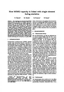
Fig. 1. (A) RT Na-S battery configuration and chemical structure of the polybenzimidazole (PBI) monomer. (b) The ionic conductivity of the PBI membrane. (c) The polysulfide diffusion test for Celgard 2500 and PBI membrane. (d) TEM image of the PBI membrane stained with periodic acid. (e, f) SEM images of (e) the top view and (f) the cross-sectional view of the PBI membrane. (g) Performance comparison of the Na/Na symmetric cells with and without the PBI membrane (8 μm).
recorded using Vertex 70 Hyperion 1000 (Bruker) with the assisstance of attenuated total reflectance (ATR) accessories. The absorption spectra were recorded from 3200 cm−1 to 400 cm−1 with a resolution of 4 cm−1. The UV-Vis spectra were collected by SEC2000 UV-visible spectrophotometer (ALS Co., Ltd.). An SCE-C thin layer quartz glass cell with an optical path length of 4.5 mm was used as the holder.
tetraglyme solution was placed inside the glass tube, whereas the opposite side of the separator was filled with a conventional tetraglyme. During the experiment, the solutions rested without movement to exclude external influence on the diffusion test of polysulfides through the separator. The resulting color change was evaluated by visual examination. The Na electrodes and discharged cathodes after cycling were washed by pure glyme and then dried in the Ar-filled glovebox before SEM observation. JSM-6700 F field emission SEM instruments were used for micrograph observation at an acceleration voltage of 5.0 kV. TEM images were taken on a high-resolution transmission electron microscopy (JEOL, 2010F TEM) using an accelerating voltage of 200 kV and the membrane samples were stained with periodic acid by placing the copper grids upon the evaporating aqueous solution containing the periodic acid to enlarge the contrast [36]. To study the surface compositions of the discharged cathode, X-ray photoelectron spectroscopy (XPS) measurements were conducted on a Physical Electronics PHI5802 instrument using an X-rays magnesium anode (monochromatic Ka X-rays at 1253.6 eV) as the source. C 1s region was used as the reference and set at 284.8 eV. Modification of a regular single cell was made for the Raman study, where the cathode end cap plate was cut with a hole and sealed with a quartz window. Raman spectra were collected using a spectrometer (Princeton Instruments, Spectrapro2500i) with a back illuminated charge-coupled detector attachment (Princeton Instruments, Spec 10) using an argon-ion laser with a wavelength of 514.5 nm and 50 mW laser power as the excitation source. To control the exposure time, the laser beam was chopped using a mechanical shutter. Raman spectra were obtained by accumulating 5 measurements, with an exposure time of 20 s. Fourier transform infrared spectroscopy (FTIR) measurements were
2.4. DFT calculation All density functional theory (DFT) based first-principles calculations were conducted adopting ABINIT code [37,38]. The exchangecorrelation functional was coped with by generalized gradient approximation (GGA) of Perdew-Burke-Ernzerhof (PBE) type and the electron-ion interactions were modeled by Projector-augmented-wave (PAW) potentials [39]. The DFT + D2 functional was used to include the physical van der Waals (vdW) interactions [40]. After the convergence tests, the energy cutoff of 24 Ha was used to ensure a satisfied convergence for wave-basis expansion. Ten Li/Na-S compounds were considered, including α-S8 (128 atoms), β-S8 (48 atoms), Li2S (12 atoms), α-Li2S2 (12 atoms), β-Li2S2 (8 atoms), Li2S4 (48 atoms), Na2S (12 atoms), α-Na2S2 (12 atoms), β-Na2S2 (8 atoms) and Na2S4 (48 atoms), and the Brillouin zones were sampled on 4 × 4 × 2, 4 × 4 × 4, 8 × 8 × 8, 8 × 8 × 10, 8 × 8 × 4, 4 × 4 × 4, 8 × 8 × 8, 8 × 8 × 10, 8 × 8 × 4 and 4 × 4 × 4 Monkhorst-Pack grids, respectively [41]. The convergence criterion of the electron self-consistent loop was 4.0 × 10⁻⁵ Ha Bohr−1 and that of structural optimization was 4 × 10⁻⁴ Ha Bohr−1. The formation energy (E f ) of the compound Lia+b Sc+d /Na a+bSc+d was calculated by: 306
Journal of Power Sources 396 (2018) 304–313
Y.X. Ren et al.
E f = ELia Sb /NaaSb + ELicSd /Na cSd −ELia+bSc+d /Naa+bSc+d
(1)
characterized with TEM and SEM. From the TEM image in Fig. 1d, for the stained PBI membrane, the spreading dark areas refer to the uniformly distributed nanochannels that are responsible for conducting Na+ ions. In addition, from the SEM images (Fig. 1e and f), the membrane surface and cross-section showed a dense morphology without any observable macropores or cracks. Polysulfides that are anchored on the polymer matrix therefore can prevent the polysulfides from entering the nanochannels, facilitating the formation of an ion-selective cathode/separator interface. Despite the investigation of ionic conductivity and selectivity, we examined the capability of PBI-based separator in suppressing dendrite. The Na/Na symmetric cell and cycled at 0.25 mA cm−2 with an areal capacity of 0.5 mAh cm−2 as shown in Fig. 1g. The PBI membranes (8 μm) were placed on the Na anode surfaces for each side with a Celgard 2500 separator inserted in between. Stable cycling without short circuit and voltage fluctuation was observed for 100 times. While for the counter part assembled with bare Na metals, cycling lasted for 77 times before dendrite occurred and the increase of overvoltage over cycling was considerable, which was attributed to the thickening of passivation layer on the Na anode and the increase of surface nonuniformity. We deduce that the achieved excellent symmetric cell performance is on one hand ascribed to the high modulus of PBI membrane, which can suppress Na anode surface deformation; on the other hand, the uniform structure of PBI allows for the even distribution of Na+ ions, facilitating smooth Na deposition [13,49–52]. The cross section and surface SEM images of the cycled Na electrodes can be found in Fig. S2, confirming the more smooth Na deposition induced by the incorporation of the PBI membrane. With the achieved results, we have confirmed the excellent ionic conductivity, ion selectivity and strong mechanical properties of the asprepared PBI membrane. The Na-S batteries were assembled for performance evaluation at different rates and voltage windows. As shown in Fig. 2a, at the voltage window of 1.8–2.8 V, where the transformation between S8 and Na2S4 occurs, the battery using a routine Celgard separator decayed dramatically showing a rather low coulombic efficiency due to the polysulfide dissolution and Na anode degradation. In sharp contrast, minor capacity fading was observed for the battery with a PBI-based separator in 160 cycles, which evidences the excellent shielding effect of PBI for the Na anode. Despite excellent stability, the EIS measurement results in Fig. S3 also show the batteries assembled with the 8 μm-PBI membrane exhibited an acceptable bulk resistance around 22 Ω. From the voltage profiles in Fig. S3, the small thickness achieved by the PBI membrane is essential for achieving low polarization. As shown in Fig. 2b and c, the battery exhibited excellent rate performance (0.1C, 0.15C, 0.2C). The discharge capacity and profile of the higher voltage plateau are generally similar with what have been observed for the Li-S battery [53]. This implies that sulfur dissolution reactions follow similar reaction pathways in both Li-S and Na-S batteries [2,54]. However, if we discharged the batteries into the voltage window representing both polysulfide dissolution and precipitation (1.2–2.8 V), the battery exhibited a rapid capacity fading (Fig. 2d). With these result, we proceed to evaluate the battery's rate capability within the voltage window of 1.2–2.8 V (Fig. 3a and b). Despite improvement of capacity retention compared to the battery with a routine separator, rather fast capacity decay was generally observed. In Fig. 3c, the Na-S battery discharge curve at 0.05C depicted a sloping higher voltage plateau and a flat lower voltage plateau, which are of almost identical capacities. Despite being discharged at a rather small current density (0.05C), the battery's capacity is generally below 837 mAh g−1 (the theoretical specific capacity based on S8/Na2S conversion is 1675 mAh g−1), indicating that Na2S might not be formed as the final discharge product. This is in sharp contrast with the Li-S battery, where the lower voltage plateau that represents the Li2S precipitation is usually 2–3 times of the higher voltage plateau as shown in Fig. S4. From the rate capability test (0.05, 0.1, 0.2, 0.3C) as shown in Fig. 3c, the lower voltage plateau that represents the formation of solid-
where ELia Sb /NaaSb , ELicSd /Na cSd and ELia+bSc+d /Naa+bSc+d are the DFT total energies of Lia Sb /Na a Sb , Li c Sd /Na cSd and Lia+b Sc+d /Na a+bSc+d , respectively. Due to the limited differences of calculated energies at 0 K and 300 K for solid-state products, it is reasonable to use the formation energies to represent for the Gibbs free energies in this question. Therefore, a negative formation energy indicates the formation of the compound is energetic favorable, and vice versa. 3. Results and discussions 3.1. Performance of batteries at different voltage windows A Na-S battery is consisting of a carbon matrix impregnated with sulfur or polysulfides as the cathode, a metallic Na anode, and a separator, all of which are immersed in the ether-based liquid electrolyte. First of all, to mitigate the capacity fading caused by polysulfide shuttle effect, we need to establish a protective shield for the Na anode in the corrosive electrolyte environment. As show in Fig. 1a, we screen out the polybenzimidazole (PBI) membrane with heterocyclic groups for this purpose because of three folds of advantages, firstly, polysulfide species can be chemically adsorbed by the rich function groups containing nitrogen (pyridine-type nitrogen (-N = ) and pyrrole-type nitrogen (-NH)) in the membrane; secondly, the pore size of PBI can be reduced to generally below several nanometer to enhance the size exclusion effect for polysulfides, while maintaining continuous porous structure to uptake liquid electrolyte; thirdly, PBI reaches a rather high tensile modulus (∼82 MPa based on our previous report) so that it can attain a small thickness with sufficient mechanical strength [42–44]. As shown in Fig. S1, the as-prepared PBI membrane was characterized by FTIR, confirming its imidazole structure containing amine and imine functional groups [43,45,46]. Ionic conductivity of PBI membrane fully immersed in the electrolyte was measured at a temperature range from 25 to 55 °C (Fig. 1b) following the reported methods [34,47]. The saturated PBI membrane (1 M NaClO4 in tetraglyme) gained an ionic conductivity around 4.27 × 10⁻⁴ S cm-1 at 25 °C, generally an order lower than the saturated Celgard 2500, but considerably higher than the non-porous sodiated Nafion (2.7 × 10⁻⁵ S cm-1 at 25 °C) [29]. In addition to the excellent Na+ conductivity, the diffusion test (Fig. 1c) provided a virtual evidence of the low polysulfide permeability of PBI membrane. For a static rest of 72 h, the transparent electrolyte side separated from Na2S8 solution with a PBI membrane (8 μm) showed minor color change owing to the two-fold blocking effects contributed by the nanosized channels together with the polysulfide binding functional groups on the PBI. On the contrary, for the control group using the Celgard separator, the color changed to green, light yellow and dark yellow because of the polysulfide diffusion driven by the concentration gradient. The polysulfide binding ability of PBI was also confirmed from the FTIR spectrum in Fig. S1. In a previous study, we have shown that the pyridine-type nitrogen (-N = ) and pyrrole-type nitrogen (-NH-) in the benzimidazole rings allow the absorption and interaction with the hard Lewis base such as KOH [36]. Sodium polysulfide species are soft Lewis bases, which, to some extent, allow them to interact with the pyridinetype and pyrrole-type nitrogen groups in the PBI membrane. In the region of 2000–1000 cm−1, the narrow peaks representing the cycle vibrations and in plane N-H (also C-H) deformation modes were decreased significantly after soaking with polysulfides. Also, the alkyl C-N stretching at 1049 cm−1 together with C]N stretching at 1440 cm−1 were decreased. Moreover, the broad intensive peak in the range of 2500–3500 cm−1, related with the hydrogen bonding of N-H, almost disappeared after soaking with polysulfides. These changes to the nitrogen relevant peaks are attributed to the formation of the coordinated N-Na-S bond [44,48]. Morphologies of the PBI membrane at different scales were further 307
Journal of Power Sources 396 (2018) 304–313
Y.X. Ren et al.
Fig. 2. (A) Cyclability of the Na-S batteries at 0.1C; (b) cyclability of the Na-S batteries at different rates and voltage windows; (c) corresponding voltage profiles (1.8–2.8 V) at different discharge rates; (d) corresponding voltage profiles at the voltage window of 1.2–2.8 V.
2.26 V, corresponding to the observed two-plateau voltage profiles. It is found that the peak current densities for the two-step reactions are very close, in adequate agreement with the charge-discharge voltage profile. From the above results, we realize that when operating the Na-S
phase discharge product declined significantly due to the enlarged overpotential at a higher discharge rate. From the cyclic voltammetry curves in Fig. 3d, there existed two separated anodic peaks at 1.87 V and 2.42 V respectively, and reversible cathodic peaks at 1.62 V and
Fig. 3. (A) Cyclability of the Na-S batteries at the voltage window of 1.2–2.8 V at 0.1C with and without the protection of PBI membrane; (b) Cyclability of the Na-S batteries at different rates; corresponding voltage profiles for the battery with protection of PBI membrane; (c) voltage profiles for the battery at different rates with the PBI membrane; (d) cyclic voltammetry curves (1.2–2.8 V) at different scan rates with the PBI membrane. The C rate is determined based on the theoretical specific capacity of sulfur (1675 mAh g−1). 308
Journal of Power Sources 396 (2018) 304–313
Y.X. Ren et al.
surface area of carbon cloth, the rate capability was inferior to the batteries with carbonized cellulose paper electrode [32,33]. But the typical two-plateau voltage profiles were still well maintained, which will allow us to study the discharge product formation processes. Fig. 4a–d show the morphologies of the discharged and charged state carbon cloths at a moderate discharge rate (0.1C). Fig. 4a shows the initial charged electrode surface covered with the amorphous precipitated sulfur [55]. After the dissolution of sulfur into polysulfides occurring at the higher voltage plateau, small burst of particles emerged at the onset of the lower voltage plateau as shown in Fig. 4b. This is shown in Fig. 4c by the presence of more uniformly distributed precipitates observed in the middle of the lower voltage plateau at around 1.6 V, smaller particles developed as progressive nucleation commences. The sizes of particles continued to grow and nearly dominated the electrode surface toward the end of discharge (1.2 V) in Fig. 4d. With these results, the surface passivation of solid discharge product occurring at the lower voltage plateau is seemingly dominated by the nucleation and growth process [56–58]. At different rates, SEM images of the discharged cathodes were presented. The cathodes discharged at a lower rate (0.05C) were found to have larger hemispherical particles (∼200 nm) as shown in Fig. 4e, while those discharged at a higher rate (0.2C) demonstrated conformal, film-like precipitates composing of uniform nanoparticles as shown in Fig. 4f. When comparing Fig. 4e and f, a higher nuclei density can be observed in the cathode discharged at a higher rate, resulting in smaller amounts of precipitates, which are in well consistence with the classical heterogeneous nucleation theory [56,58,59]. As either Na2S2 or Na2S is insulating, when the precipitates crowd together to cover the electrode surface, the overpotential will be increased significantly because of the insufficient reaction sites, especially when the areal current density is higher. While at a low areal current density (e.g. 0.05C, Fig. 4e), there is still available electrode surface indicating that active species (polysulfides) might be depleted, leading to the voltage drop [60–62]. In all cases, the sulfur utilization is generally below 50% if we assume the Na2S as the final discharge product. Therefore, we suggest Na2S2 other than Na2S is formed as the final stage of discharge, which will be testified in the following section. To determine the chemical compositions of the precipitate, X-ray photoelectron spectroscopy (XPS) was applied on the cathode sides, which were discharged to different cut-off voltages as shown in Fig. 5a. The cathode discharged to 1.7 V, which is the onset of lower voltage plateau, showed the peaks of central and terminal polysulfides, representing sulfur atoms in the center of the chain (central) and sulfur atoms at the end of the chain (terminal) [18,58]. The decrease of central polysulfide peak during discharge thus leads to the fact that polysulfide species with longer chains such as Na2S4 and Na2S5 were consumed on the lower voltage plateau. When the battery was continuously discharged, S2p peaks at 162.5 eV representing Na2S2 showed
Fig. 4. (A-d) SEM images of the electrodes taken from different stages of discharge (0.1C): (a) 2.8 V; (b) 1.7 V; (c) 1.6 V; (d) 1.2 V. The corresponding voltage profiles can be found in Fig. S5b. (e, f) discharged electrode (1.2 V) at 0.05C (e); at 0.2C (f). The sizes of discharge precipitates decrease with the increase of the discharge currents.
battery at a voltage window of 1.2–2.8 V, three major issues will arise, one is the relatively low sulfur utilization (< 50%), which might be ascribed to the intrinsic reaction mechanisms; the others are the fast capacity fading and sluggish kinetics. In order to conduct rational engineering approaches to enhance the battery performance, we firstly need to probe the intrinsic mechanism of solid discharge product formation. 3.2. Analysis of the discharge product formation process and compositions Few studies attempt to address the formation mechanism as well as chemical composition of the discharge product at the lower voltage plateau. To study what is indeed happening at the lower voltage plateau, the carbon cloth with well-defined interwoven carbon fiber was chosen, as a model system for use in the experiment and the corresponding discharge curves can be found in Fig. S5a. Due to the smaller
Fig. 5. (A, b) The corresponding XPS (a) and Raman (b) spectra of the electrodes taken from different stages of discharge (1.7 V; 1.6 V; 1.2 V). 309
Journal of Power Sources 396 (2018) 304–313
Y.X. Ren et al.
Fig. 6. Crystal structures and respective space groups for Na2S, α-Na2S2, β-Na2S2, α-Na2S4 and β-S8. Purple and yellow spheres represent sodium and sulfur atoms, respectively. (For interpretation of the references to color in this figure legend, the reader is referred to the Web version of this article.)
peaks at 205 and 443 cm−1 can be observed, related with the crystalline phase α-Na2S4, and the wide shoulder peak at around 475 cm−1 can be assigned to multiple polysulfide species such as Na2S3 and Na2S5 [64]. Over discharging, sharp peaks were observed to emerge at 449 cm−1, which indicates the formation of β-Na2S2, together with the peaks at 468 and 479 cm−1 representing α-Na2S4. To more clearly observe the insoluble discharge product, the discharged electrode was rinsed with glyme and dried in the Ar-filled glove box. We found that the final discharge product was indeed a mixture of Na2S2 with
a visible rise besides the peak for terminal polysulfides, indicating that long-chain polysulfides were reduced to form solid Na2S2 at the lower voltage plateau. There was however no peak representing Na2S, which should be located at 161.8 eV [63]. To further clarify the chemical compositions of the discharge intermediates and discharge product, Raman spectroscopy measurement was conducted as shown in Fig. 5b, which is capable of clearly separating the peaks for different species. Based on the previous Raman study conducted on the high temperature Na-S system, we found that at 1.7 V,
Fig. 7. (A-c) SEM images of the electrodes taken at the cell voltage of 1.8 V at different cycles. (d) Schematic of the discharge process with the addition of P2S5 as a complexation agent; (e) schematic of the charge process for Na-S battery with the addition of NaI as the redox mediator. 310
Journal of Power Sources 396 (2018) 304–313
Y.X. Ren et al.
Fig. 8. (A) Raman spectra of P2S5 and the discharged electrode with P2S5 additive; (b) UV-Vis spectra of NaI-P2S5 solution and the mixtures of Na2S2 and NaI-P2S5. The inset figures show the Na2S2 suspension, and the Na2S2 suspension with different amounts of NaI-P2S5. (c) Photography of glyme with the addition of triiodide (left), 0.55 mg Na2S2 in glyme with the addition of triiodide (middle), 0.37 mg Na2S2 in glyme with the addition of triiodide (right). (d) UV-Vis spectra of the triiodide solution and the mixture of triiodide and Na2S2. (e) Cyclability of Na-S batteries with different additives (0.2 M, 25 μL) at 0.2C; (f) the corresponding voltage profiles; (g) cyclic voltammetry curves of Na-S battery with the addition of NaI-P2S5. (h, i) Discharged electrode morphology for the batteries with (h) Na2S8-P2S5 additive and (i) NaI-P2S5 additive.
different phases. the main peak at 183 cm−1 should be ascribed to the formation of crystalline α-Na2S2, corresponding to a lattice mode of [SS]2-, while the shoulder at 458 cm−1 indicates the stretching mode of [S-S]2- [64]. Moreover, bands that appear at 451 cm−1 and 131 cm−1 indicate the formation of β-Na2S2. However, there are almost no peaks that can be assigned to Na2S (186, 246, 437 cm−1). In that case, it is reasoned that Na2S2 is the dominant final discharge product for Na-S batteries. With the achieved experimental results, Na2S2 other than Na2S has been identified as the final discharge product for RT Na-S battery. An interesting question thus arises: why disulfide cannot be further reduced to form sulfide in the Na-based system? To shed light on the final discharge product formation mechanism, we compare the calculated formation energy of discharge products at different discharge stages of Li-S and Na-S batteries respectively. Li2S2 has been rarely observed to exist in Li-S batteries experimentally [56,65–67]. Our calculation shows that Li2S2 is electrochemically more active than Li2S, and that the formation energy of Li2S2 is less negative than that of Li2S plus S8 by calculating the Gibbs free energy of the following reactions:
intermediate can quickly disproportionate into Li2S and long-chain polysulfides. On the contrary, we show that solid Na2S2 is thermodynamically stable in Na-S batteries. The stability of sodium disulfide, Na2S2, a compound whose presence may limit capacity, was assessed. The corresponding crystal structures and respective space groups for Na2S, α-Na2S2, β-Na2S2, α-Na2S4 and β-S8 are shown in Fig. 6 and the calculated lattice parameters are shown in Table 1. Either α-Na2S2 or βNa2S2 is predicted to be stable with respect to a two-phase mixture of Na2S and Na2S4 or Na2S and β-S8 by calculating the Gibbs free energy of the following reactions:
3Na2 S2 → 2Na2 S + Na2 S4, ΔG = 0.19 eV
Table 1 Calculated lattice parameters for β-S8, Li2S, α-Li2S2, β-Li2S2, α-Li2S4, Na2S, αNa2S2, β-Na2S2 and α-Na2S4.
3Li2 S2 → 2Li2 S + Li2 S4, ΔG = −0.0069 eV
Li2 S2 → Li2 S +
β-S8 Li2S α-Li2S2 β-Li2S2 Li2S4 Na2S α-Na2S2 β-Na2S2 Na2S4
1 S8, ΔG = −0.0862 eV 8
The corresponding crystal structures and respective space groups for Li2S, α-Li2S2, β-Li2S2, α-Li2S4 and β-S8 are shown in Fig. S6. Physically, these results suggest that solid Li2S2 is not thermodynamically stable in Li-S batteries. In real battery operation, Li2S2 when emerges as an 311
a (Å)
b (Å)
c (Å)
α (°)
β (°)
γ (°)
10.90 5.71 6.83 3.99 9.21 6.57 7.68 4.51 9.70
10.95 5.71 6.83 3.99 9.21 6.57 7.68 4.51 9.70
11.13 5.71 5.02 9.60 10.82 6.57 5.40 10.29 11.98
96.42 90 90 90 90 90 90 90 90
90 90 90 90 90 90 90 90 90
0 90 120 120 90 90 120 120 90
Journal of Power Sources 396 (2018) 304–313
Y.X. Ren et al.
Na2 S2 → Na2 S +
1 S8, ΔG = 0.25 eV 8
we can observe two absorption peaks at around 295 and 366 nm, representing I3− anion. For the sample with a lower fraction of Na2S2, the peaks of I3− anion were replaced by polysulfides including S42 − (325, 420 nm) and S62 − (350, 475 nm), while for the sample with a higher fraction of Na2S2, the polysulfides peaks were negated without the appearance of I3− peaks, indicating I3− anion is sufficiently oxidative to dissolve solid Na2S2 into long-chain polysulfides [77]. The cyclic voltammetry (CV) investigation was conducted for the Na metal battery with the addition of NaI as the electrolyte additive as shown in Fig. S7. The anodic and cathodic peaks of I3− /I− redox reaction were at 3.01 and 2.77 V respectively, showing excellent reversibility of I3− /I− redox pair. Also, from the charge-discharge test in Fig. S7, at the voltage window that triiodide/iodide redox reaction takes place, the battery can be stably cycled with minor capacity decay. The polyiodide crossover thus is supposed to be blocked by the PBI membrane as the size of polyiodide anion (0.63 nm) is similar with the size of polysulfide anions [78]. Performance comparison was conducted for the batteries added with 25 μL 0.20 M NaI-P2S5, NaI and Na2S8-P2S5 electrolyte additives respectively as shown in Fig. 8e. For the battery using 0.2 M Na2S8-P2S5 additive, Na2S8 will function as the active material, which also derives an areal capacity of 1.90 mAh cm−2. As in Fig. 8e, the highest capacity retention and coulombic efficiency was achieved for the battery with NaI-P2S5 based additive. Corresponding voltage profiles at 0.2C can be found in Fig. 8f, where discharge voltage plateaus representing triiodide reduction (2.75–2.5 V), sulfur dissolution (2.3–1.7 V) and Na2S2 precipitation (1.7–1.2 V) can be clearly observed. Over charging, I3− was generated above 3.0 V, where part of the electrochemical oxidation (charge capacity) was offset by the chemical reduction of I3− by residual Na2S2. When scanned within the voltage window of 1.2–3.4 V in the CV test in Fig. 8g, separated peaks representing the I3− reduction, sulfur dissolution and Na2S2 precipitation can be clearly observed, in well consistence with the charge/discharge curves. Compared with the batteries without NaI additive, substantial enhancement in terms of the batteries' cyclability can be observed, testifying our hypothesis that overcharging the battery into the voltage window representing I−/ I3− redox reaction can effectively decompose the residual Na2S2 and improve the cyclability. Moreover, the lower discharge voltage plateau can be found to be elevated for the battery with P2S5 additive, owing to the improved precipitation kinetics contributed by the complexation effect of P2S5. As shown in Fig. 8 (h, i), SEM images of the discharged electrodes with Na2S8-P2S5 and NaI-P2S5 show that the sizes of discharge product can be both considerably increased, explaining the improved sulfur utilization ratio. Combining these result, we well reason that NaI-P2S5 based electrolyte additive can effectively (i) improves the precipitation kinetics by forming soluble Na2S2-P2S5 complex and (ii) promotes the dissolution of Na2S2 by the chemical mediation of I−/ I3−.
Therefore, it is reasoned that Na2S2 can be stabilized as the final discharge product other than disproportionate to Na2S and higher order polysulfide species. Due to the insufficient electronic conductivity of solid Na2S2, currently it seems impossible to further sodiate Na2S2 to form Na2S with a cell voltage above 1.2 V in an electrochemical approach. Besides, without the chemical disproportion occurring in the liquid phase, the discharge product cannot grow into a large size, explaining the rather small sulfur utilization ratios even at lower rates as observed in Figs. 3 and 4 and Fig. S5 [56,68]. Moreover, the surface passivation of the electrode triggers poor reversibility due to the high chemical stability of Na2S2. As seen in Fig. 7a–c, the cycled electrodes were disassembled at 1.8 V, which is within the region of liquid-phase redox reactions. At the initial cycle, there was almost no residual of precipitates on the electrode surface at this stage. An obvious accumulation of precipitates can be observed over cycling as a portion of Na2S2 cannot be reversibly charged into polysulfides and deposited as sulfur. The electrodeposition of Na2S2 thus accounts for poor cycling stability and reversibility of the cathode. 3.3. Electrolyte additives for performance enhancement To address the sluggish precipitation kinetics of Na2S2, an idea occurring to us is to partially solubilize Na2S2 by using complexation agent as shown in Fig. 7d. We realize that even though there is minor chemical disproportion reaction, if Na2S2 can be partially formed in the liquid phase and further precipitate on the electrode surface, the discharge product can also reach a larger size and as result attain a higher sulfur utilization ratio. P2S5 is identified to form complexes with polysulfide species (including Na2S8, Na2S4 and Na2S2) and the complexes are considerably soluble [69–71]. Owing to the complexation effect, Na2S2 can alternatively be formed via either the solution-phase or liquid-phase reaction pathway (Fig. 7d). Therefore more Na2S2 can precipitate onto the electrode surface. On the other hand, to improve the surface passivation, oxidative redox couple such as I3− /I− can be employed to chemically oxidize Na2S2 as shown in Fig. 7e, while the complexation between Na2S2 and P2S5 will also facilitate Na2S2 dissolution [72–75]. With these considerations in minds, NaI-P2S5 as a bifunctional electrolyte additive is proposed. Importantly, P2S5 is insoluble in tetraglyme, but after complexing with NaI, the concentration of NaI-P2S5 (molar ratio 1:1) reaches more than 1 M, therefore it can be flexibly added in the electrolyte as an additive. Firstly, the complexation between P2S5-Na2S2 was confirmed via the Raman spectroscopy and UV-Vis. As shown in Fig. 8a, P2S5 exhibits multiple bands at 200-300 cm−1 and 700 cm−1, attributed to the P-S-P bond signal. For the discharged electrode with the addition of P2S5 additive, all P2S5 bands disappear, whereas the S-S bands from Na2S2 remain and there emerge the peak of P-S bond, which is formed from the splitting of P-S-P bond, and the peak of A1 S-S bond for P4S10+n species, which is formed from the complexation reactions [76]. Moreover, as shown in Fig. 8b, we sonicated the discharged electrodes containing Na2S2 (∼0.55 mg, 5.0 μmol) in 2 mL glyme with different amounts of NaI-P2S5 (2.5 μmol and 5.0 μmol), as shown in the inset figures of Fig. 8b. When there is 5.0 μmol NaI-P2S5, Na2S2 was generally dissolved to yield a clear solution. This message is also evidenced by the UV-Vis measurement result, in which a considerable increase of absorbance can be observed when more NaI-P2S5 is added into the Na2S2 suspension. Secondly, to provide the rationality of using triiodide/iodide redox couple, as shown in Fig. 8c, we added 2.5 μmol NaI3 into the suspension containing different amounts of Na2S2. The suspension turned into green and grey color respectively in no more than 30 s, showing the fast chemical mediation between NaI3 and Na2S2. This message can be also verified in the UV-Vis spectra in Fig. 8d, in which for the NaI3 sample
4. Conclusion In this paper, we have proposed effective methods to mitigate capacity fading of RT Na-S batteries. Polybenzimidazole (PBI)-based separator was applied, effectively shielding the Na anode surface in the corrosive electrolyte environment containing polysulfides. Combining DFT calculation and characterization techniques, we for the first time reveal that Na2S2 particles will precipitate on the electrode surface as the final discharge product. Na2S2 passivation is recognized as the predominant attributes of large polarization and capacity fading. To address the aforementioned issues, we present the use of a bifunctional NaI-P2S5 based electrolyte additive, which (i) partially solubilize Na2S2 by forming Na2S2-P2S5 complex and (ii) promotes the dissolution of Na2S2 by the chemical mediation of I−/ I3− . It is demonstrated that the battery's cyclability can be considerably improved with the cooperative effects of Na2S2-P2S5 based electrolyte additive. The efficient strategies to facilitate the reversible formation and decomposition of solid 312
Journal of Power Sources 396 (2018) 304–313
Y.X. Ren et al.
discharge product thus clearly opens a new avenue for prolonging the Na-S battery's cycle life.
[33] M. Liu, Y. Ren, H. Jiang, C. Luo, F. Kang, T. Zhao, Nanomater. Energy 40 (2017) 240–247. [34] Y. Lu, M. Tikekar, R. Mohanty, K. Hendrickson, L. Ma, L.A. Archer, Adv. Energy Mater. 5 (2015). [35] I. Bauer, S. Thieme, J. Brückner, H. Althues, S. Kaskel, J. Power Sources 251 (2014) 417–422. [36] L. Zeng, T. Zhao, L. Wei, Y. Zeng, Z. Zhang, J. Power Sources 327 (2016) 374–383. [37] X. Gonze, J.-M. Beuken, R. Caracas, F. Detraux, M. Fuchs, G.-M. Rignanese, L. Sindic, M. Verstraete, G. Zerah, F. Jollet, Comput. Mater. Sci. 25 (2002) 478–492. [38] X. Gonze, Z. für Kristallogr. - Cryst. Mater. 220 (2005) 558–562. [39] J. Perdew, K. Burke, M. Ernzerhof, Phys. Rev. Lett. 80 (1998) 891. [40] S. Grimme, J. Comput. Chem. 27 (2006) 1787–1799. [41] H.J. Monkhorst, J.D. Pack, Phys. Rev. B 13 (1976) 5188. [42] Z. Yuan, Y. Duan, H. Zhang, X. Li, H. Zhang, I. Vankelecom, Energy Environ. Sci. 9 (2016) 441–447. [43] L. Zeng, T. Zhao, L. An, G. Zhao, X. Yan, Energy Environ. Sci. 8 (2015) 2768–2774. [44] Y. Qiu, W. Li, W. Zhao, G. Li, Y. Hou, M. Liu, L. Zhou, F. Ye, H. Li, Z. Wei, Nano Letters 14 (2014) 4821–4827. [45] L. Zeng, T. Zhao, L. An, G. Zhao, X. Yan, J. Membr. Sci. 493 (2015) 340–348. [46] G. Li, C. Wang, W. Cai, Z. Lin, Z. Li, S. Zhang, NPG Asia Mater. 8 (2016) e317. [47] Y. Lu, Z. Tu, L.A. Archer, Nat. Mater. 13 (2014) 961–969. [48] M. Mamlouk, P. Ocon, K. Scott, J. Power Sources 245 (2014) 915–926. [49] M.D. Tikekar, L.A. Archer, D.L. Koch, Science advances 2 (2016) e1600320. [50] W. Luo, C.F. Lin, O. Zhao, M. Noked, Y. Zhang, G.W. Rubloff, L. Hu, Adv. Energy Mater. 7 (2017). [51] Y. Zhao, L.V. Goncharova, Q. Zhang, P. Kaghazchi, Q. Sun, A. Lushington, B. Wang, R. Li, X. Sun, Nano Letters 17 (2017) 5653–5659. [52] H. Wang, C. Wang, E. Matios, W. Li, Nano Letters 17 (2017) 6808–6815. [53] Y. Yang, G. Zheng, Y. Cui, Energy Environ. Sci. 6 (2013) 1552–1558. [54] S.-H. Yu, X. Feng, N. Zhang, J. Seok, H.c.D. Abruña, Accounts Chem. Res. 51 (2018) 273–281. [55] M. Liu, Y. Ren, D. Zhou, H. Jiang, F. Kang, T. Zhao, ACS Appl. Mater. Interfaces 9 (2017) 2526–2534. [56] Y. Ren, T. Zhao, M. Liu, P. Tan, Y. Zeng, J. Power Sources 336 (2016) 115–125. [57] B. Horstmann, T. Danner, W.G. Bessler, Energy Environ. Sci. 6 (2013) 1299–1314. [58] M. Fantauzzi, B. Elsener, D. Atzei, A. Rigoldi, A. Rossi, RSC Adv. 5 (2015) 75953–75963. [59] F.Y. Fan, M.S. Pan, K.C. Lau, R.S. Assary, W.H. Woodford, L.A. Curtiss, W.C. Carter, Y.-M. Chiang, J. Electrochem. Soc. 163 (2016) A3111–A3116. [60] T. Zhang, M. Marinescu, S. Walus, P. Kovacik, G. Offer, J. Electrochem. Soc. 165 (2018) A6001–A6004. [61] T. Zhang, M. Marinescu, L. O'Neill, M. Wild, G. Offer, Phys. Chem. Chem. Phys. 17 (2015) 22581–22586. [62] T. Zhang, M. Marinescu, S. Walus, G.J. Offer, Electrochim. Acta 219 (2016) 502–508. [63] K. Abraham, S. Chaudhri, J. Electrochem. Soc. 133 (1986) 1307–1311. [64] O. El Jaroudi, E. Picquenard, N. Gobeltz, A. Demortier, J. Corset, Inorg. Chem. 38 (1999) 2917–2923. [65] Z. Feng, C. Kim, A. Vijh, M. Armand, K.H. Bevan, K. Zaghib, J. Power Sources 272 (2014) 518–521. [66] G. Yang, S. Shi, J. Yang, Y. Ma, J. Mater. Chem. 3 (2015) 8865–8869. [67] Z. Liu, D. Hubble, P.B. Balbuena, P.P. Mukherjee, Phys. Chem. Chem. Phys. 17 (2015) 9032–9039. [68] F.Y. Fan, W.C. Carter, Y.M. Chiang, Adv. Mater. 27 (2015) 5203–5209. [69] Z. Lin, Z. Liu, W. Fu, N.J. Dudney, C. Liang, Adv. Funct. Mater. 23 (2013) 1064–1069. [70] Z. Lin, Z. Liu, W. Fu, N.J. Dudney, C. Liang, Angew. Chem. 125 (2013) 7608–7611. [71] H. Zhang, G.G. Eshetu, X. Judez, C. Li, L.M. Rodriguez-Martínez, M. Armand, Angew. Chem. Int. Ed. (2018), http://dx.doi.org/10.1002/anie.201712702. [72] Y. Ren, T. Zhao, M. Liu, Y. Zeng, H. Jiang, J. Power Sources 361 (2017) 203–210. [73] Y. Ren, M. Liu, T. Zhao, L. Zeng, M. Wu, J. Power Sources 342 (2017) 9–16. [74] Y. Ren, T. Zhao, H. Jiang, M. Wu, M. Liu, J. Power Sources 347 (2017) 136–144. [75] H.-J. Peng, J.-Q. Huang, X.-Y. Liu, X.-B. Cheng, W.-T. Xu, C.-Z. Zhao, F. Wei, Q. Zhang, J. Am. Chem. Soc. 139 (2017) 8458–8466. [76] X. Li, J. Liang, Y. Lu, Z. Hou, Q. Cheng, Y. Zhu, Y. Qian, Angew. Chem. Int. Ed. 56 (2017) 2937–2941. [77] Q. Zou, Y.-C. Lu, J. Phys. Chem. Lett. 7 (2016) 1518–1525. [78] G. Lota, K. Fic, E. Frackowiak, Electrochem. Commun. 13 (2011) 38–41.
Acknowledgment The work described in this paper was fully supported by a grant from the Research Grants Council of the Hong Kong Special Administrative Region, China (Project No.T23-601/17-R). Appendix A. Supplementary data Supplementary data related to this article can be found at http://dx. doi.org/10.1016/j.jpowsour.2018.06.056. References [1] B. Dunn, H. Kamath, J.M. Tarascon, Science 334 (2011) 928–935. [2] Y.X. Wang, B. Zhang, W. Lai, Y. Xu, S.L. Chou, H.K. Liu, S.X. Dou, Adv. Energy Mater. 24 (2017). [3] S. Chu, Y. Cui, N. Liu, Nat. Mater. 16 (2017) 16–22. [4] H. Chen, T.N. Cong, W. Yang, C. Tan, Y. Li, Y. Ding, Prog. Nat. Sci. 19 (2009) 291–312. [5] D. Larcher, J.-M. Tarascon, Nat. Chem. 7 (2015) 19–29. [6] H.-J. Peng, J.-Q. Huang, Q. Zhang, Chem. Soc. Rev. 46 (2017) 5237–5288. [7] X. Lu, B.W. Kirby, W. Xu, G. Li, J.Y. Kim, J.P. Lemmon, V.L. Sprenkle, Z. Yang, Energy Environ. Sci. 6 (2013) 299–306. [8] K.B. Hueso, M. Armand, T. Rojo, Energy Environ. Sci. 6 (2013) 734–749. [9] P. Adelhelm, P. Hartmann, C.L. Bender, M. Busche, C. Eufinger, J. Janek, Beilstein Journal of Nanotechnology 6 (2015) 1016. [10] D.-J. Lee, J.-W. Park, I. Hasa, Y.-K. Sun, B. Scrosati, J. Hassoun, J. Mater. Chem. 1 (2013) 5256–5261. [11] X. Lu, G. Li, J.Y. Kim, D. Mei, J.P. Lemmon, V.L. Sprenkle, J. Liu, Nat. Commun. 5 (2014) 4578. [12] F. Yang, S.M.A. Mousavie, T.K. Oh, T. Yang, Y. Lu, C. Farley, R.J. Bodnar, L. Niu, R. Qiao, Z. Li, Adv. Energy Mater. 11 (2018). [13] Z.W. Seh, J. Sun, Y. Sun, Y. Cui, ACS Central Science 1 (2015) 449–455. [14] Z.W. Seh, Y. Sun, Q. Zhang, Y. Cui, Chem. Soc. Rev. 45 (2016) 5605–5634. [15] Y. Liu, G. Zhou, K. Liu, Y. Cui, Accounts Chem. Res. 50 (2017) 2895–2905. [16] R. Carter, L. Oakes, A. Douglas, N. Muralidharan, A.P. Cohn, C.L. Pint, Nano Letters 17 (2017) 1863–1869. [17] Y.-X. Wang, J. Yang, W. Lai, S.-L. Chou, Q.-F. Gu, H.K. Liu, D. Zhao, S.X. Dou, J. Am. Chem. Soc. 138 (2016) 16576–16579. [18] S. Wei, S. Xu, A. Agrawral, S. Choudhury, Y. Lu, Z. Tu, L. Ma, L.A. Archer, Nat. Commun. 7 (2016). [19] Y.-M. Chen, W. Liang, S. Li, F. Zou, S.M. Bhaway, Z. Qiang, M. Gao, B.D. Vogt, Y. Zhu, J. Mater. Chem. 4 (2016) 12471–12478. [20] S. Xin, Y.X. Yin, Y.G. Guo, L.J. Wan, Adv. Mater. 26 (2014) 1261–1265. [21] T.H. Hwang, D.S. Jung, J.-S. Kim, B.G. Kim, J.W. Choi, Nano Letters 13 (2013) 4532–4538. [22] Q. Lu, X. Wang, J. Cao, C. Chen, K. Chen, Z. Zhao, Z. Niu, J. Chen, Energy Storage Materials 8 (2017) 77–84. [23] J. Wang, J. Yang, Y. Nuli, R. Holze, Electrochem. Commun. 9 (2007) 31–34. [24] S. Wenzel, H. Metelmann, C. Raiß, A.K. Dürr, J. Janek, P. Adelhelm, J. Power Sources 243 (2013) 758–765. [25] I. Kim, J.-Y. Park, C.H. Kim, J.-W. Park, J.-P. Ahn, J.-H. Ahn, K.-W. Kim, H.-J. Ahn, J. Power Sources 301 (2016) 332–337. [26] C.-W. Park, H.-S. Ryu, K.-W. Kim, J.-H. Ahn, J.-Y. Lee, H.-J. Ahn, J. Power Sources 165 (2007) 450–454. [27] J.-S. Kim, H.-J. Ahn, I.-P. Kim, K.-W. Kim, J.-H. Ahn, C.-W. Park, H.-S. Ryu, J. Solid State Electrochem. 12 (2008) 861–865. [28] D. Kumar, M. Suleman, S. Hashmi, Solid State Ionics 202 (2011) 45–53. [29] X. Yu, A. Manthiram, Adv. Energy Mater. 5 (2015). [30] X. Yu, A. Manthiram, J. Phys. Chem. C 118 (2014) 22952–22959. [31] A. Manthiram, X. Yu, Small 11 (2015) 2108–2114. [32] S.-H. Chung, A. Manthiram, Chem. Commun. 50 (2014) 4184–4187.
313