Hindawi Publishing Corporation Advances in OptoElectronics Volume 2011, Article ID 375451, 10 pages doi:10.1155/2011/375451
Research Article Electrodes for Microfluidic Integrated Optoelectronic Tweezers Kuo-Wei Huang,1 Sabbir Sattar,1 Jiang F. Zhong,2 Cheng-Hsu Chou,3 Hsiung-Kuang Tsai,3 and Pei-Yu Chiou1 1 Department
of Mechanical and Aerospace Engineering, University of California, Los Angeles, CA 90095, USA of Neurology, University of Southern California, Los Angeles, CA 90033, USA 3 Chimei-Innolux Inc., Tainan County, Southern Taiwan Science Park 744, Taiwan 2 Department
Correspondence should be addressed to Kuo-Wei Huang,
[email protected] Received 11 May 2011; Accepted 25 June 2011 Academic Editor: Aaron T. Ohta Copyright © 2011 Kuo-Wei Huang et al. This is an open access article distributed under the Creative Commons Attribution License, which permits unrestricted use, distribution, and reproduction in any medium, provided the original work is properly cited. We report on two types of electrodes that enable the integration of optoelectronic tweezers (OETs) with multilayer poly(dimethylsilane)- (PDMS-) based microfluidic devices. Both types of electrodes, Au-mesh and single-walled carbon nanotube(SWNT-) embedded PDMS thin film, are optically transparent, electrically conductive, and can be mechanically deformed and provide interfaces to form strong covalent bonding between an OET device and PDMS through standard oxygen plasma treatment. Au-mesh electrodes provide high electrical conductivity and high transparency but are lack of flexibility and allow only small deformation. On the other hand, SWNT-embedded PDMS thin film electrodes provide not only electrical conductivity but also optical transparency and can undergo large mechanical deformation repeatedly without failure. This enables, for the first time, microfluidic integrated OET with on-chip valve and pump functions, which is a critical step for OET-based platforms to conduct more complex and multistep biological and biochemical analyses.
1. Introduction Optoelectronic tweezers (OETs) demonstrated by Chiou et al. in 2005 have promised a platform for high-throughput single cell manipulation and analysis [1, 2]. The principle of manipulating microscale objects and cells on an OET platform is based on light-patterned virtual electrodes and the induced dielectrophoretic (DEP) forces [1]. Types of objects that have been manipulated using OET are versatile, including polystyrene beads [1, 2], semiconductor microdisks [3], nanowires [4], DNA molecules [5], proteins [6], sperm [7], and bacteria and mammalian cells [1, 2, 8–10]. Recent development of OET technologies also broadened the type of media in which OET can operate. Phototransistor OET enabled OET to function in regular physiological buffers with high electrical conductivity (1.5 S/m) [11]. Floating electrode OET enabled the manipulation of aqueous droplets in electrically insulating media such as oils and air [12, 13]. OET can also be integrated with digital microfluidic platform for manipulating objects carried in droplets [13, 14]. A universal platform successfully integrating OET and
optoelectrowetting (OEW) further allows optical manipulation of objects and droplets on the same featureless OET device [15]. Integration of OET with continuous phase microfluidic devices has also been realized [16, 17]. However, the integration is currently limited to simple microfluidic channels without other functional components such as valves and pumps due to the rigid and brittle property of ITO electrodes. This has limited OET’s potentials for performing complex protocols. To realize microfluidic integrated OET with more functions, here, we demonstrate two types of enabling electrodes, Au-mesh electrode and SWNT-embedded thin film electrode, that allow integrating OET with multilayer PDMS-based microfluidic devices that can provide onchip valve and pump function through deformable thin PDMS membranes. PDMS is widely used in fabricating microfluidic devices due to its elastic mechanical property, gas permeability, and simple fabrication process [18– 24]. Thousands of membrane valves and pumps can be integrated on the same chip to conduct complex and multistep biochemical analysis and synthesis protocols. OET
2
Advances in OptoElectronics
Pressure
Control channel Flow channel
AC
OET Au-mesh electrode
Light (a)
(b)
Embedded SWNT electrode (c)
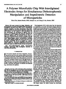
Figure 1: (a) Schematic of a microfluidic integrated OET device. (b) Devices using an Au-mesh electrode or (c) an SWNT-embedded PDMS thin film electrode as the top channel surface and the deformable check valve.
and PDMS microfluidic devices provide complementary functions. OET is a powerful tool enabling massively parallel single cell manipulation with light but not effective in manipulating fluid. On the other hand, PMDS microfluidic device is effective in controlling the delivery of fluid but ineffective in manipulating particles or cells carried by the fluid. Integration of OET with PDMS microfluidic devices promises a platform for high throughput and parallel control not only complex microfluidic circuitry but also individual cells carried by fluid. Several requirements need to be satisfied to realize such integration. First, the electrode needs to be optically transparent to allow optical imaging and diagnostics. This is important since the amorphous silicon used in OET strongly absorbs visible lights with wavelength shorter than 632 nm (red). Fluorescence excitation and observation through the amorphous silicon side is difficult and has to come from the transparent electrode side. Second, the electrode needs to be electrically conductive after deposited on the elastic PDMS surface. ITO electrodes usually crack after deposition on PDMS and cannot conduct current. Third, the PDMS device needs to provide an interface after electrode coating that can form strong bonding with the OET surface to provide good sealing and prevent liquid leakage during manipulation.
This paper shows the fabrication process, theory, OET manipulation performance, and limitations of Au-mesh and SWNT-embedded PDMS thin film electrodes.
2. Device Structures of Microfluidic Integrated OET The schematic of a microfluidic integrated OET consisting of an upper PDMS microfluidic channel and a bottom photoconductive OET surface is illustrated in Figure 1(a). Unlike a conventional OET device in which a fluid chamber is formed between an ITO electrode and a photoconductive substrate, the proposed multilayer PDMS microfluidic integrated OET can have two or more layers of channels. The bottom channel contains aqueous solutions carrying biological cells or particles and the top channel is used to control the membrane valve formed at the region where the top and bottom channels intersect. This elastic membrane works as a mechanical valve that can be controlled by pneumatic pressure to close the bottom channel and stop the fluid flow. A peristaltic pump can be achieved by actuating three valves along a channel in series.
Advances in OptoElectronics The OET surface comprises of multiple layers including an ITO, a 50-nm n+ hydrogenated amorphous silicon (aSi:H), a 1-μm undoped a-Si:H, and a 100-nm silicon dioxide. The layer of silicon dioxide is deposited for bonding with PDMS. The Au-mesh electrode (Figure 1(b)) or the SWNTembedded PDMS thin film (Figure 1(c)) is fabricated on the top surface of the bottom PDMS channel.
3
PDMS Master (a)
PDMS
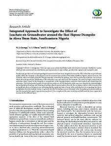
3. Au-Mesh Electrode An Au-mesh electrode is formed by two-perpendicular periodic Au/Ti stripes coated on the top surface of a PDMS channel by directional e-beam evaporation through shadow masks (Figure 1(b)). Au-mesh electrodes provide high electrical conductivity in the same order of magnitude as regular metal electrodes. The empty regions between wires control its optical transparency. Since Au covers only a small area on an Au-mesh electrode, strong bonding between PDMS and the OET can be formed through plasma treatment to provide tight sealing during fluid delivery. Figure 2 shows the fabrication process of Au-mesh electrodes. A shadow mask with an array of strips is used to create periodic metal strips through e-beam deposition on the top surface of a PDMS channel. The fabrication process of the shadow mask starts from a commercial 100 μm thick silicon wafer. A thin layer of PECVD oxide was deposited on the wafer as an etch mask for deep reactive-ion etching (DRIE). A strip pattern with a line width of 5-μm and a spacing of 50-μm was patterned on the etch mask by standard photolithography. The PDMS microfluidic channels and chambers are fabricated through standard soft lithography processes. After peeling off the PDMS structures from the mold, the periodic electrodes formed by 1 nm Ti and 100 nm Au stripes are deposited by ebeam evaporation on the PDMS surface through the shadow mask twice. In the second deposition, the shadow mask was rotated by 90 degrees. Figure 3 shows both the bright and fluorescence images of 10-μm fluorescent particles positioned 100 μm underneath an Au-mesh electrode. The particles can be clearly observed under a 10x and a 50x objective lens even for particles positioned right underneath Au wires. Since Aumesh and particles are not at the same focal plane, the Aumesh image blurs out when the imaging plane is on the OET surface. It can be expected that the larger the separation gap between OET and the electrode, the larger the blurring. Also, the higher the magnification of the objective lens is, the less is the shadowing effect. Furthermore, decreasing the width of Au wires can further reduce the shadow effect of Au-mesh. To verify the performance of OET manipulation using an Au-mesh electrode, an HeNe laser was used as the light source to induce a virtual electrode on the photoconductive surface. Nalm 6 cells were first suspended in an isotonic buffer and then flowed into the microchannels using a syringe pump. After a light beam turned on a virtual electrode, Nalm 6 cells experiencing positive DEP forces are observed to move toward the light spot as shown in Figures 4(a) and 4(b). To evaluate the DEP forces, we can translate the velocity of Nalm 6 cell into DEP force by Stock’s formula,
Metal evaporation (b)
PDMS
Covalent bonding (c)
Figure 2: (a) A master mold fabricated by SU-8 is used to define the PDMS microfluidic channels. (b) Evaporating through a shadow mask placed near the PDMS enables the fabrication of patterned Au/Ti wires on the upper surface of channels. (c) Covalent bonding is formed between the Au/Ti-mesh PDMS and the OET chip after oxygen plasma treatment on the bonding surfaces.
VDEP = (FDEP + Ffriction )/6πηR, where η is the viscosity of the media, R is the radius of the cells, and the Ffriction is the friction force between cells and the OET surfaces. Based on our experimental observation and ignoring the fiction forces, the speed was found to be 14 μm/sec giving a force of 1.3 pN. One potential drawback of Au-mesh electrode is the highly nonuniform electric field near Au wires. If cells or particles are near these wires, strong DEP forces will be induced on them. This effect turns out to be not severe when particles or cells are manipulated near the OET surface since this highly nonuniform field decreases rapidly away from the wires. This property allows Au-mesh OET to manipulate cells or particles near the photoconductive surface smoothly as a continuous electrode. This can be confirmed by the finite element method (FEM) simulation showing the electric-field distribution induced by a light beam on an Au-mesh OET device as shown in Figure 5(a). The geometry parameters used in simulation are based on real device dimensions. The width of Au-wire electrodes is 5 μm and the spacing is 50 μm. A 50-μm high chamber is filled with medium having a conductivity of 0.01 S/m. The photoconductivity of a-Si:H is assumed to follow the Gaussian distribution profile with a peak conductivity of 0.1 S/m and an FWHM spot diameter of 16.6 μm. The nonuniform electric field induced by Aumesh is limited to regions close to the top surface (shown in the 47.2 μm curve in Figure 5(b)) and quickly decays in the
4
Advances in OptoElectronics
50 μm
10x
40 μm
(a)
50x (b)
50 μm
10x (c)
40 μm 50x (d)
Figure 3: (a, b) Bright-field images and (c, d) fluorescent images of 10-μm particles underneath an Au-mesh electrode. The gap spacing between the electrode and the OET surface where the particles sit is 100 μm. The arrows point to the particles below Au wires.
100 μm
100 μm
10.5 sec (a)
(b)
100 μm
100 μm
(c)
(d)
Figure 4: (a, b) A Nalm 6 cell trapped by a light spot (the dish circle) is transported in a microfluidic channel. (c, d) Transport of a single Nalm 6 cell trapped by OET in multilayer PDMS channels. The region between two black lines is a control channel above the flowing channel where the cells are.
Advances in OptoElectronics
5
E (106 V/M) 1 0.9 0.8 0.7 0.6 0.5 0.4 0.3 0.2 0.1 0
50 μm
10 V
FWHM
= 16.6 μm
σ(R) = I(R) 0
R
(a)
Electric field strength (V/m) ×106
8 1.8 μm 6 4
7.5 μm 47.2 μm
2 0
−150
41.5 μm −100
−50
0 Position (μm)
50
100
150
(b)
Figure 5: (a) Finite element simulation of the electric field pattern in the liquid layer when a 16.6 μm wide light beam illuminates the photoconductive layer. (b) The electric field distribution at different heights above the photoconductive layer.
vertical direction. At regions near the OET surface, Au-meshinduced field gradient is negligible compared to that induced by the light beam (1.8 μm and 7.5 μm curves in Figure 5(b)). Although Au-mesh electrodes provide high electrical conductivity and high optical transparency, there are several drawbacks. First, there is a trade-off between the height of channels and the density of Au-mesh since the electrode is discrete. The nonuniform electric field induced near Au wires will affect OET manipulation when the height of channels becomes small. Increasing the channel height or reducing the spacing between Au wires can help reducing this effect. Another limitation comes from the fact that metallic films, despite more deformable than ITO, tend to peel off from PDMS surface after large deformation which also creates cracks. As a result, Au-mesh electrodes can only undergo large mechanical deformation once before failure. In Figures 4(c) and 4(d), a Nalm 6 cell was transported across a deformable PDMS membrane valve coated with Au-mesh electrode. This Au-mesh electrode failed after the PDMS membrane valve was pushed down to close the flow channel.
4. SWNT-Embedded PDMS Thin Film Electrode Motivated by the cracking issue of Au-mesh electrodes, we investigate SWNT-embedded PDMS thin film electrodes to
solve this problem. SWNTs exhibit high electrical conductivity. Films made by randomly distributed SWNT have shown potentials for flexible electronics [25]. SWNT thin films with thickness in the range of 10–100 nm can have low sheet resistance and high optical transparency as well as robust mechanical flexibility [26]. SWNT thin films have been demonstrated in devices including solar cells [27], thin film transistors [28], light emitting diodes [29], and electrowetting [30]. Recent researches suggested that the electrical stability and mechanical robustness of SWNT films could be improved by embedding SWNT thin film into polymers [31–33]. Devices made by SWNT films within polymer membranes also show promising potentials for applications on microfluidic platforms [34]. Here, we demonstrate microfluidic integrated OET using SWNT-embedded PDMS thin film electrode as shown in Figure 1(c). This electrode is continuous, optically transparent, and electrically conductive and has robust mechanical flexibility allowing large deformation without failure. The fabrication process of SWNT embedded PDMS thin film is illustrated Figure 6. The vacuum filtration method is used to get uniform SWNT thin films [35]. The suspension of SWNT is filtered through a filtration membrane to form a thin layer of SWNT network. The highly dense SWNT suspension was made by high purity (>90%) arc discharge nanotubes from Carbon Solutions, Inc. SWNTs were dissolved in 1 wt% sodium dodecyl sulfate (SDS) solution to prepare solution-based SWNT. This highly concentrated SWNT suspension was ultrasonically agitated using a probe sonicator for ∼10 minutes. To remove the carbon particles and impurities, the suspension was centrifuged at 14000 rpm for 30 minutes. A porous anodic aluminum oxide (AAO) filter (Anodisc 47, Whatman Inc.) was used in vacuum filtration. The suspension flows through the pores and leaves a thin film of an SWNT network on the surface of the AAO filter. The concentration and the volume of the flow suspension can control the density of SWNT network. A PDMS stamp is then used to transfer the SWNT thin film from the filtration membrane [36]. To fabricate the PDMS stamp, a master mold was made by using standard photolithography using a negative photoresist (SU8 2025, MicroChem corporation) on a silicon wafer. Polydimethylsiloxance (Sylgard 184, Dow Corning) with a ratio of 10 base: 1 curing agent was poured onto the master mold and cured at 65◦ C for 4 hours. A PDMS stamp with a pattern of microfluidic channels could be peeled off from the Si wafer. Before the stamp contacts the filtration membrane, it was treated by trichloro(1H, 1H, 2H, 2H-perfluorooctyl)silane (Sigam-Aldrich, Inc.), a chemical release agent that lowers the adhesive forces between the PDMS stamp and the SWNT thin film [37]. The treated PDMS stamp was then pressed in contact with the SWNT network on the AAO filter paper (Figure 6(a)). After the PDMS stamp is removed, the SWNT network is transferred onto the extruding surface of the PDMS stamp. This PDMS stamp with an SWNT thin film was then used as the mold for casting microfluidic channels. To cast the microfluidic channels, an uncured PDMS precursor at the ratio of 10 base: 1 curing agent was poured
6
Advances in OptoElectronics PDMS stamp
1:20 PDMS
SWNT on AAO (a)
(b)
1:5 PDMS
(c)
(d)
Figure 6: The fabrication process of embedding a thin layer SWNT network in a multiplayer PDMS microfluidic structure.
onto the PDMS stamp and baked in an oven. The uncured gel-like PDMS precursor infiltrates the vacant regions in the SWNT network during the curing process. The cured microfluidic channels were then be peeled off from the mold with an SWNT thin film embedded near the top surface of channels. This fabrication technique can be used to embed SWNT thin film on multilayer PDMS microfluidic devices. To achieve that, the uncured PDMS precursor at a ratio of 20 base: 1 curing agent was spin-coated on the PDMS stamp to create a thin membrane (Figure 6(b)). A top thick PDMS layer made with a ratio of 5 base: 1 curing agent is pressed to contact the thin PDMS layer. These two layers are bonded after cured (Figure 6(c)). The cured PDMS with a top control channel and a thin film SWNT embedded bottom PDMS channel can be peeled off from the first PDMS stamp as shown in Figure 6(d). This multilayer PDMS channel with an embedded SWNT thin film electrode on the top surface of bottom channels including the membrane valve locations was then bonded with an OET device through oxygen plasma treatment. In our fabrication process, the PDMS stamp is used as the mold for not only casting other microfluidic channels but also transferring an SWNT thin film to the top surface of a channel. This fabrication process is compatible with the standard soft lithography process. Figure 7(a) shows the microscopic image of the SWNT electrode embedded in a multiplayer PDMS microfluidic device. Since the SWNT electrode exists only on the top surface of the flow channels, this promises a clean surface for forming strong covalent bonding between PDMS and silicon dioxide surface of an OET device. Figure 7(b) shows the SEM image of a thin film SWNT embedded into the cured PDMS matrix. Embedded SWNT networks can provide better electrical stability and mechanical robustness.
To examine the optical transparency of SWNT electrodes, 10-μm fluorescent particles were pumped into an SWNT OET device. Figures 7(c) and 7(d) are the bright field and the fluorescence images of 10-μm fluorescent particles underneath an SWNT electrode. Three particles highlighted with arrows are located in the membrane valve location where two layers of PDMS channels cross. The relation between the measured sheet resistance and the optical transmittance at 632 nm is plotted in Figure 7(e). The optical transparency and electrical conductivity of SWNT electrodes are highly dependent on the carbon nanotube purity, tube length, and dispersion quality of the films. The transparency and the sheet resistance can be controlled by the thickness of SWNT films, which can be adjusted by the amount of SWNT in the dispersion solution. Experimental results have shown a linear relationship between sheet resistance and optical transparency. The electrodes with sheet resistance from ∼350 to ∼550 ohm per square have from 55 to 80% optical transparency measured at 632 nm. In an SWNT OET device, all the flow channels (top layer) and the control channels (bottom layer) are 300-μm wide, so the area of the valve was 300 μm × 300 μm, and the height of bottom channel was 18 μm. The valve could be pushed down to completely close the bottom flow channel by applying a pressure in the top channel. Figure 7(f) shows a series of pictures of valve function. The dye solution was pumped into an SWNT OET device by a constant pressure of 1.5 psi. The white arrows are the flow directions of dye solution. First, a pressure of 25 psi was applied into the top channel in the right-hand side, the PDMS membranes deformed, and the dye solution was stopped by the two closed valves. The dye solution moved when the two valves were open and the valve in left-hand side was close. After the dye solution was filled in the entire flow channel, the color change in the valve region indicates the closing of the valves. The electrical resistance of the SWNT electrode increased when the valve deformed. After releasing the pressure, the resistance decreased back to its original value before deformation. The SWNT-embedded PDMS thin film electrode is capable of reproducing their electrical conductivity for strain up to 40%. In the experimental setup, a DMD-based projector with its projection lens and color filters being removed is used as the light source for generating dynamic optical images. These images are projected onto the photoconductive layer by a 4x objective lens. The microfluidic integrated OET device was positioned on an inverted microscope. An ac bias of 100 kHz, 10 Vpp is applied to the SWNT electrode in the PDMS channel and the ITO electrode on the OET device. Figures 8(a) and 8(b) are the snapshots of images showing a 10-μm particle being transported across a deformable PDMS membrane valve by dynamic light images. The performance of OET manipulation using an SWNT embedded PDMS thin film electrode has been compared with a regular ITO electrode. An HeNe laser which was set on an up-right microscope was used as the light source to trigger virtual electrodes. Therefore, the incident laser light is from the bottom side of the photoconductive layers, avoiding the optical transmittance difference between two top electrodes (ITO and SWNT). 10-μm particles were
Advances in OptoElectronics
7
1 mm 10.0 kV ×100 k
(a)
500 nm (b)
150 μm (d)
(c) 600
Sheet resistance (ohm)
550 500 450 400 350 300 50
60 70 80 Transmittance at 632 nm (%)
90
(e)
(f)
Figure 7: (a) A microscopic image of SWNT-embedded valves and channels in multilayer PDMS microfluidic structures. The channel is bonded on an OET chip. (b) A SEM image of SWNT network embedded in the surface of PDMS. (c, d) Bright field and fluorescence image of 10 μm fluorescence particles underneath an SWNT electrode. (e) Measured sheet resistance of SWNT-embedded PDMS electrodes and its relation with optical transmittance at 632 nm. (f) A series of pictures showing the valve function by deforming the SWNT membrane electrode. The white arrows are the flow directions of the dye solution in the flow channels. The black arrows show the pressure sources to deform the membranes. The dye solution can be stopped by pushing down the membrane. The scale bars are 600 μm.
8
Advances in OptoElectronics
150 μm (a)
(b)
Average velocity (μm/sec)
12 10 8 6 4 2 0
6
8
7
9
10
Voltage (Vpp) SWNT ITO (c)
Figure 8: (a, b) Transport of a 10-μm particle by light across a membrane valve on an OET-integrated multilayer PDMS device. The scale bars are 150 μm. (c) Comparison of particle moving speed in OET using ITO electrode and SWNT-embedded PDMS electrode. The light intensity is 1.5 W/cm2 and the applied frequency is 100 kHz.
diluted in KCl solution of 0.07 mS/cm and injected into a liquid chamber which was formed by an ITO electrode or an SWNT electrode. The tests were under the application of an ac bias with different voltage but in the same liquid chamber and at the same frequency, 100 kHz. Figure 8(c) shows the average velocities of 10-μm particles under different voltages. The SWNT electrodes behave like regular ITO electrodes under these operation conditions. The particle transport speed using the SWNT electrode is similar to a regular ITO electrode. We can estimate that the DEP forces in both electrodes are almost the same.
5. Conclusion We have successfully demonstrated two types of enabling electrodes that permit OET devices to integrate with multilayer PDMS microfluidic devices with on-chip valve and pump functions for conducting multistep and complex biological diagnostic protocols. Au-mesh electrodes provide high electrical conductivity and high optical transparency but lack of robust mechanical flexibility. Au-mesh electrode cracks after large mechanical deformation. SWNTembedded PDMS thin film electrode solves this cracking
issue and also provides required electrical conductivity and optical transparency for effective OET operation in a microfluidic integrated OET device. Sheet resistance of 350∼ 550 ohm/square can be obtained with optical transparency of 55% to 80%. The SWNT-embedded PDMS thin film electrode has robust mechanical flexibility, can tolerate a maximum strain of 40%, and can be used as a membrane valve to completely close a flow channel repeatedly without losing its electrical conductivity property.
Acknowledgments The authors thank Professor Chih-Ming Ho’s group for supporting experimental facilities, Professor Hsian-Rong Tseng’s group for their helps with fabrication of PDMS devices, and Dr. Liangbing Hu and Professor George Gruner for their discussion about SWNT thin films. The appreciation is extended to the staff at UCLA Nanoelectronics Research Facility for their helps with microfabrication. This work has been funded by NSF CAREER AWARD ECCS 0747950 and DBI 0852701.
Advances in OptoElectronics
References [1] P. Y. Chiou, A. T. Ohta, and M. C. Wu, “Massively parallel manipulation of single cells and microparticles using optical images,” Nature, vol. 436, no. 7049, pp. 370–372, 2005. [2] A. T. Ohta, P. Y. Chiou, T. H. Han et al., “Dynamic cell and microparticle control via optoelectronic tweezers,” Journal of Microelectromechanical Systems, vol. 16, no. 3, pp. 491–499, 2007. [3] M. C. Tien, A. T. Ohta, K. Yu, S. L. Neale, and M. C. Wu, “Heterogeneous integration of InGaAsP microdisk laser on a silicon platform using optofluidic assembly,” Applied Physics A, vol. 95, no. 4, pp. 967–972, 2009. [4] A. Jamshidi, P. J. Pauzauskie, P. J. Schuck et al., “Dynamic manipulation and separation of individual semiconducting and metallic nanowires,” Nature Photonics, vol. 2, no. 2, pp. 86–89, 2008. [5] P. Y. Chiou, A. T. Ohta, A. Jamshidi, H. Y. Hsu, and M. C. Wu, “Light-actuated AC electroosmosis for nanoparticle manipulation,” Journal of Microelectromechanical Systems, vol. 17, no. 3, pp. 525–531, 2008. [6] H. Hwang and J. K. Park, “Measurement of molecular diffusion based on optoelectrofluidic fluorescence microscopy,” Analytical Chemistry, vol. 81, no. 21, pp. 9163–9167, 2009. [7] A. T. Ohta, M. Garcia, J. K. Valley et al., “Motile and nonmotile sperm diagnostic manipulation using optoelectronic tweezers,” Lab on a Chip, vol. 10, no. 23, pp. 3213–3217, 2010. [8] A. T. Ohta, P. Y. Chiou, H. L. Phan et al., “Optically controlled cell discrimination and trapping using optoelectronic tweezers,” IEEE Journal on Selected Topics in Quantum Electronics, vol. 13, no. 2, pp. 235–242, 2007. [9] J. K. Valley, S. Neale, H. Y. Hsu, A. T. Ohta, A. Jamshidi, and M. C. Wu, “Parallel single-cell light-induced electroporation and dielectrophoretic manipulation,” Lab on a Chip, vol. 9, no. 12, pp. 1714–1720, 2009. [10] W. Choi, S. W. Nam, H. Hwang, S. Park, and J. K. Park, “Programmable manipulation of motile cells in optoelectronic tweezers using a grayscale image,” Applied Physics Letters, vol. 93, no. 14, Article ID 143901, 2008. [11] H. Y. Hsu, A. T. Ohta, P. Y. Chiou, A. Jamshidi, S. L. Neale, and M. C. Wu, “Phototransistor-based optoelectronic tweezers for dynamic cell manipulation in cell culture media,” Lab on a Chip, vol. 10, no. 2, pp. 165–172, 2010. [12] S. Park, C. Pan, T. H. Wu et al., “Floating electrode optoelectronic tweezers: light-driven dielectrophoretic droplet manipulation in electrically insulating oil medium,” Applied Physics Letters, vol. 92, no. 15, Article ID 151101, 2008. [13] S. Y. Park, S. Kalim, C. Callahan, M. A. Teitell, and E. P. Y. Chiou, “A light-induced dielectrophoretic droplet manipulation platform,” Lab on a Chip, vol. 9, no. 22, pp. 3228–3235, 2009. [14] G. J. Shah, A. T. Ohta, E. P. Y. Chiou, M. C. Wu, and C. J. C. J. Kim, “EWOD-driven droplet microfluidic device integrated with optoelectronic tweezers as an automated platform for cellular isolation and analysis,” Lab on a Chip, vol. 9, no. 12, pp. 1732–1739, 2009. [15] J. K. Valley, S. Ningpei, A. Jamshidi, H.-Y. Hsu, and M. C. Wu, “A unified platform for optoelectrowetting and optoelectronic tweezers,” Lab on a Chip, vol. 11, no. 7, pp. 1292–1297, 2011. [16] Y. H. Lin and G. B. Lee, “Optically induced flow cytometry for continuous microparticle counting and sorting,” Biosensors and Bioelectronics, vol. 24, no. 4, pp. 572–578, 2008.
9 [17] D. H. Lee, H. Hwang, and J. K. Park, “Generation and manipulation of droplets in an optoelectrofluidic device integrated with microfluidic channels,” Applied Physics Letters, vol. 95, no. 16, Article ID 164102, 2009. [18] G. M. Whitesides, “The origins and the future of microfluidics,” Nature, vol. 442, no. 7101, pp. 368–373, 2006. [19] J. C. McDonald, D. C. Duffy, J. R. Anderson et al., “Fabrication of microfluidic systems in poly(dimethylsiloxane),” Electrophoresis, vol. 21, no. 1, pp. 27–40, 2000. [20] M. A. Unger, H. P. Chou, T. Thorsen, A. Scherer, and S. R. Quake, “Monolithic microfabricated valves and pumps by multilayer soft lithography,” Science, vol. 288, no. 5463, pp. 113–116, 2000. [21] T. Thorsen, S. J. Maerkl, and S. R. Quake, “Microfluidic largescale integration,” Science, vol. 298, no. 5593, pp. 580–584, 2002. [22] D. J. Laser and J. G. Santiago, “A review of micropumps,” Journal of Micromechanics and Microengineering, vol. 14, no. 6, pp. R35–R64, 2004. [23] N. T. Nguyen and Z. Wu, “Micromixers—a review,” Journal of Micromechanics and Microengineering, vol. 15, no. 2, pp. R1– R16, 2005. [24] J. W. Hong and S. R. Quake, “Integrated nanoliter systems,” Nature Biotechnology, vol. 21, no. 10, pp. 1179–1183, 2003. [25] Q. Cao and J. A. Rogers, “Ultrathin films of single-walled carbon nanotubes for electronics and sensors: a review of fundamental and applied aspects,” Advanced Materials, vol. 21, no. 1, pp. 29–53, 2009. [26] L. Hu, D. S. Hecht, and G. Gr¨uner, “Carbon nanotube thin films: fabrication, properties, and applications,” Chemical Reviews, vol. 110, no. 10, pp. 5790–5844, 2010. [27] M. W. Rowell, M. A. Topinka, M. D. McGehee et al., “Organic solar cells with carbon nanotube network electrodes,” Applied Physics Letters, vol. 88, no. 23, Article ID 233506, 2006. [28] Q. Cao, S. H. Hur, Z. T. Zhu et al., “Highly bendable, transparent thin-film transistors that use carbon-nanotube-based conductors and semiconductors with elastomeric dielectrics,” Advanced Materials, vol. 18, no. 3, pp. 304–309, 2006. [29] D. Zhang, K. Ryu, X. Liu et al., “Transparent, conductive, and flexible carbon nanotube films and their application in organic light-emitting diodes,” Nano Letters, vol. 6, no. 9, pp. 1880– 1886, 2006. [30] L. Hu, G. Gruner, J. Gong, C. J. Kim, and B. Hornbostel, “Electrowetting devices with transparent single-walled carbon nanotube electrodes,” Applied Physics Letters, vol. 90, no. 9, Article ID 093124, 2007. [31] L. Hu, D. S. Hecht, and G. Gr¨uner, “A method of fabricating highly transparent and conductive interpenetrated carbon nanotube-parylene networks,” Nanotechnology, vol. 20, no. 46, Article ID 465304, 5 pages, 2009. [32] E. Lahiff, C. Y. Ryu, S. Curran, A. I. Minett, W. J. Blau, and P. M. Ajayan, “Selective positioning and density control of nanotubes within a polymer thin film,” Nano Letters, vol. 3, no. 10, pp. 1333–1337, 2003. [33] K. Lee, S. S. Lee, J. A. Lee, K. C. Lee, and S. Ji, “Carbon nanotube film piezoresistors embedded in polymer membranes,” Applied Physics Letters, vol. 96, no. 1, Article ID 013511, 2010. [34] H. Cao, Z. Gan, Q. Lv et al., “Single-walled carbon nanotube network/poly composite thin film for flow sensor,” Microsystem Technologies, vol. 16, no. 6, pp. 955–959, 2010. [35] Z. Wu, Z. Chen, X. Du et al., “Transparent, conductive carbon nanotube films,” Science, vol. 305, no. 5688, pp. 1273–1276, 2004.
10 [36] Y. Zhou, L. Hu, and G. Gr¨uner, “A method of printing carbon nanotube thin films,” Applied Physics Letters, vol. 88, no. 12, Article ID 123109, 3 pages, 2006. [37] M. Zhang, J. Wu, L. Wang, K. Xiao, and W. Wen, “A simple method for fabricating multi-layer PDMS structures for 3D microfluidic chips,” Lab on a Chip, vol. 10, no. 9, pp. 1199– 1203, 2010.
Advances in OptoElectronics
International Journal of
Rotating Machinery
The Scientific World Journal Hindawi Publishing Corporation http://www.hindawi.com
Volume 2014
Engineering Journal of
Hindawi Publishing Corporation http://www.hindawi.com
Volume 2014
Hindawi Publishing Corporation http://www.hindawi.com
Volume 2014
Advances in
Mechanical Engineering
Journal of
Sensors Hindawi Publishing Corporation http://www.hindawi.com
Volume 2014
International Journal of
Distributed Sensor Networks Hindawi Publishing Corporation http://www.hindawi.com
Hindawi Publishing Corporation http://www.hindawi.com
Volume 2014
Advances in
Civil Engineering Hindawi Publishing Corporation http://www.hindawi.com
Volume 2014
Volume 2014
Submit your manuscripts at http://www.hindawi.com
Advances in OptoElectronics
Journal of
Robotics Hindawi Publishing Corporation http://www.hindawi.com
Hindawi Publishing Corporation http://www.hindawi.com
Volume 2014
Volume 2014
VLSI Design
Modelling & Simulation in Engineering
International Journal of
Navigation and Observation
International Journal of
Chemical Engineering Hindawi Publishing Corporation http://www.hindawi.com
Volume 2014
Hindawi Publishing Corporation http://www.hindawi.com
Hindawi Publishing Corporation http://www.hindawi.com
Volume 2014
Hindawi Publishing Corporation http://www.hindawi.com
Advances in
Acoustics and Vibration Volume 2014
Hindawi Publishing Corporation http://www.hindawi.com
Volume 2014
Volume 2014
Journal of
Control Science and Engineering
Active and Passive Electronic Components Hindawi Publishing Corporation http://www.hindawi.com
Volume 2014
International Journal of
Journal of
Antennas and Propagation Hindawi Publishing Corporation http://www.hindawi.com
Shock and Vibration Volume 2014
Hindawi Publishing Corporation http://www.hindawi.com
Volume 2014
Hindawi Publishing Corporation http://www.hindawi.com
Volume 2014
Electrical and Computer Engineering Hindawi Publishing Corporation http://www.hindawi.com
Volume 2014