To appear in IIE Transactions.
Research in Object-Oriented Manufacturing Simulations: An Assessment of the State of the Art* S. Narayanan1, D. A. Bodner2, U. Sreekanth3, T. Govindaraj2, L. F. McGinnis2, and C. M. Mitchell2 1. Department of Biomedical and Human Factors Engineering, College of Engineering and Computer Science, Wright State University, Dayton, OH 45435 USA 2. School of Industrial and Systems Engineering, Georgia Institute of Technology, Atlanta, GA 30332-0205 USA 3. Web Products Division, Silicon Graphics Computer Systems, Mountain View, CA 94043 USA
Abstract Object-oriented programming (OOP) has been revolutionizing software development and maintenance. When applied to simulation of manufacturing systems, OOP also provides an opportunity for developing new ways of thinking and modeling. In this paper, we identify existing large-scale, persistent OOP-based research efforts focusing on manufacturing system simulation, and present an integrating framework for discussing the associated modeling abstractions, implementation strategies, common themes, and distinctive features. The goal is to identify the fundamental research and application issues, assess the current state of the art, and identify key research needs.
*
. Please direct all correspondence to Dr. Leon F. McGinnis, Director, Computer Integrated Manufacturing Systems, School of Industrial & Systems Engineering, Georgia Institute of Technology, Atlanta, GA 303320205. Phone: +1 404 894 5562. Fax: +1 404 894 2301. Email:
[email protected].
1. Introduction Advanced manufacturing systems are capital-intensive due to hardware and software requirements. As a result, it is essential that they achieve high levels of flexibility and productivity compared to traditional manufacturing systems. Modeling and analysis to gain a better understanding of the system complexities and to predict system performance are critical in the system design stage, and often valuable for system management. Modern manufacturing systems tend to be tightly coupled. They are characterized by a high degree of automation, low levels of work-in-process inventory, and various forms of supervisory control. These systems are difficult to analyze using purely analytic models, such as queueing theory or queueing networks [14]. Simulation is an indispensable tool for their design and operational performance analyses. The rapid growth of the simulation software market provides evidence for the popularity of simulation. Not only are there a number of general purpose simulation languages such as SIMAN (ARENA), SLAM II (AWESIM), MODSIM and GPSS, but also specialized languages and simulators for manufacturing, such as AutoMod, ProModel, and Factor [28]. Simulation languages provide ready-made modeling constructs, and are generally compiled into a standard programming language, such as Fortran or C. One fundamental problem in applying simulation languages is that of modeling, i.e., using the abstractions of the language to describe the system being analyzed. Recent interest in object-oriented programming (OOP) applied to manufacturing simulation has led to a significant body of related research in the modeling of manufacturing systems ([2], [20], [36], [40], [58], [64]). There is significant compatibility between the OOP paradigm and the discrete-event world-view formalism ([13], [45], [62]). To be truly useful, though, research in OOP applied to simulation modeling must have an impact on one or more of the key aspects of simulation modeling and analysis: abstraction, implementation, application, verification, and validation. One reason for the tremendous appeal of OOP is a major change in abstraction, moving from the traditional “seize-hold-release” paradigm of simulation languages to a more “natural mapping” paradigm. This is made possible by the object construct, which allows a one-to-one mapping between objects in the manufacturing system being modeled (process equipment, material handling equipment, programmable controllers, cell controllers, etc.) and their abstractions in the simulation model ([22], [40]). OOP also has a major effect on implementation through its facilitation of modular design and software reusability ([19], [36], [40], [63]). When exploited, OOP features such as encapsulation, inheritance, and polymorphism facilitate code reuse and programming efficiency [26]. (Refer to Appendix A for a glossary of commonly used terms in object-oriented programming.) For building simulation models, the idea is to design and implement reusable classes and store them in a software library, thus facilitating rapid model development. The concept of a reusable class library therefore aids in application of the modeling architecture to specific scenarios. Extending this idea, one can build a model base, or collection of models, that can be used to facilitate model development further. The OOP paradigm has other potential benefits in verification. The
2
feature of encapsulation in OOP enforces structured code development. Together with modular systems design principles, OOP also offers potential advantages in the incremental development and verification of simulations of large-scale systems [63]. In addition, OOP provides a natural environment for graphical user interface development [58]. Graphical animation of simulation output has been found to be useful in model verification and analysis. Finally, natural mappings offer the modeler fundamental abstractions that correspond closely to the manufacturing world being simulated, thus facilitating bottom-up validation of models. Thus, backed by a design purpose, OOP applied to manufacturing simulation modeling and analysis can be potentially very beneficial. The natural appeal of OOP in manufacturing simulation has motivated many researchers, whose work is published in a broad range of journals. The objective of this paper is not to provide a comprehensive review of this rapidly expanding literature. Instead, this paper focuses on a subset of the literature representing large-scale, persistent efforts that have addressed fundamental architectural issues, i.e., how we should think about manufacturing in order to create simulation models, and computing tools to implement that way of thinking. The motivation is to make this research available to the widest possible audience, and to identify the current directions of research and future research opportunities. To this end, we focus on the following research efforts: • BLOCS/M - University of California, Berkeley ([1], [2], [3], [19], [20], [33]). BLOCS/M is the first manufacturing-specific object-oriented simulation architecture, applied primarily to problems in semiconductor fabrication. • DEVS - University of Arizona ([49], [61], [63], [64]). DEVS is both a methodology and a software implementation, with applications to autonomous systems modeling. • Laval - Laval University ([17], [30], [34], [38]). The Laval architecture focuses on several phases of factory design, including simulation. • OOSIM - Georgia Institute of Technology ([10], [22], [40], [41], [42], [43], [53]). The OOSIM effort focuses on automated operation as well as human supervisory control issues in integrated, discrete-part manufacturing systems. • OSU-CIM - Oklahoma State University ([5], [7], [8], [18], [36], [37], [47], [48]). OSU-CIM focuses on modeling and simulation of discrete parts manufacturing systems, with emphasis on the separation of the modeling process from problem solving activities. • SmartSim/SmarterSim - University of Michigan, Dearborn ([54], [55], [57], [58]). SmartSim focuses on simulation program generation for manufacturing. Each of these research efforts passes the test for persistence, having published related papers over an extended period. Each effort has proposed an architecture and an associated implementation strategy, and conducted several case studies. Each has its own, sometimes implicit, objectives, world-view, and approach. Thus, it is not a
3
simple matter for the newcomer to integrate, comprehend, or build upon the base of existing research results from these efforts. Note that there are a number of examples of work that uses generic OOP classes directly to develop specific simulation models. Such efforts are not included here, because we also focus on the architecture development phase. Likewise, there have been OOP-based modeling efforts where the focus is other than simulation, e.g., manufacturing control ([44], [52]), or flexible manufacturing systems [56]. These also are not included. Our paper does not imply that all significant research work in this area has only come out of the six major schools of thought reviewed in this paper. Several interesting results emerging from the other research programs are overviewed in Appendix B. A common framework is needed for discussing OOP-based approaches to manufacturing system simulation. It is especially important to understand the process of abstraction, that ultimately defines the classes employed in the object-oriented simulation method. The framework developed in the next section explicitly addresses the processes for both development and application of a modeling architecture for object-oriented simulation. The remainder of the paper is organized as follows. Section 3 considers the specific key issues of research objectives, domain analysis, and software design principles. Section 4 describes the modeling architectures themselves. Section 5 discusses the simulation implementations. Finally, Section 6 provides an assessment of future directions in the field.
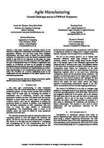
2. A framework for research in object-oriented manufacturing simulations Each of the six research programs reviewed here has exhibited two distinct but related phases of activity as illustrated in Figure 1. Development of the architecture results in a set of classes, methods, tools, etc., that are used to create and analyze specific simulation models. Implementation and application is the process of using the class hierarchies and methods to create specific simulation models in order to demonstrate and evaluate the classes and methods. We will refer to those two phases of activity, respectively, as development and testing. For the research programs reviewed here, development and testing have been iterative. The view of development shown in Figure 1 begins with a domain, employs a process of analysis and modeling, and results in the architecture, a generic manufacturing system modeling formalism. Testing is simply the traditional simulation process -- abstraction (in this case, using the architecture), implementation in software, verification, execution, validation of the model against the system being modeled, design of experiments, and output analysis [29]. Testing the architecture often reveals opportunities to improve the architecture, hence the iteration between testing and development. Each of the six research efforts has developed its own architecture. All have tested their architectures and found them workable. Our objective is not to evaluate the architectures, per se, but to examine the process of developing an architecture. Each of the architectures is both a conceptual, or modeling, framework, and the basis for software development. The architectures are influenced, either explicitly or implicitly, by two distinct concerns: (1)
4
the content and structure of the domain of intended application; and (2) software engineering. Together, these two concerns guide the decisions leading to specific classes, class hierarchies, methods, and model implementation strategies. To understand the current state of object-oriented manufacturing simulation, it is essential to understand the modeling abstractions that have been proposed (the essence of the architectures), and the underlying domain analysis and software engineering principles. Domain analysis is defined as “... the process of identifying and organizing knowledge about some class of problems -- the problem domain -- to support the description and solution to those problems” [4]. Domain analysis, in this context, describes how researchers view or choose to talk about the manufacturing domain. The domain analysis may be either explicit or implicit. If it is implicit, it must be inferred from the resulting modeling abstractions. Significant differences between the six architectures reflect, in part, the absence of a standard reference model for manufacturing systems [9], i.e., a generally accepted domain analysis. Software engineering principles also influence the modeling abstractions. Clearly OOP principles play a major role, e.g., through encapsulation, sub-classing, etc. In fact, it is not a straightforward matter to develop class hierarchy for a well-understood system. For example, Meyer [35] points out that in the design of the Eiffel libraries, the extraction of commonalities to effectively utilize inheritance was not easy and not accomplished in one attempt. An a posteriori realization that some classes can be reconstructed to support better reusability plays a major role in development and testing. Many researchers involved in OOP and manufacturing simulations point out that the development starts with the class definition of top-level classes, proceeds through class definitions at the lower-level and moves back upward as lower-level abstractions are tailored to applications. This idea is well-captured in the fountain model of object-oriented systems life cycle [24]. In reviewing the six architectures, we have attempted to identify the key elements of the domain analysis and the key software design principles that are reflected in each architecture. We have also identified the research objectives and rationale, as expressed by the researchers, their implementation platforms, and the kinds of applications involved, because it is likely that these aspects have significant influence on the architectures. Each architecture is summarized in terms of its classes, class hierarchy, and the process for using the architecture to create a simulation model.
3. Objectives, domain analysis, and software design principles Table 1 summarizes the research objectives and rationale for using OOP. Clearly, each of the six research efforts has a distinct motivation. Aside from the generic attributes of OOP (reusability, ease of maintenance, etc.), the most common rationale is the possibility of natural mappings (e.g., abstractions which correspond closely to the entities found in a manufacturing system). Using OOP, it is possible to develop modeling abstractions that have a natural mapping to manufacturing entities such as machines, parts, transporters, computerized controllers, etc.. With
5
a successful implementation there is potential to facilitate model development and validation. SmartSim/SmarterSim, OSU-CIM, OOSIM, and Laval focus on developing abstractions that have a natural correspondence to real-world manufacturing entities. SmartSim research has demonstrated that using their abstractions within a graphical specification environment has resulted in more rapid model building. OSU-CIM research is involved in developing abstractions that make a distinction between physical objects, decision-making objects, and information objects. The motivation for the separation between physical, information, and control objects is primarily to provide a highly reusable modeling environment and secondarily to provide a more natural modeling environment. Not all of the research groups have described an explicit domain analysis, so it must be inferred in several cases. In these cases, we present the fundamental abstractions from the architecture. The assumption here is that the abstractions reflect the way in which the researchers view manufacturing systems. Similarly, in some cases the key software design principles must be inferred from the structure of the architectures and the process for constructing simulation programs. One software design principle of many research efforts is to achieve reuse through a software library. Typically, for a novel scenario, appropriate existing abstractions are drawn out from the library, and are applied to model the desired system. When the existing abstractions are not sufficient, they are adapted by creating a subclass of an existing abstraction, or by creating a new class that is not a derivative of any existing class. The new class itself is then stored in the library. In addition to achieving reuse through libraries, the key software design considerations discussed here include (1) using OOP features such as inheritance and encapsulation, and (2) developing generic constructs for specifying model structure and behavior. The remainder of this section discusses the domain analysis and software design of each of the research efforts. • BLOCS/M: BLOCS/M has four fundamental abstractions to represent objects in manufacturing: lots, resources, tasks, and routes. Lots comprising the work-in-process (WIP) inventory move from one workstation (a resource) to another, where operations are performed. An operation sequence specifies the route for a lot. There are two types of events that occur in a manufacturing system. One type is exogenous (e.g., failure) while the other is associated with resource allocation decisions. Resource allocation decisions are associated with the beginning of the task. For the duration of the task, the allocated resources are busy and cannot be assigned to another task. Events that mark the beginning and end of a task generally change the state of several resources simultaneously. For software design, BLOCS/M focuses on the development of a library of reusable classes. The classes are designed according to the one function / one object principle, in which each object does only one thing. This makes for simple classes. BLOCS/M uses sub-classing to develop objects with new behavior from pre-existing classes (e.g., to create a machine object that can fail from a machine class that does not exhibit this behavior). • DEVS: The fundamental abstractions in DEVS are atomic models and components built from the atomic models. The DEVS research does not develop abstractions that directly map into the physical manufacturing
6
system in terms of machines, controllers, etc. Rather, systems are viewed generically as a set of independently verifiable subsystems. These subsystems are modeled by modules that can be readily connected to establish the entire model. The model itself can then be developed hierarchically. Key software design principles therefore include modularity through encapsulation and use of inheritance. The DEVS formalism provides a construct for model structure by developing formal semantics for interaction between coupled entities and providing for data encapsulation [64]. • Laval: The Laval effort views a manufacturing system as an organism composed of intelligent entities called agents and non-intelligent entities called objects. Agents have reasoning, motivation, perception and communication capabilities and perform a wide variety of roles in the manufacturing system. The nonintelligent entities in manufacturing systems are grouped in organizations such as departments and cells. Agents often interact with one another in making decisions. The focus in the Laval research is on developing adequate representations for encapsulating decisions made in manufacturing. Agents perform tasks such as scheduling, managing vehicles, creating orders, and guiding robot actions. In terms of software design, the Laval architecture achieves reuse through the generic structure of agents and organizations. It exploits inheritance through a class hierarchy. The construct provided by the organism representation allows for a generic representation of the structure of manufacturing systems. • OOSIM: OOSIM classes are based on an explicit domain analysis of discrete-part manufacturing systems. This domain analysis supports several conceptual views of manufacturing [42]. These views include the process/location view, logistics/location view, process/control view, and logistics/control view. This domain analysis results in the following fundamental abstractions: material, locations, controllers, and process plans. Locations can either process material (e.g., processing location), store material (e.g., storage location), or move material (e.g., transporter location). A process plan dictates what processing operations must be performed in transforming material from the raw material stage to a finished product. Locations are organized into controlled domains (e.g., shop level, cell level, and workstation level). Each controlled domain has a controller. Controllers are event-driven entities that respond to state changes. A controller can communicate with entities in its domain (e.g., send command information to a process location or receive status information from a location), and also to other controllers. All the entities that interact with a controller are its clients. Each controller has models of the clients with which it interacts. Database objects encapsulate the information in a manufacturing system. For software design, OOSIM develops a class library to achieve reuse and also develops a class hierarchy. Additionally, the architecture uses the construct of control domains to model the structure of a manufacturing system. Location and controller objects are designed so that their structure provides a script-based representation of behavior. This contrasts with the
7
sub-classing approach taken by BLOCS/M and OSU-CIM in modeling similar objects with different behaviors. • OSU-CIM: In OSU-CIM, entities in a manufacturing system have physical properties, control properties, and information properties. Several key abstractions result from this perspective. In particular, physical objects include workstations, material handlers, and queues; control objects include queue controller, assembly queue controller, and workcenter controller; and information objects include customer order, bill of materials, and operation. Like BLOCS/M, the OSU-CIM architecture emphasizes the software design principle of one function / one object to achieve reusability. OSU-CIM does not exploit inheritance in the form of a hierarchy of classes, but rather exploits sub-classing to develop objects with different behaviors (similar to BLOCS/M). OSU-CIM seeks to develop a model base, which is a collection of models from which the modeler may develop models of specific scenarios. • SmartSim/SmarterSim: SmartSim/SmarterSim researchers have applied the DEVS formalism to develop representations that correspond closely to manufacturing entities. The SmartSim/SmarterSim research builds on the fundamental abstraction of subsystem in DEVS to provide additional abstractions for parts, workstations, conveyors, and routers. Parts move from one workstation to another through conveyors (or other material handlers). A router is used to represent control decisions. Like DEVS, the entities can be built hierarchically. In addition to the software design principles from DEVS, SmartSim/SmarterSim adds graphical representations of manufacturing entities as an important factor of the software design process.
4. Architectures Table 2 summarizes the classes and class hierarchies for each of the six architectures. The class names shown refer to abstractions for various manufacturing system entities. Clearly, we are giving only the most superficial description of each architecture -- the interested reader should obtain additional details from the citations provided. In using an architecture to implement a simulation model, there are two fundamental issues: how to couple the class instances, and how to represent specific behavior. Each is addressed in some detail below.
4.1 Coupling mechanisms The coupling mechanisms in the modeling architecture dictate how to establish the interrelationships between manufacturing entities. The coupling mechanisms are the relational attributes of entities in the manufacturing simulation model [39]. Data encapsulation in OOP facilitates the representation of indicative attributes (i.e., attributes pertaining to a single object). However, OOP does not readily facilitate the representation of relational attributes. Zeigler [64] describes this problem comprehensively in contrasting modular, hierarchical models
8
and the OOP paradigm. He points out that in conventional OOP, connections between objects and their communication protocols are rigidly specified at the design stage. This limits the development of a generic structure for coupling objects in an integrated manufacturing system. Research efforts in object-oriented manufacturing simulations have dealt with the problem of coupling either by using custom-built interfaces or by providing a programmable standard interface. In the custom-built interfaces, entities are coupled through application-specific code for each application. In the programmable-standard interfaces, there is a generic structure for assembling objects for a specific system simulation. In both BLOCS/M and OSU-CIM, the goal is to make the objects simple so that they do not impose restrictions on how they are put together for a specific simulation. Objects of various classes in the library are declared, and their relationships are custom-built for each application. A fundamental requirement of this approach is to design the abstractions so they can be assembled readily in constructing a simulation. In DEVS, SmartSim/SmarterSim, Laval, and OOSIM, coupling is achieved through programmable-standard interfaces. In the DEVS formalism, all interactions between subsystems occur through input ports and output ports. Interactions occur through message passing, and there is a significant amount of information encapsulated in the modules. SmartSim/SmarterSim has similar abstractions to facilitate hierarchical modular modeling. In the Laval architecture, the interrelationship between agents is programmed through hypergraphs. The hypergraphs are specialized abstractions to represent interactions. In OOSIM, interactions between one controlled domain and another occur through shared locations. A shared location is an abstraction that provides for the representation of physical transfer of material from one controlled domain to another. The client models in OOSIM controllers support information transfer between individual entities in a manufacturing system. The exact number and types of clients are programmed for a specific simulation.
4.2 Behavioral specification The behavior of an entity over time during a simulation is dictated by the behavioral specification of the modeling abstractions and is realized through events. In BLOCS/M and OSU-CIM, events are represented procedurally as methods of classes. For example, consider a workstation which upon receiving a part, begins with a set-up operation, then starts processing, and then completes an operation after processing time units. Further, assume that it does not fail during any of the operations. For purposes of simulation, there is a class defined for this type of workstation that has methods for set-up, start, and complete events, thus encapsulating the behavior. Multiple workstations with the same behavior but different data (e.g., for processing time) can be readily simulated by creating instances of the class. The class library typically contains several classes to represent various workstations exhibiting different behaviors. Thus, in the BLOCS/M library, there are classes for setUpWorkstation, unreliableWorkstation, etc.
9
In OOSIM, events are also associated with classes (e.g., a device failure is associated with a device class). However, a declarative representation of events is used to specify the behavior of an entity. Event sequences that characterize the behavior of an entity are packaged in templates called scripts that are based on event graphs [51]. The scripts are initialized when the simulation model is generated for a specific application. Different behaviors of workstations, for example, can be readily specified using the same underlying structure of a workstation [42]. In DEVS, internal and external transitions, output and time-advance mechanisms are specified for all the subsystems in the model. These specifications characterize the behavior of simulated entities. In SmartSim/SmarterSim, the behavior of an entity is specified in terms of elemental operations (e.g., activities). An operation has a set of rules and tallies associated with its completion. Additionally, operations are linked via a network which represents the occurrence of a sequence of operations [54]. The Laval approach uses methods of organism objects to model the behavior of the entities that the organisms represent. These methods correspond to events. New behavior specifications for an organism are derived by adding a new organism or editing an existing one. Agents represent the decision-making behavior of the system, and the relationships between agents are specified during the generation of the simulation model. Decision-making is a key aspect of object-oriented simulation. The abstractions in traditional simulation languages are powerful because they capture many fundamental aspects of systems being modeled, but they are very limited for representing decision making ([46], [50]). OOP is influenced by research in artificial intelligence (in addition to extensions in modular programming), where the concentration is on knowledge representation [63]. Thus, many research efforts in object-oriented manufacturing simulations focus on developing constructs for modeling decision making and control in manufacturing. The DEVS constructs, based on system-theoretic concepts, combine the representation of both structural and behavioral knowledge in simulation modeling. The constructs are generic and are not oriented specifically towards manufacturing. BLOCS/M has abstractions called task objects that essentially seize and release resource objects during simulation. Several subclasses of task including moveTask, setUpTask, and repairTask seize and release resource objects corresponding to those operations. BLOCS/M attempts to decentralize decision making by providing a combination of “dInfo” (decision information) objects and using methods of the “Queue” class. A dInfo object accompanies each resource object. Information about the resource pertaining to decision making is encapsulated in the dInfo objects. The methods of dInfo objects are invoked by Queue objects during decision making. Thus, in BLOCS/M, the data relevant to decision making are structured separately. However, there do not appear to be explicit representations to encapsulate the decision making process itself. The Laval effort has developed abstractions called agents for implementing manufacturing decision making in simulations. Agents can use rule-based logic or can execute external programs (e.g., solve a linear program). An
10
agent stores knowledge in frames and makes goal-satisfying decisions. The agent abstraction in Laval is quite flexible in part because it lacks a detailed structure. Subsequent research concentrates on implementing a more structured representation of agents [38]. Hypergraphs are used to establish associations and interrelationships between agent entities. The OSU-CIM research effort separates physical, information, and controller objects. The controller objects embody complex logic in decision making. In the machine abstraction, the controller is essentially the linkage between input and output queues and the processor. The queue and processor embody limited behaviors associated with holding and processing material. Queues essentially hold and release parts for the processor via a controller. The decision making processes can be organized hierarchically at various control levels: system level, shop level, workcenter level, and device level. There does not appear to be an explicit internal architecture for control, although the conceptual development and prototype implementation of the base model concept has focused on the modeling of control at various levels. The researchers state that “... these control levels can sometimes be modeled as expert systems” [36]. The OSU-CIM architecture also attempts to provide a common framework for integrating Petri nets and queueing network models with simulations. The OOSIM research effort also distinguishes physical elements from the decision making entities in the factory. In addition, information about a manufacturing system (e.g., a process plan) is captured in a set of database classes. Controllers in OOSIM are structured using the client-server paradigm and each controller responds to its clients using logic specified by the modeler through scripts. Abstractions called controllerScripts specify the logic executed by a controller in response to client events. Input to scripts are similar to software recipes input to computerized controllers on the manufacturing shop floor. Controller scripts are plan schemas that describe how a desired goal can be achieved at an abstract level, and result in a specific sequence of actions when invoked. Scripts in the OOSIM architecture are used to explicitly represent decisions made in manufacturing systems (for example, routing, dispatching, and part introduction).
5. Simulation implementation Table 3 summarizes the implementation platform and applications for each of the six architectures, and Table 4 summarizes the process for implementing a specific simulation model. While not discussed here, each architecture incorporates the necessary simulation infrastructure, such as event lists, clocks, random number generators, etc. These elements of the architecture may be influenced by the OOP platform; however, they are not considered key elements for understanding the state of object-oriented manufacturing simulation. The remainder of this section briefly discusses two trends observed in the implementation of the six simulation architectures: simulation program generators to build models and distributed concurrent processing to aid in program execution.
11
5.1 Simulation program generators Most research efforts typically develop a front end to their architectures following the development of the modeling architecture. The goal of front-end architectures is to facilitate the use of the modeling architecture. Rozenblit et al. [49] and the SmartSim/SmarterSim researchers [55] have developed object-oriented simulation program generators (SPG) for the DEVS framework. Adiga et al. [3] have developed a knowledge-based system to support prototyping simulations using the modeling abstractions in the BLOCS/M library. Research in OOSIM has also focused on the development of an interface for configuring manufacturing simulations using the OOSIM architecture [53]. Recent work in OSU-CIM has been on the development of the model base concept that supports multi-use, multi-tool modeling environments [18]. The fundamental goal in all these efforts is to make the architecture more useful to actual users, who may be novice programmers interested in simulation modeling of manufacturing systems. A major driving force of all the research in front-end architecture is the need for rapid prototyping tools in manufacturing systems analysis and modeling. Although the researchers share the same fundamental goal, the nature of support at the front-end appears to be highly influenced by the modeling abstractions, the underlying view of manufacturing, and implicit domain analysis of the simulation model development process. There is a need for a common framework to synthesize results of the research efforts in designing front-ends to object-oriented modeling architectures. In our view, efforts towards an explicit analysis of the simulation model development process are necessary to evolve the framework.
5.2 Distributed concurrent processing With the modularity of object-oriented programs, some research efforts are motivated to exploit concurrency and parallel simulations. The goal is to use parallel architectures to deal with the computational complexity of discrete-event simulations. In OOSIM, although the controller processing is distributed and the simulation and interface to simulation are separate processes, the modeling abstractions have not been tested in parallel architectures. The DEVS formalism exploits “external-event parallelism” for use in “hierarchical simulation” [63]. Bhuskute and Mize of the OSU-CIM research group [8] have investigated the performance of a parallel implementation of a simulation of a hypothetical manufacturing system. They take advantage of deterministic routing structures in the system and achieve better performance in the simulation execution results using a parallel architecture. As manufacturing systems become more distributed in nature, object-oriented programming offers the potential to model the interactions of heterogeneous entities as they cooperate to coordinate activities within the system. The notion of an agent as in the Laval architecture offers a flexible way to begin modeling such heterogeneous entities. Further research is needed in this area to develop approaches to modeling distributed and parallel processing.
12
6. An assessment of where the field is going One can view the “doing” of manufacturing simulation as a collection of activities, each falling somewhere on the continuum shown in Figure 2. At the extreme left is comprehending the problem instance. Moving to the right, one finds creating a verbal/numeric description of the problem instance, creating a formal problem statement, creating a specific simulation model, creating a special purpose simulation code, and, finally, creating a simulation code using a general purpose programming language. As one moves from left to right, one moves from an intuitive comprehension of the problem into a computational framework. This continuum provides a framework for assessing object-oriented manufacturing simulation research. For example, the emergence of object technology as a general purpose programming paradigm is, by itself, an impetus for experimentation with the new technology in the context of manufacturing simulation. The six research programs reviewed here, however, represent more than simply experimenting with a new technology. One theme that emerges from an examination of these six programs is the confluence of dissatisfaction with existing simulation tools and the emergence of the new object technology. For example, the BLOCS/M effort was motivated, at least in part, by the difficulty of software maintenance -- OOP held out the promise of making this task easier. The Laval effort sought to model “intelligence” in manufacturing systems -- Smalltalk [21] provided a convenient pathway to the artificial intelligence/expert systems community. The OOSIM effort worked toward realtime, interactive simulations -- it seemed as easy to use C++ as to build onto existing simulation languages. The key observation is that existing tools did not provide a convenient means to satisfy a growing list of modeling and analysis needs. Rather than modifying existing tools, all of the research groups discussed in this paper developed new tools based on the emerging object-oriented programming technology. There is little doubt that object technology, in this sense, will have a major impact on simulation tools. Already, there are commercially available simulation languages that are “object-oriented,” e.g., MODSIM [12]. However, these only represent object-based implementations of the existing simulation paradigm. They address those activities at the right side of Figure 2. While important in leading to improved simulation tools, this aspect of the research is not, in our view, the most significant. Representing complex behavior in a simulation model always has been a challenge. Quite often the user of a simulation language feels compelled to resort to the underlying general purpose language to represent complex decision logic. Sometimes, the use of abstractions such as semaphores, delays, queues, etc., to represent complex logic leads to simulation programs that are not obvious, and are therefore difficult to validate and maintain. Given a single complex scenario, different (competent, even expert) simulation analysts are likely to produce quite different simulation programs, using the same language. In a sense, there is a large “distance” between the abstractions used by manufacturing engineers to describe their problems and the abstractions used by simulation experts to code their models using conventional simulation
13
languages. A theme that is very prominent in the research reviewed here is this distance, i.e., developing abstractions that are appropriate both for a formal problem statement and as the basis for simulation modeling tools. This represents the focus on the left side of Figure 2. It is this intense focus on formal modeling abstractions for manufacturing systems that is, perhaps, the most significant aspect of the research on object-oriented manufacturing simulation. The natural conclusion for this aspect of the research might be the development of a generic “reference model,” or canonical format for describing a manufacturing system. Clearly, such a reference model is not yet in sight, and object-oriented modeling is not the only conceivable approach. In fact, “simulators,” such as AutoMod, ProModel and Factor [28], which embody a limited form of reference model, have become increasingly popular. One conclusion about the research reviewed here is unavoidable: it is enormously expensive in terms of human resources to develop an architecture for object-oriented manufacturing simulation. Yet, development, testing, and iterating are essential for further progress toward a manufacturing reference model. Perhaps the greatest needs in this research community today are for: (1) both tools and methods for domain analysis in order to refine the architectures with a minimum of iteration, and (2) a forum where the evolution of manufacturing system reference models can be debated and encouraged. A final theme that seems clear in the research reviewed here is a search for better ways to represent complex behavior. Traditionally, complex behavior in a simulation model has resulted in ad hoc native language code in the corresponding simulation program. This allows the simulation analyst flexibility, but with no modeling or programming discipline. Each of the six research efforts presents a different solution to the problem of representing complex behavior, with different forms and degrees of discipline. One of the benefits of object technology is that it encourages the encapsulation of the behavior-generating decisions, and a clear, careful definition of the interfaces to the rest of the system. In summary, it does not appear that research on object-oriented manufacturing simulation is causing a revolution in the field. Rather, this research is more likely to initiate a period of substantial evolution, and we can look for these distinct kinds of change: (1) the commercialization of object-based simulation languages and to some extent object-oriented architectures (e.g., BPG BLOCS [33]), (2) improved methods and tools for representing behavior, and (3) the emergence of formal reference models for manufacturing systems.
14
7. Summary In this paper, we have identified existing large-scale, persistent, OOP-based research efforts that focus on manufacturing simulation. Our purpose has been to identify the current and future directions of research in this field. We have proposed a framework that shows the activities associated with developing object-oriented architectures for manufacturing simulation. The framework shows the importance of (i) domain analysis as a process of developing abstractions to represent manufacturing systems and (ii) software design in the implementation of those abstractions to realize the benefits of OOP. Taken together, domain analysis and the natural mappings of OOP are powerful tools in the development of new abstractions for manufacturing systems. An architecture with a graphical front end to abstractions derived from domain analysis and a software design harnessing the natural mapping capability of objectoriented programming can enable a modeler to concentrate on the manufacturing problem and not on the programming details. OOP provides many useful features for simulation modeling including natural mappings, modular design, and software reusability. However, robust abstractions for manufacturing systems modeling do not happen by accident. In our view, thorough domain analysis and appropriate software design principles play a significant role in the process of developing a modeling architecture. Additionally, the development and use of an architecture for manufacturing simulation modeling using OOP form an iterative process. We hope that our framework motivates more researchers to explicitly outline their sometimes implicit domain analysis and software design. OOP offers benefits in the behavioral representation of manufacturing entities through the encapsulation in an object of data that can represent the attributes of a manufacturing entity and methods that can represent its behavior. The classes resulting from implementation can be stored in a class library or potentially in a model base. These lead to benefits in model development and bottom-up validation. However, coupling mechanisms are a potential weak point in OOP representations. Because it takes time to develop robust abstractions, object-oriented manufacturing simulation is a technology with which one must be careful. Due to the overhead involved, this methodology may not be particularly worthwhile for small isolated efforts. Existing simulation languages may be sufficient for simple, one-time modeling type applications in manufacturing. However, research in graphical front ends should bring more of the power of OOP within the reach of users. By discussing the similarities and differences in the persistent research efforts, and by identifying common themes and principles, this survey begins to lay the foundation for developing a unifying framework and common formalism for modeling and simulation of manufacturing systems. Additionally, the importance, the conceptual difficulties and the implications of representing control and decision-making are clearly spelled out via comparison of the different research efforts. This survey also provides a feel for the types of manufacturing systems that are amenable to modeling and simulation via OOP. We hope that this assessment of the current state of the research in
15
object-oriented manufacturing simulations proves useful in raising key questions and motivating future research in the areas of domain analysis, software design, and the impact of OOP on the different areas of manufacturing simulation.
Acknowledgments This work was supported in part by the National Science Foundation under grant DDM-9102370 and by the Material Handling Research Center at the Georgia Institute of Technology. We thank Bob Leavitt at IBM T. J. Watson Research Center for his encouragement and support of our work. We also appreciate the comments of the reviewers of an earlier draft of this article; their comments have strengthened the content of the paper.
References [1]
Adiga, S. (1988) Software modelling of manufacturing systems: a case for an object-oriented programming approach. Annals of Operations Research, 17, 363 - 378.
[2]
Adiga, S. and Glassey, C. R. (1991) Object-oriented simulation to support research in manufacturing systems. International Journal of Production Research, 29 (12), 2529-2542.
[3]
Adiga, S., Petrakian, R. G. and Shabe, P. M. (1992) A knowledge-based support system for prototyping simulations with a reusable software library. Information and Decision Technologies, 18 (3), 185-194.
[4]
Arango, G. and Prieto-Diaz, R. (1991) Domain analysis: concepts and research directions, in Domain Analysis and Software Systems Modeling, Prieto-Diaz, R. and Arango, G. (Eds.), IEEE Computer Press, Washington, DC, 9-32.
[5]
Basnet, C. B., Farrington, P. A., Pratt, D. B., Kamath, M., Karacal, S. C. and Beaumariage, T. G. (1990) Experiences in developing an object-oriented modeling environment for manufacturing systems, in Proceedings of the 1990 Winter Simulation Conference, Balci, O., Sadowski, R. P. and Nance, R. E. (Eds.), IEEE, Piscataway, NJ, 477-481.
[6]
Basnet, C. and Mize, J. H. (1995) A rule-based, object-oriented framework for operating flexible manufacturing systems. International Journal of Production Research, 33 (5), 1417-1431.
[7]
Bhuskute, H. C., Duse, M. N., Gharpure, J. T., Kamath, M. and Mize, J. H. (1992) Design and implementation of a highly reusable modeling and simulation framework for discrete part manufacturing systems, in Proceedings of the 1992 Winter Simulation Conference, Swain, J. J., Goldsman, D., Crain, R. C. and Wilson, J. R. (Eds.), IEEE, Piscataway, NJ, 680-687.
[8]
Bhuskute, H. C. and Mize, J. H. (1993) Parallel discrete event simulation of manufacturing systems, in Proceedings of the 2nd Industrial Engineering Conference, Mitta, D. A., Burke, L. I., English, J. R., Gallimore, J., Klutke, G. and Tonkay, G. L. (Eds.), IIE, Norcross, GA, 705-709.
[9]
Biemans, F. P. M. (1989) A reference model for manufacturing planning and control. Technical Report, Phillips Laboratories, Braircliff Manor, New York.
16
[10]
Bodner, D. A., Dilley-Schneider, S. J., Narayanan, S., Sreekanth, U., McGinnis, L. F., Mitchell, C. M. and Govindaraj, T. (1993) Object-oriented modeling and simulation of automated control in manufacturing, in Proceedings of the 1993 IEEE International Conference on Robotics and Automation, IEEE Computer Society Press, Washington, DC, 3, 83-88.
[11]
Booch, G. (1991) Object-Oriented Design with Applications, The Benjamin/Cummings Publishing Company, Inc., Redwood City, CA.
[12]
Bryan, Jr., O. F. (1989) MODSIM II - an object-oriented simulation language for sequential and parallel processors, in Proceedings of the 1989 Winter Simulation Conference, MacNair, E. A., Musselman, K. J. and Heidelberger, P. (Eds.), IEEE, Piscataway, NJ, 172-177.
[13]
Burns, J. R. and Morgeson, J. D. (1988) An object-oriented world-view for intelligent discrete, next-event simulation. Management Science, 34 (12), 1425-1440.
[14]
Buzacott, J. and Shanthikumar, J. (1985) On approximating queueing models of dynamic job shops. Management Science, 31, 870-887.
[15]
De Meter, E. C. and Deisenroth, M. P. (1991) GIBSS: a model specification framework for multi-stage, manufacturing system design. Simulation, 56 (6), 413-420.
[16]
Drolet, J. R. (1992) A generic object-oriented simulator for material handling systems: conception and analysis,” in Proceedings of the International Material Handling Research Consortium, pp. 79-91.
[17]
Drolet, J. R., Moodie, C. L. and Montreuil, B. (1991) Object-oriented simulation with Smalltalk-80: a case study, in Proceedings of the 1991 Winter Simulation Conference, Nelson, B. L., Kelton, W. D and Clark, G. M. (Eds.), IEEE, Piscataway, NJ, 312-321.
[18]
Duse, M., Gharpure, J., Bhuskute, H., Kamath, M., Pratt, D. and Mize, J. (1993) Tool-independent model representation, in Proceedings of the 2nd Industrial Engineering Research Conference, Mitta, D. A., Burke, L. I., English, J. R., Gallimore, J., Klutke, G. and Tonkay, G. L. (Eds.), IIE, Norcross, GA, 700-704.
[19]
Glassey, C. R. and Adiga, S. (1989) Conceptual design of a software object library for the simulation of semiconductor manufacturing systems. Journal of Object-Oriented Programming, 2, Nov./Dec., 39-43.
[20]
Glassey, C. R. and Adiga, S. (1990) Berkeley Library of Objects for Control and Simulation of Manufacturing (BLOCS/M), in Applications of Object-Oriented Programming, Pinson, L. J. and Wiener, R. S. (Eds.), Addison Wesley, Reading, MA, 1-27.
[21]
Goldberg, A. and Robson, D. (1989) Smalltalk-80: The Language, Addison-Wesley, Reading, MA.
[22]
Govindaraj, T., McGinnis, L. F., Mitchell, C. M. and Platzman, L. K. (1990) Manufacturing simulation using objects, in Proceedings of the 1990 Summer Computer Simulation Conference, Svrcek, B. and McRae, J. (Eds.), Society for Computer Simulation, San Diego, CA, 219-224.
[23]
Guo, D., Norrie, D. H. and Fauvel, O. R. (1990) Object-oriented flexible manufacturing system simulation, in Proceedings of the 1990 Summer Simulation Conference, Svrcek, B. and McRae, J. (Eds.), Society for Computer Simulation, San Diego, CA, 225-230.
[24]
Henderson-Sellers, B. and Edwards, J. M. (1990) The object-oriented systems life cycle. Communications of the ACM, 33 (9), 142-159.
17
[25]
Johnson, M. E. (1990). An intelligent simulation environment for manufacturing systems analysis, in Proceedings of the 1990 International Industrial Engineering Conference, IIE, Norcross, GA, 351-360.
[26]
Johnson, R. E. and Foote, B. (1988) Designing reusable classes. Journal of Object-Oriented Programming, 1, June/July, 22-35.
[27]
Korson, T. and McGregor, J. D. (1990) Understanding object-oriented: a unifying paradigm. Communications of the ACM, 33 (9), 40-60.
[28]
Law, A. M. (1990) Simulation software for manufacturing applications. Industrial Engineering, 22 (7), 18-20.
[29]
Law A. M. and Kelton, W. D. (1991) Simulation Modeling and Analysis, McGraw-Hill, New York.
[30]
Lefrancois, P. and Montreuil, B. (1994) An object-oriented knowledge representation for intelligent control of manufacturing workstations. IIE Transactions, 26 (1), 11-26.
[31]
Levas, A. and Jayaraman, R. (1989) WADE: An object-oriented environment for modeling and simulation of workcell applications. IEEE Transactions on Robotics and Automation, 5 (3), 324-335.
[32]
Lomow, G. and Baezner, D. (1989) A tutorial introduction to object-oriented simulation and Sim++, in Proceedings of the 1989 Winter Simulation Conference, MacNair, E. A., Musselman, K. J. and Heidelberger, P. (Eds.), IEEE, Piscataway, NJ, 140-146.
[33]
Lozinski, C. (1992) The design and implementation of BPG BLOCS, in Proceedings of the International Conference on Object-Oriented Manufacturing Systems, University of Calgary, Calgary, Alberta, 271-76.
[34]
Mayrand, E., Lefrancois, P. and Montreuil, B. (1993) An agent-oriented simulation model of manufacturing activities. Integrated Computer Integrated Engineering, 1 (2), 137-146.
[35]
Meyer, B. (1990) Tools for the new culture: lessons from the design of the Eiffel libraries. Communications of the ACM, 33 (9), 69-88.
[36]
Mize, J. H., Bhuskute, H. C., Pratt, D. B. and Kamath, M. (1992) Modeling of integrated manufacturing systems using an object-oriented approach. IIE Transactions, 24 (3), 14-26.
[37]
Mize, J. H. and Pratt, D. B. (1991) A comprehensive object-oriented modeling environment for manufacturing systems, in Proceedings of the Joint International Conference on Factory Automation and Information Management, Ahmad, M. M. and Sullivan, W. G. (Eds.), CRC Press, Boca Raton, FL, 250-257.
[38]
Montreuil, B., Lefrancois, P. and Harvey, S. (1994) An organism-oriented modeling approach to support the analysis and design of intelligent manufacturing systems. Journal of Intelligent Manufacturing, 5 (2), 121142.
[39]
Nance, R. E. (1981) The time and state relationships in simulation modeling. in Communications of the ACM, 24 (4), 173-179.
[40]
Narayanan, S., Bodner, D. A., Mitchell, C. M., McGinnis, L. F., Govindaraj, T. and Platzman, L. K. (1992) Object-oriented simulation to support modeling and control of automated manufacturing systems, in Proceedings of the 1992 Western Multiconference, Society for Computer Simulation, San Diego, CA, 55-63.
18
[41]
Narayanan, S., Bodner, D. A., Sreekanth, U., Dilley, S. J., Govindaraj, T., McGinnis, L. F. and Mitchell, C. M. (1992) Object-oriented simulation to support operator decision making in semiconductor manufacturing, in Proceedings of the 1992 IEEE International Conference on Systems, Man, and Cybernetics, IEEE, Piscataway, NJ, 1510-1515.
[42]
Narayanan, S., Bodner, D. A., Sreekanth, U., Govindaraj, T., McGinnis, L. F. and Mitchell, C. M. (1994) Modeling control decisions in manufacturing systems simulation using objects, in Proceedings of the 1994 IEEE International Conference on Systems, Man, and Cybernetics, IEEE, Piscataway, NJ, 1392-1397.
[43]
Narayanan. S., Mitchell, C. M., Govindaraj, T. and McGinnis, L. F. (1993) Supporting the analysis of automation and operator problemsolving in discrete manufacturing systems, in Proceedings of the 1993 IEEE International Conference on Systems, Man, and Cybernetics, IEEE Piscataway, NJ, 3, 382-387.
[44]
Naylor, A. W. and Volz, R. A. (1987) Design of integrated manufacturing system control software. IEEE Transactions on Systems, Man, and Cybernetics, 17 (6), 881-897.
[45]
O’Keefe, R. (1986) Simulation and expert systems - a taxonomy and some examples. Simulation, 46 (1), 1016.
[46]
Platzman, L. K. and Gershwin, S. B. (1986) Simulating computer integrated manufacturing systems: how to model what traditional methods force you to ignore, in Proceedings of the 1986 IEEE International Conference on Systems, Man, and Cybernetics, IEEE Piscataway, NJ, 1007-1008.
[47]
Pratt, D. B., Farrington, P. A., Basnet, C. B., Bhuskute, H. C., Kamath, M. and Mize, J. H. (1994) The separation of physical, information, and control elements for facilitating reusability in simulation modeling. International Journal in Computer Simulation, 4 (3), 327-342.
[48]
Pratt, D. B., Mize, J. H. and Kamath, M. (1993) A case for bottom-up modeling, in Proceedings of the 2nd Industrial Engineering Research Conference, Mitta, D. A., L. I. Burke, L. I., English, J. R., Gallimore, J., Klutke, G. and Tonkay, G. L. (Eds.), IIE, Norcross, GA, 430-434.
[49]
Rozenblit, J. W., Kim, T. G. and Zeigler, B. P. (1988) Towards an implementation of a knowledge-based system design and simulation environment, in Proceedings of the 1988 Winter Simulation Conference, Abrams, M. A., Haigh, P. L. and Comfort, J. C. (Eds.), IEEE, Piscataway, NJ, 226-231.
[50]
Ruiz-Mier, S. and Talavage, J. (1989) A hybrid paradigm for modeling of complex systems, in Artificial Intelligence, Simulation, and Modelling, Widman, L. A., Loparo, K. A. and Nielsen, N. (Eds.), Wiley InterScience, New York, 381-395.
[51]
Schruben, L. (1983) Simulation modeling with event graphs. Communications of the ACM, 26 (11), 957-963.
[52]
Smith, J. S. and Joshi, S. B. (1992) Reusable software concepts applied to the development of FMS control software. International Journal of Computer Integrated Manufacturing, 5 (3), 182-196.
[53]
Sreekanth, U., Narayanan, S., Bodner, D. A., Govindaraj, T., Mitchell, C. M. and McGinnis, L. F. (1993) A specification environment for configuring a discrete-part manufacturing system simulation infrastructure, in Proceedings of the 1993 IEEE International Conference on Systems, Man, and Cybernetics, IEEE, Piscataway, NJ, 1, 349-354.
19
[54]
Thomasma, T., Mao, Y. and Ulgen, O. M. (1990) Defining behavior in a hierarchical object oriented simulation program generator, in Proceedings of the 1990 Summer Computer Simulation Conference, Svrcek, B. and McRae, J. (Eds.), Society for Computer Simulation, San Diego, CA, 266-271.
[55]
Thomasma, T. and Ulgen, O. M. (1988) Hierarchical, modular simulation modeling in icon-based simulation program generators for manufacturing, in Proceedings of the 1988 Winter Simulation Conference, Abrams, M. A., Haigh, P. L. and Comfort, J. C. (Eds.), IEEE, Piscataway, NJ, 254-262.
[56]
Tirpak, T. M., Daniel, S. M., LaLonde, J. D. and Davis, W. J. (1992) A note on a fractal architecture for modelling and controlling flexible manufacturing systems. IEEE Transactions on Systems, Man, and Cybernetics, 22 (3), 564-567.
[57]
Ulgen, O.M., and Thomasma, T. (1990) SmartSim: an object oriented simulation program generator for manufacturing systems. International Journal of Production Research, 28 (9), 1713-1730.
[58]
Ulgen, O. M., Thomasma, T. and Mao, Y. (1989) Object oriented toolkits for simulation program generators, in Proceedings of the 1989 Winter Simulation Conference, MacNair, E. A., Musselman, K. J. and Heidelberger, P. (Eds.), IEEE, Piscataway, NJ, 593-600.
[59]
Vanderbrook, R. and Sauter, J. A. (1991) A case study: integrated methods and tools for optimization, in CIM Implementation Guide, Third Edition, Bertain, L. (Ed.), Society of Manufacturing Engineers, Dearborn MI, 105-121.
[60]
Wu, B. (1995) Object-oriented systems analysis and definition of manufacturing operations. International Journal of Production Research, 33 (4), 955-974.
[61]
Zeigler, B. P. (1987) Hierarchical, modular discrete-event modelling in an object-oriented environment. Simulation, 49 (5), 219-230.
[62]
Zeigler, B. P. (1987) Knowledge representation from Newton to Minsky and beyond. Applied Artificial Intelligence, 1, 87-107.
[63]
Zeigler, B. P. (1991) Object-oriented modeling and discrete-event simulation. Advances in Computers, 33, 67114.
[64]
Zeigler, B. P. (1990) Object-Oriented Simulation with Hierarchical, Modular Models: Intelligent Agents and Endomorphic Systems, Academic Press, San Diego, CA.
Appendix A. Glossary of salient terms used in the object-oriented programming paradigm. 1. Data encapsulation: Data encapsulation describes the hiding of data structures and the implementation of procedures called methods to operate on the data of an object. In C++, the class construct is used for data encapsulation. The class combines the structure and behavior of similar objects in a framework. 2. Inheritance: Inheritance is a technique for deriving new classes from existing ones through creating a subclass. A subclass inherits both data and methods of an existing superclass (sometimes called a parent). Inheritance permits a designer to abstract common features to a higher-level class.
20
3. Reuse: Reuse is associated with the ability of using the same software elements for several purposes in different applications. 4. Polymorphism: Polymorphism is the ability to take more than one form [27]. Through polymorphism, the same method results in different behavior depending on the object to which it is bound. 5. Object: An object is an entity that is a realization of a particular class. Instance is a term used interchangeably for an object.
Appendix B. Additional object-oriented manufacturing simulation studies In addition to the large-scale and persistent research programs discussed in the main text in object-oriented programming and manufacturing simulation, there are other efforts that are relevant to the area of object-oriented manufacturing simulation. In this section, we overview salient efforts that include conceptual manufacturing frameworks, shop floor modeling tools, and object-oriented commercial languages used for simulation. The following overview is representative of the areas of interest but is not exhaustive. 1. Conceptual Manufacturing Frameworks: Wu [60] presents a process of developing a model using object-oriented analysis and systems decomposition techniques. The methodology called HOOMA (Hierarchical and Object-Oriented Manufacturing Systems Analysis) does not focus on simulation modeling. HOOMA, however, enables conceptual specification of a manufacturing process in terms of objects and facilitates dealing with the hierarchical and dynamic aspects of manufacturing systems. GIBSS (Generalized Interaction Based Simulation Specification) uses multiple levels of abstraction for representing entities in a system. GIBSS is a conceptual framework that facilitates modular specification of heterogeneous models and a logic framework that permits objects using heterogeneous attributes and simulation techniques to be linked to an executable model. The GIBSS framework has been applied to modeling entities and interactions in a manufacturing system [15]. HISE (Hierarchical Intelligent Simulation Environment) is a prototype simulation environment that facilitates hierarchical modeling, promotes reusability, and supports a spectrum of users in manufacturing systems analysis [25]. The goals of HISE are to provide an intelligent environment in modeling, analysis, and presentation. HISE supports automatic program generation and contains an expert system like tool for statistical analysis. The modeling capabilities in HISE seem to be restrictive for modeling control aspects of manufacturing systems. 2. Shop Floor Modeling Tools: XSpec (Executable Specification) is a system design methodology based on OOP to enable rapid prototyping of manufacturing systems. XFast (Executable Factory Simulation Tool) supports the design
21
methodology. XSpec/XFast integrates three commercially available tools, SIMAN, FLEXIS, and ROBOCAD, in the simulation modeling of material transport systems and transmission gear weld line applications [59]. The simulation model in XSpec/XFast is constructed to allow one to observe the behavior of software interactions with the physical hardware in a manufacturing system. WADE, a system developed at the IBM T. J. Watson Research Center, concentrates on modeling and simulating devices and equipment on a shop floor [31]. WADE is written in an object-oriented language and provides classes for modeling, simulation, and user interaction. The domain analysis of WADE focuses on the geometry and kinematics of workcell applications. Researchers at the University of Calgary have developed several Smalltalk-80 based simulations in manufacturing. Their goal is to integrate object-oriented simulation with the control and information systems of manufacturing facilities [23]. Research efforts at the University of Quebec focus on the application of the Booch methodology [11] in object-oriented systems design for simulation of material handling systems. They have designed static, dynamic, and control objects in Smalltalk-80 for modeling a virtual cellular manufacturing system ([16], [17]). 3. Object-Oriented Commercial Languages: Sim++ by Jade Simulations International Corporation [32] and MODSIM II from CACI [12] are two well known commercial object-oriented simulation languages. They are both general purpose and are not tailored to manufacturing.
Biographies S. Narayanan is an assistant professor in the Department of Biomedical and Human Factors Engineering at Wright State University in Dayton, Ohio. His research interests are in understanding and aiding decision making in complex engineering systems using computational models. His domains of interest include manufacturing systems, logistics systems, and navigation of heterogeneous information sources. He received the B.S. degree in Mechanical Engineering from the Regional Institute of Technology, Jamshedpur, India in 1987, the M.S. degree in Industrial Engineering from the University of Alabama, Tuscaloosa, and the Georgia Institute of Technology, Atlanta, in 1989 and 1991, respectively. He received the Ph.D. degree in Industrial Engineering from Georgia Tech in 1994. He is a member of IIE, ACM, IEEE Systems, Man, and Cybernetics Society, Human Factors and Ergonomics Society, American Society of Information Science, Alpha Pi Mu, and Phi Kappa Phi. He is a registered Professional Engineer in the State of Ohio. Douglas A. Bodner is currently a research engineer in the School of Industrial and Systems Engineering at the Georgia Institute of Technology. His primary areas of research interest include simulation languages and paradigms, manufacturing automation and control, and human-machine systems. He received the B.S. degree in Industrial Engineering and the M.S. degree in Operations Research from the Georgia Institute of Technology. He received the Ph.D. in Industrial Engineering from Georgia Tech. He is a member of IIE, IEEE, INFORMS, Tau Beta Pi and Alpha Pi Mu. Uday Sreekanth currently works at the Web Products Division at Silicon Graphics Computer Systems, Mountain View, CA. His research interests include simulation, parallel and distributed computing, multimedia systems, and the design and modeling of manufacturing systems. He received the B. Tech. degree in Mechanical Engineering from the
22
Indian Institute of Technology, Madras, in 1991, and M.S. degrees in Industrial Engineering and Computer Science from the Georgia Institute of Technology in 1994. T. Govindaraj is on the faculty of the School of Industrial and Systems Engineering at Georgia Tech. His research focuses on human-centered automation and supervisory control in technologically complex environments. He studies human-machine/computer interaction, with the goal of developing computer-based systems to assist the human operator. His domains of interest include aerospace systems, manufacturing systems, computer and communication networks, power plants, and health care delivery systems. Govindaraj is a member of the American Association for the Advancement of Science, Association for Computing Machinery, Cognitive Science Society, Institute of Electrical and Electronics Engineers, and INFORMS. Currently, he is also a member of the Information Technology Committee of INFORMS, the Vice President for Membership of the IEEE Systems, Man, and Cybernetics Society, and serves as an associate editor of the IEEE Transactions on Systems, Man, and Cybernetics. Leon F. McGinnis is Professor of Industrial and Systems Engineering at the Georgia Institute of Technology, where he has been teaching and leading research in the area of manufacturing logistics systems since 1975. His efforts have focused on the use of computing technology and operations research for designing, managing, and controlling complex manufacturing and distribution systems. Professor McGinnis has authored or coauthored over 100 technical papers on topics ranging from power generation to shipbuilding, and manufacturing applications in aerospace, transportation and electronics assembly. He is a Fellow of IIE. Christine M. Mitchell is a Professor in the School of Industrial and Systems Engineering, at the Georgia Institute of Technology. Her research interests are in the areas of modeling and design of operator interaction in the control of complex dynamic systems. Professor Mitchell is a member of Georgia Tech’s Center for Human-Machine Systems Research, Graphics, Visualization and Usability (GVU) Center, and the Cognitive Science Program. Professional affiliations include American Association for Artificial Intelligence, Association for Computing Machinery, Human Factors and Ergonomics Society, IIE, INFORMS, and the IEEE Society for Systems, Man and Cybernetics. She is Vice President for Technical Activities for IEEE Systems, Man, and Cybernetics. She was the guest editor of a recent IEEE Transactions on Systems, Man, and Cybernetics issue on human interaction with complex systems.
23
Table 1: Research Objectives and Rationale for Using OOP System/Group BLOCS/M
DEVS
Research Objectives • Design a library of software modules to assemble special-purpose simulation models for manufacturing. • Make the class library more reusable and easily comprehensible. • Develop simulation models so they run efficiently. • Hierarchical and reusable model bases. • Combining simulation modeling and AI techniques. • Exploring distributed simulation models and architectures.
Laval
• Develop an intelligent object-oriented model and simulation of manufacturing systems. • Simplify the description of complex systems.
OOSIM
• Develop an object-oriented simulation modeling framework for representing the interactions between parts, automated processes, and operator problem solving for discrete manufacturing systems. • Design a reusable library of classes to support modeling of manufacturing systems at different levels of abstraction from the viewpoint of material flow control and supervisory control. • Support real-time, interactive simulations. • Develop a modeling, analysis and optimization environment for manufacturing systems. • Develop a modeling framework that permits the separate specification of physical, information and control elements. • Develop formal methodologies for multi-level modeling and simulation model parallelizing. • Design and implement an OOP-based modeling environment that permits programming-free model creation and multiple problemsolving approaches with a single base model. • Produce a simulation environment that can be used by manufacturing engineers as a computer-aided design tool for the design of manufacturing systems.
OSU-CIM
SmartSim/ SmarterSim
24
OOP Rationale • Reusability. • Ease of maintenance.
• Exploring compatibility between OOP and discreteevent world-view. • Reusability. • OOP provides a hierarchical world-view and polymorphism. • Natural mapping. • Natural mapping • Reusability.
• Modularity and reusability. • OOP facilitates modeling at different levels of abstraction. • Natural mapping.
• OOP is useful in creating a simulation program generator. • A good mapping is possible between system entities and icons in the software. • Reusability.
Table 2: Manufacturing Classes and Hierarchy. System/Group
Manufacturing Classes & Hierarcy
BLOCS/M FutureEvent
Resource BlockEnd
Task
FailureEvent
Basic Lot
WorkStation
SkillGroup
ProductionTask TransportTask
Unreliable WorkStation
Lot
MultiPhase Task
MultiPhase WorkStation SetUp
PrefOrdCltn SetUpTask
WorkStation
Repair Task
Queue
Route
MoveTask NestedQueue
OpnSeq
DEVS Entity
Processor
Model Coordinator Simulator Atomic Model
Coupled Model
Coordinator Root
Spec-Model
Digraph-Model Broadcast-Model
Laval
Organism PlantRobot Agent
Order SubOrganization MachinePlant Hypergraph Vehicle (plus other manufacturing objects) Scheduler VehicleManager OrderManager RobotAgent (plus other agents)
VehicleAclgent
25
Table 2: Manufacturing Classes and Hierarchy. System/Group
Manufacturing Classes & Hierarcy
OOSIM (major classes shown) Material
Aso Job BatchGenerator
Client
SubJob
Simulator
Additional Classes Plant
Controller
OnBoard
Location
Device
ProcessSegment ProcessPlan Routing Operation OperationLocnsMap DomainMap LocationScript ControllerScript ClientModel
Stand Alone
Transporter
OSU-CIM Physical • Plant • WorkCenter • WorkStation • AssemblyWorkStation • MaterialHandler • Queue • CapacitatedQueue • Buffer
Information • CustomerOrder • ShopOrder • Operation • Routing • BOM • ItemMaster
SmartSim/ SmarterSim
Control • QueueController • AsseblyQueueController • WorkCenterController Note: The OSU-CIM architecture is composed of a collection of the classes shown. The hierarchy typically does not comprise many levels.
Object
Simulator
Stationary Simulation Object
Router Sink
Event Part
Storage Facility Workstation
Source Subsystem Conveyor
26
Table 3: Platform and Applications. System/Group BLOCS/M DEVS
Platform
Applications
• Objective-C and ICPak201, a software utilities library for interfaces. • SCOOPS, a superset of PC-Scheme on IBM PCs and TI Explorer.
• Semiconductor manufacturing systems modeling; FMS for metal forming. • Intelligent autonomous systems modeling (Autonomous robot simulation, printed circuit board test architecture). • Virtual cellular manufacturing system. • Rolling mill application. • IC fabrication, modeling deadlocks in FMS, modeling of placement machines for printed circuit-card assembly, and modeling of printed circuit-card assembly lines. • Kitting operation in electronics manufacturing and evaluating decisions in operating FMS [6]. • Small manufacturing cells, e.g., robot manufacturing cells.
Laval
• Smalltalk-80.
OOSIM
• AT&T 2.1 C++ on UNIX workstations, interface using the X windowing system and Motif widgets.
OSU-CIM
• Smalltalk-80 on 486-based PCs, with interface using VisualWorks 2.0.
SmartSim/
• Smalltalk-80.
SmarterSim
27
Table 4: Process of Building Simulation. System/Group BLOCS/M
DEVS
Laval
OOSIM
OSU-CIM
SmartSim/ SmarterSim
Process of building simulation • Use Object/Assumption Design (OAD) table to identify the necessary classes from the BLOCS/M library of classes for a specific application. • Create additional classes if necessary. • Implement methods of the classes and the application-specific code for coupling. • Instantiate objects for the simulation application. • Differentiate model and experimental frame. • Create instances of components, atomic models, and coupled models. • Establish the connections. • Specify various functions of the set-theoretic components of the DEVS-formalism including the transition functions, output functions, and time-advance functions. • Organisms may be made part of another organism through membership links in a sub-organization of that organism. This reflects, for example, the membership of a cell within a department. • An organism’s sub-organizations are linked via hypergraphs to represent relationships. • Organisms are modeled by developing their sub-organizations and relationships between them; subclassing is used to refine an organism. • Through the configuration interface, instantiate required objects from the class library. • Create additional classes if necessary. • Specify behavior of locations and devices through scripts. • Specify behavior of controllers through controller scripts. • Outline the user interface of the application through the interface builder. • Instantiate communication between the simulation and the interface through functions in the OOSIM architecture. • Instantiate objects from the architecture. • Create additional classes. • Write application-specific code for coupling. • Instantiate objects. • Select appropriate tools (e.g., Petri nets) to analyze parts of the system. • In building the system, all necessary icons are first created or pulled out of archives. Then independently verifiable subsystems are created from these primitives. In accordance with the DEVS formalism, the subsystems are treated like icons in the next level of modeling. • Different simulations can be merged using the notion of coupling subsystems. • Subsystem detail can be hidden from the outside. • An entity can be replaced by a subsystem at a later stage.
28
DEVELOPMENT OF THE ARCHITECTURE The domain
Analysis and modeling
The Manufacturing World
Domain Analysis (Either explicit or implicit)
Abstractions to Develop Simulation Models of the Manufacturing World
Software Design
Inferred from the Domain Analysis or from the abstractions
The architecture
Model Infrastucture Characterized by the class definitions, class hierarchy, and the mechanism of
OOP Principles
putting together the objects to generate the model.
Iteration based on Experience in the Application
IMPLEMENTATION & APPLICATIONS Abstraction
Implementation
Verification Simulation Model
Validation
#include
main()
{- - - -
}
x=10sec,
A Scenario from the Manufacturing World Using Performance Analysis to Make Changes to the Manufacturing World
Simulation Code
travel - time = 24sec
Simulation Results
Execution
Figure 1. Activities associated with object-oriented manufacturing simulation research
29
Problem Instance
Verbal /Numeric Description
Formal Problem Statement
Specific Simulation Model
Special Purpose Simulation Code
Simulation Code Using General PurposeProgramming Languages
Increasing level of abstraction Figure 2. Framework for assessing object-oriented manufacturing simulation research
30