Association of Metallurgical Engineers of Serbia Scientific paper UDC:669.15-418.22:620.162.001.57=20 AMES
RESIDUAL STRESSES IN COLD ROLLED NARROW STRIPS: EXPERIMENTAL MEASUREMENT – FEM SIMULATION NEBOJŠA TADIĆ1,a, MITAR MIŠOVIĆ1,b 1
Faculty of Metallurgy and Technology, Cetinjski put bb, Podgorica, Montenegro, a
[email protected], b
[email protected] ABSTRACT
The deflection method, based on models of residual stresses distribution connecting the depth, the moment loading and the elastic bending, is applied for experimental measurement of longitudinal residual stresses in cold rolled narrow strips. FEM simulation of residual stresses and conditions of their balance was done by using model of equivalent outside loading. Selection of relation dimensions of samples in experimental procedure defines condition for reliable results receiving with accuracy method by ±5 MPa. Good agreements between experimental results and simulation for stress-strain state confirm the accuracy of assumption in experimental procedure and reliability of FEM simulation. Key words. cold rolling, residual stresses, bending, elastic line, deflection method, FEM simulation.
INTRODUCTION The presence of residual stresses in cold rolled sheets and strips causes their irregular shape [1,2]. Longitudinal stresses have dominant influence on shape. When they are symmetrically balanced in their cross-section they do not cause the changes in shape, but they are potentially unstable and they can cause changes in additional production phases, particularly during cutting [2-4]. The experimental measurement of residual stresses can be done using the deflection method on the basis of measurement of elastic bend formed by disturbance balance of one of the stress components. This method is very precise and less sensitive to specific influences than the x-ray diffraction method [5,6]. The analysis of residual stresses can be done even using the FEM simulation [5,7,8]. This method is of particular importance for simulation of effects which produce disturbance of balance. Therefore it is necessary to provide high correlation between actual and estimated values of residual stresses. In this paper the possibility for experimental measurement of residual stresses in cold rolled narrow strips using the deflection method and FEM simulation is presented.
EXPERIMENTAL For this investigation AA5083 alloy was used, which chemical composition and mechanical properties are shown in Table 1.
MJoM
252
METALURGIJA - JOURNAL OF METALLURGY
Table 1. Chemical composition and mechanical properties of AA5083 alloy Chemical composition, [wt. %] Mg
Mn
Si
Fe
Cu
Cr
Zn
Ti
Rp0.2 [MPa]
Rm [MPa]
A [%]
4.23
0.42
0.13
0.26
0.015
-
0.02
-
134.7
289.7
22.86
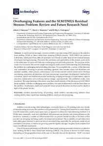
The investigation material consists of a polished surface sheet with thickness H0=1.28±0.02 mm. It was cut into strips with the width relation of 1:2:3 (20, 40 and 60 mm). The strips were cold rolled on laboratory two-high mill in the flat form with a reduction ratio of 15÷50 %. The strips were cut in order to obtain 80 mm long samples. Aiming to disturb the balance of stress, the samples were equally etched on one side with 20% NaOH solution. The rest of the sample was protected. The elastic line was measured by the instrument with the accuracy of 0.01 mm. Results and Analysis The deflection method. The state of residual stresses in cold rolled sheets is twodimensional, with the components in longitudinal and transverse direction. Residual stresses have dominant influence on the properties and shape of sheets. Their profile comprises the whole cross section, and the maximum is on the surface (Fig. 1a).
Fig. 1. Diagram of longitudinal residual stresses (a) and schematic presentation of elastic bending in cold rolled strips under the influence of residual stresses (b) Assuming that stresses are linearly distributed along the sheet and that they are constant along the width [2], the equilibrium diagram can be presented with the equation:
σ z = [ A1 hr + A2 ]
(1)
where: σz and σp are longitudinal stresses in the cross section area and on the surface; hr - relative thickness (y/H); A1, A2 – coefficients determined on the basis of boundary conditions. The evaluation of residual stresses by the deflection method is based on measurement of elastic bend of the sample. The elastic bend is formed due to unsymmetrical distribution of stresses along the section or their disturbance balance. In both cases longitudinal stresses are constant along the length and width of the sample, as well as the bending moment. This loading model corresponds to cantilever bending which elastic line can be presented with the equation:
y = a ⋅ z n2
(2)
RESIDUAL STRESSES IN COLD ROLLED NARROW STRIPS …
253
where: a - represents the coefficient (maximum bend); zn - relative longitudinal distance (z/L). The samples rolled in the flat form have symmetric distribution of longitudinal residual stresses (Fig. 1a) and balanced bending moments in relation to the longitudinal axis. The etching process causes the layer removal (thickness ∆) from one side, balance is disturbed and sample bending is as it is shown in Fig. 1b. According to the cantilever bending the bend is symmetric in relation to the transverse x-axis. Its measurement and approximation with the Eq. 2. can be performed for both ends of the sample. It means that the „0” point is exactly in the middle of 2L length and corresponds to the constrain point, and left and right sides correspond to the positive and negative segment of variable zn (z/L). In order to connect bending conditions to residual stresses, it is necessary to establishes a relation for their moment loading. The equation for estimation of longitudinal residual stresses can be obtained on the basis of equality between cantilever bending moment and residual stresses bending moment [3, 4]:
σp =
8 E (H - ∆ 2 )3 f
(3)
H 2 L2 ⎡⎢6 (∆ H ) − 6 (∆ H )2 + (∆ H )3 ⎤⎥ ⎣ ⎦
As it can be seen from the Eq. 3. the stress σp can be estimated, if the elastic modulus of materials (E), thickness of the removed layer (∆) and the dimension of elastic bend (f) are known. These parameters for chosen dimensions of samples, reduction ratio, elastic line, as well as for estimated stress values are shown in Table 2. Table 2. Parameters and results of experimental procedure and FEM simulation Reduct. Ratio ε , [%]
∆, [µm]
number elements
number nodes
f, [mm]
σzz, [MPa]
1
21.1
322
y=1,823⋅zn2 0.0174
2.446
79.04
12324
16000
2.161
79.93
2
21.5
331
y=1,622⋅zn2 0.0335
2.243
69.28
25596
32800
1.926
73.03
365
2 n
2.742
74.57
43344
55245
2.220
77.54
3
21.8
y = a⋅zn2
y=2,012⋅
mse
0.0662
f, [mm]
σp, [MPa]
Sample
FEM
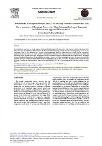
The measured values of sample bending after the surface layer removal and stress disturbance balance were approximated with the Eq. 2. The approximation results are shown in Fig. 2 and Table 2. The comparison between measured and estimated values (Fig. 2) and mean square error (mse in Table 1) demonstrate that the elastic line of bent sample can be described precisely with the equation for bent cantilever elastic line.
MJoM
254
METALURGIJA - JOURNAL OF METALLURGY 2 1.75
measured calculated
y, [mm]
1.5 1.25 1 0.75 0.5 0.25 0 -40
-30
-20
-10
0
10
20
30
40
z, [mm]
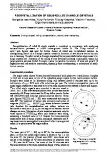
Fig. 2. Elastic line by sample 1 Residual stresses by the Eq. 3. are proportional to the expression f/L2. Therefore the reliability provided using the deflection method depends on the dimension (L). The estimated values of stress σp along the elastic line for chosen samples are shown in Fig. 3a. High values near the transverse axis become lower along the elastic line and reach approximately constant value. This dissipation is the consequence of measurement errors and elastic line approximation, as well as of nonhomogeneity of sample thickness appeared in rolling and chemical etching process. It means that for reliable determination of residual stresses it is enough to have total sample length (2L=Lu) twice bigger than the distance where the stress is nearly constant. If these data are demonstrated with relative relation between dimensions, then it is necessary to have Lu/B ≥ 2; 1.25 and 1 respectively to obtain H/B=1:15; 1:30 and 1:40. The deviation of measured elastic line values from theoretical conditions of cantilever bending can be considered as the approximation error, as well as the basic error in using the deflection method. In Fig. 3a. it represents the difference between measured and theoretical values of σp at the sample length which satisfy the specified criteria. If the difference between bottom and upper curved line is estimated on the basis of stress values the result ∆σp< ±5 MPa is obtained. In that way these values can demonstrate the accuracy in stress determination using the deflection method. FEM simulation. In the presence of residual stresses cold rolled strips change their geometry and properties. These changes can be identified by experimental measurements of stresses, and the FEM analisys can be applied by simulation of residual stresses. Accuracy of simulation was estimated based on the value of stress on the surface, shape of distribution and shape of the distortion model. FEM simulation was performed with the help of the outside load which is equivalent to the disturbed balance of residual stresses (Fig. 1a), with intention to confirm the effect on stress-strain state. In this regard ahalf of the sample was separated as equivalent cantilever with: -
position of constrain along transversal x-axis;
-
couple forces of outside loading opposite direction in regard to Fig. 1a.
RESIDUAL STRESSES IN COLD ROLLED NARROW STRIPS …
255
Fig. 3 Distribution of residual stresses along elastic line (a); results of FEM simulation for longitudinal residual stresses (b) and elestic line (c)
256
MJoM
METALURGIJA - JOURNAL OF METALLURGY
The simulation was done on the three chosen samples by using program MSC NASTRAN. Parameters of FEM (Table 2) and equivalent outside loading were chosen with the aim to satisfy starting hypothesis and to attain a high correlation with experimental results. By simulation on a half of the length of the sample, fields of values of stress tensor components on the space model were obtained as well as fields of values on y-z surface. The values of residual stresses and distribution in cross section are shown in Fig. 3b. At the halves of samples 1, 2 and 3, the lengths of 34, 30 and 26 mm can be separated respectively, where the constant value of normal stress σzz can be obtained. If these results are compared to experimental results (Fig. 3a and 3b) it can be concluded that the isolated sample lengths with the constant stress value in FEM simulation are 14, 15 and 16 mm higher for samples 1, 2 and 3 respectively. This confirms the reliable selection of the relations between sample dimensions in experimental process. Also, the initial bending condition that residual stress, i.e. bending moment, is constant along the strip length and width was satisfied. The stress σzz has linear distribution along thickness and in accordance with this a maximal value of the stress is on the surface. Other normal stress σxx, as well as all shear stresses have a symmetric distribution with regard to longitudinal z-axis and low values compared to stress. Third normal stress was practically equal to zero. In agreement with previously mentioned, equivalent Von-Mises's stress is a dominant factor which is caused by the longitudinal normal stress. The present shade at Von-Mises's stress expresses differences in the layer, which in absolute amount are similar to maximal values of stresses σxx, σxy, σyz and σzx. Significant point of simulations were also a numerous values of longitudinal stresses on the surface. In the Table 2 these results were comparatively shown with the calculated values of stresses using the Eq. 3. Practically identical values of stresses σp and σzz were obtained for the sample 1, whereas for samples 2 and 3 the absolute differences were 3.75 MPa and 2.97 MPa, respectively. These differences were minimal in the program of investigation which included different dimensions of samples, a wide range of reduction ratio of cold rolling (15÷50%) and values of residual stresses (45÷85 MPa). Equivalent outside loading caused elastic bending in the y-z surface (Fig. 2). Comparing the moving obtained by FEM simulation (Fig. 3c) with experimental results from Table 2, a good agreement may be noticed. Also, tests show that the moving obtained by FEM simulation can be precisely described by the Eq. 2. Maximal values of bend obtained in the experiment and by FEM simulation were also shown in parallel in Table 2. The highest difference obtained for the sample 3 and equals to 0.522mm. Notwithstanding the difference caused by unavoidable mistake of measurement of elastic bend of thin strips as well as the mistake of FEM, obtained coincidence for values of stress on the surface and elastic bend confirms the possibility of simulation by FEM on the selected model.
CONCLUSION Residual stresses in rolled sheets can be determined using the deflection method. The investigated samples have limited dimensions, and the preparation and measurement procedures are simple. The accuracy is ± 5 MPa for stress values of 70-80 MPa. The
RESIDUAL STRESSES IN COLD ROLLED NARROW STRIPS …
257
proper selection of equivalent exterior load and FEM parameters enables the residual stresses simulation with adequate accuracy and the prediction the effects of their balance disturbance. The obtained results in FEM simulation confirm the proper selection of samples and the accuracy of presumptions in the experimental process.
REFERENCES [1] Davies W.E., Sivilotti O.G., Tulett M.W., Production and Control of strip flatness in cold rolling, Metals Technology, 494-498, October (1975). [2] W. L. Roberts, Cold Rolling og Steel, Marcel Dekker, Inc., New York, (1978). [3] N. Tadić, Masters thesis, Faculty of Metallurgy and Technology, University of Montenegro, Podgorica, (2000). [4] M. Mišović, N. Tadić, Z. Ćulafić, The Residual Stresses in Cold Rolled Strip of AlMg4.5Mn Alloy, Journal of Metallurgy, No. 4, Volume 6, 241-249, Belgrade (2000). [5] V. Hauk, Eigenspnnunge, Entstehung-Messung-Bewertung, Vortragstexte eines Symposium, Deutsche Gesellschaft fur Metallkunde e.v., Band 1, 2-36, (1983). [6] Arnold Peiter, Nandbuch Spannungs Messpraxis – experimentelle ermittlung mechanischer spannungen, Viewing, Braunschweig/Wisbaden, (1992). [7] M. Mišović, M. Jelić, N. Tadić, Simulacija zaostalih napona primjenom FEM-a, Simpozijum-Deformacija i struktura metala i legura, 115-118, Beograd, Jun, (2002). [8] N. Tadić, M. Mišović, FEM Simulation of Residual Stresses in Cold Rolled Strips, 2nd International Conference on: DEFORMATION PROCESSING AND STRUCTURE OF MATERIALS, 201-205, Beograd, (2005).