Reuse of Post-consumer E-waste for Low Cost Micropower Distribution Daniel Ludois1, Jonathan Lee2, Patricio Mendoza3, Giri Venkataramanan4 Electrical & Computer Engineering University of Wisconsin Madison Madison WI, USA
[email protected],
[email protected],
[email protected],
[email protected]
Abstract—A novel medium voltage distribution system to electrify rural areas in developing nations using post consumer resources is presented in this paper. Using transformers repurposed from discarded microwave ovens to form a medium voltage microgrid, power may be distributed over an area of a few square kilometers while interconnecting a wide variety of generation sources and storage at a fraction of the cost of traditional systems. Microwave oven transformers (MOTs) are systematically characterized for optimal performance in these cases and construction guidelines are provided. A candidate distribution system using MOTs was constructed to deliver power from a small wind turbine to a small building at a horticulture field station. Results from this demonstration project are provided. Keywords- rural electrification; transformers; developing nations; recycling; post consumer resources; microwave; E-waste
I.
INTRODUCTION
It is a surprising fact to some that a quarter of all humanity, 1.6 billion people, live without access to electricity. In a large part, this lack of electricity access results from the high cost of extending and maintaining electric utilities in rural areas, especially where poverty is prevalent. Many researchers and practitioners have proposed solutions for off-grid generation at the home scale, e.g. small wind or solar, but these suffer from limited applicability to loads other than lighting due to weather variability and storage limitations. By interconnecting low power capacity, distributed generation and storage equipment between homes, community centers, schools, and other buildings the overall electric service, and thus quality of life, may be improved, in a more competitive fashion, in comparison with traditional electrification approaches [1, 2]. A system such as this one, typically an offgrid microgrid system, at the community/village scale is a viable solution but requires a distribution system capable of delivering power over areas on the order of square kilometers. Additionally, many renewable energy sources have geographic dependencies (small hydro or wind) and are not necessarily located near the end user(s). Low voltage distribution systems cannot accomplish the task of delivering this energy practically. A modern high voltage system would be ideal from a technical standpoint, but it would prove far too This work was primarily funded by the UW-Madison 2010 Climate Leadership Challenge, sponsored by the Global Stewards Society and administered by the Nelson Institute Center for Sustainability and the Global Environment. http://www.sage.wisc.edu/clc/
expensive. This poses an interesting problem -How does one move small amounts of power (kW) efficiently and affordably over square kilometers? This paper presents a novel solution to this quandary in the form of an intermediate voltage distribution transformer/distribution platform manufactured from repurposed post consumer resources. A. Impact on Humanity Bringing electricity to developing communities improves the quality of life, giving access not only to an energy resource, but also enables the use of current technology in the fields of education, health, and communications, among others. A study by the Human Development Resource Center in Dhaka, Bangladesh found that electrification is strongly associated with higher family income (65% higher than non-electrified villages), the empowerment of women, increased job availability (11 times as many workers were employed by electrified rather than non-electrified businesses), higher literacy rate (15% higher for electrified villages), greater human health (1.5% lower infant mortality and 24% higher immunization rates), and general improvements in agriculture, industry, and other commercial activities. Additionally, electrified households saw 16% of annual income attributable to electricity [3]. These social and economic benefits come at the cost of electrical connection per household, which varies greatly depending on the location, load level, population density, etc. In Kenya, for example, the ‘per household connection costs’ vary between $400 and $3000 [4]. With the system proposed in this paper, the cost of connection for rural communities would decrease to approximately $100 per household, helping to decrease the costs of electrification. In reducing electrification costs, the proposed system could expand electricity access for many communities in theory. From an environmental impact perspective, the system utilizes recycled materials from a microwave oven. In particular, recycling a microwave oven transformer improves waste management situations, and its reuse decreases manufacturing, combustion, and disposal stage environmental impacts [5]. B. Post Consumer Resource Transformer Concept Microwave ovens are disposed of by the millions worldwide every year. Thus, this single type of appliance has the potential to yield a significant number of post consumer resources. Of the components which compose a microwave oven, the high voltage transformer (high voltage in appliance terms) is rarely the culprit in oven failure. These transformers
operate at line frequency of 60/50 Hz with a primary voltage of 120/220 V and an average secondary voltage of approximately 2 kV. Power ratings vary considerably from oven to oven, but are usually in the vicinity of 1 kVA. These transformers possess ideal ratings to serve as a distribution transformer within the context of the intermediate voltage microgrid proposed earlier. Consequentially, the transformers of discarded microwave ovens embody the concept of “rightsizing,” yielding an optimal kilowatt scale rural electrification solution at the price of scrap materials. This is further exemplified in Fig. 1.
allow for quick estimations of certain MOT operating conditions. For example, it is easily seen that the MOT will have a magnetizing current of approximately one third of the rated current. Similarly, the voltage regulation will be driven mainly by the series impedance, with approximately 10% voltage drop at rated power (unity power factor).
R1
X1
X2
R2 Vout≈2.4kV
Vin=120V Figure 1. Operating plane of low voltage, medium voltage, high voltage systems, proposed system compromises through “right sizing”
II.
MOT CHARACTERIZATION & CONSTRUCTION
Basic knowledge of a microwave oven transformer (MOT) is essential to enable its application in rural electrification. MOTs are designed to be low cost, use minimal raw materials, operate with intermittent duty ratios, and self-limit fault currents in the event of a short circuit. Each of these traits impacts the capability of a MOT to perform as a distribution transformer. This section presents a typical MOT transformer equivalent circuit and accompanying parameters. Techniques to improve MOT performance are developed in detail and supported with experimental results. A. MOT Equivalent circuit A MOT has three separate windings: a line voltage primary winding, a high voltage secondary winding, and a low voltage filament winding, all wound around a steel “E-I” core. The filament winding may be removed, as it would no longer be used in this application. Additionally, magnetic shunts are present between the primary and secondary windings. These shunts saturate the core in the event of a short circuit condition. These features are illustrated in Fig. 2. To understand the “typical” MOT, 13 transformers from different oven manufacturers and models were compared. The mean values and standard deviations for the parameters are categorized in Tables I and II. While values in real units have a high variation, per unit parameters are more consistent and
N1:N2≈20 Figure 2. Profile view of MOT with primary, secondary, and filament windings on an E-I core with magnetic shunts. The equivalent circuit at the bottom does not show the magnetic shunts effect and ignores the filament winding. Table I. TRANSFORMER PARAMETERS REFERRED TO THE PRIMARY [Ω] R 1, R 2
X 1, X 2
RM
XM
Mean value
0.44
2.5
305.7
36.0
Standard Deviation
0.13
0.53
45.5
11.0
Table II. TRANSFORMER PARAMETERS REFERRED TO THE PRIMARY [PU] R 1, R 2
X 1, X 2
RM
XM
Mean value
0.03
0.21
25.8
3.0
Standard Deviation
0.003
0.084
6.23
1.34
It is important to remember that many who wish to develop a MOT distribution system will not possess sophisticated electronic measurement equipment to characterize transformers. A cost effective alternative may be performed with a simple length measuring tool as most transformer parameters can be calculated using geometric information. The DC resistance, rated power, rated current, and maximum flux
density can all be estimated using well-know transformer design equations outlined in the Appendix [4]. B. Efficiency & Performance Limitations An important realization must be made about the MOT parameters, specifically that the per-unit magnetizing inductance is low for distribution transformer. Low magnetizing inductance results in high magnetizing current and thus lower system efficiency. The magnetizing current under no load conditions is plotted in Fig. 3. To decrease the magnetizing current, the magnetizing inductance must increase proportionally. By removing the tertiary filament winding and magnetic shunts, the winding window widens allowing additional turns to be added to the primary winding. However, the consequences of removing the magnetic shunts must be evaluated before the primary is modified.
the series reactance should be noticeably larger in presence of the shunts. The MOT parameters were measured for the collection of transformers with and without shunts. A summary of the results of the new parameter measurements is shown in Table III. Comparing these results with those of Table II, it is seen that the magnetizing branch parameters are not considerably modified, neither is the series resistance. However, the series reactance has noticeably changed with the removal of the magnetic shunts. In general, the MOT series impedance moves towards the real axis on the complex plane, as shown in Fig. 4.
Table III. . TRANSFORMER PARAMETERS REFERRED TO THE PRIMARY [PU], NO SHUNTS R 1, R 2
X 1, X 2
RM
XM
Mean value
0.031
0.066
23.0
2.56
Standard Deviation
0.004
0.018
6.21
1.12
Figure 4. The MOT series impedance in the complex plane shows a migration from higher to lower reactance in all studied cases. Resistances are not substantially modified.
Figure 3. Waveforms at the MOT terminals under no load condition, including primary voltage, secondary voltage and primary current. Blue-unmodified transformer, Green- shunts removed and 6 turns added to primary winding.
The series equivalent reactance of a MOT, which is high for a distribution transformer application, is directly affected by the magnetic shunts. As mentioned earlier, the magnetic shunts act as a current limiter in case of a short circuit. However, this self-limiting capability is performed at the expense of larger series impedance, specifically a larger reactance. It can be observed in Fig. 2 that the windings are not built concentrically as it is usually done in commercial transformers. Moreover, the magnetic shunts provide an alternative path for the flux of each individual winding, effectively acting as a leakage. Therefore,
Figure 4 indicates that MOT performance improves as the removal of the shunts lowers the series reactance resulting in better regulation. With shunt removal justified, space exists for additional turns to be added to the primary winding to increase the magnetizing inductance. It should be noted that after removing the shunts over-current protection must be provided by external means such as fuses or circuit breakers. It is apparent in the secondary voltage and primary current waveforms in Fig. 3 that the core is saturating under no load conditions. The magnetizing flux density Bm in the core of a transformer using sinusoidal excitation is defined by the applied primary voltage VpRMS, core area AC, number of primary turns Np, and operating frequency f in (1) [6].
Bm =
V pRMS 4.44 ⋅ N p ⋅ AC ⋅ f
(1)
The saturation of the core and high magnetizing current can be mitigated simultaneously by adding turns to the primary winding. MOTs operate at the cusp of saturation, thus a small number of turns (~10 turns) added to the 120V primary is sufficient to achieve significant performance gains. The performance gains for shunt removal with additional turns are compared with the original MOT in Figures 3 & 5. Notice the removal in shunts and addition of turns extends the MOT operating space and efficiency. Although, the additional turns reduce secondary winding voltage slightly, it does not compromise the distribution voltage efficacy.
100.00 90.00
Efficiency (%)
80.00 70.00 60.00 50.00 40.00 30.00 20.00
Figure 6. MOT enclosure realized with metal paint can and PVC end caps
10.00 0.00 0.00
100.00
200.00
300.00
400.00
500.00
600.00
700.00
Load Power (W) With shunts
Without shunts
With new turns
Figure 5. Efficiency curve of one of the MOTs from the collection. The experimental results validate the increase of the power range that the MOT can handle after the magnetic shunts are removed. Additional primary turns increase transformer efficiency by 5%.
C. Distribution Transformer Package With the electrical characteristics of the MOT clearly defined and managed, a suitable package for the system may be developed. To keep in the spirit of repurposing post consumer resources, a metal paint can makes an ideal weather proof container. After attaching a mounting bracket and insulating terminal bushings to the lid, which may take the form of PVC pipe end caps, the distribution MOT package is illustrated in Fig. 6. The can may be filled with dielectric oil but particular care should be given to the type of oil used due to effects on the wire insulation. The oil is essential for cooling the MOT as it was not originally intended for continuous duty. Additionally, the oil will provide a significant thermal improvement over open air cooling.
III.
DEMONSTRATIONS & TEST INSTALLATION
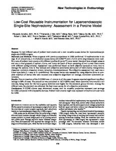
After performing laboratory research and development, an outdoor demonstration project was pursued in cooperation with members from the UW-Madison College of Agricultural and Life Sciences. Previous work on a wind turbine was completed at the West Madison Agricultural Research Station (WMARS) used for field work in the vicinity of campus. The WMARS site proved to be an ideal location for a prototype distribution line using the previously described MOT concept. An aerial view of the site location is shown in Fig. 7. The wind turbine site is rated for 500W, and it is equipped with battery storage and controls. The identified load for this wind energy was a prefabricated tool shed, which was not grid connected, but contained preinstalled electrical wiring and associated components for future electrification. The project goal was to connect the wind turbine and the tool shed load through a 500 ft, 2kV distribution line. A number of steps were involved in the construction of the MOT distribution line. First, the anticipated load of the tool shed needed to be understood. Students and faculty working on this WMARS land primarily use this shed in the growing season. In the shed, consumer electronics, hand tools, microscopes, and CFL lighting are used. Therefore, heuristically, the loads in the shed will vary from 10 to 1000W peak. The MOT system is ideally matched for this load level with each MOT having a power capacity of about 1kW, which supports their system candidacy. Second, the physical construction of the distribution line was decided upon. The frequent traffic of large farming equipment in this area required the distribution line to be placed underground, not overhead. This decision would also increase safety and decrease undesirable aesthetic appearance of power lines and poles. With trenching and backfilling equipment, the process of creating an underground distribution system did not prove too difficult although the level of difficult of this decision in other projects may vary.
SUMMARY & CONCLUSIONS
IV.
A low cost distribution transformer for rural electrification constructed from post consumer resources is presented in this paper. The recycling of microwave oven transformers (MOTs) is an appealing solution for small electricity distribution systems and allows the interconnection of small distributed energy resources to the grid and/or local loads, maintaining a right-sizing and cost-effectiveness balance. The collection, conditioning, testing and certification of re-purposing the ewaste can produce job-streams while reducing waste. Electrification with the proposed system would allow for the reduction of greenhouse gas emissions through the reduction of combustion, fuel consumption displacement, and energy savings in avoiding additional manufacturing. Social and economic benefits include improvements in quality of life, education, health and communications, and reduced ‘per household connection cost’ to access to electricity. The limitations of MOTs regarding low magnetizing inductance, high leakage inductance, and efficiency are addressed. Removing magnetic shunts and inserting additional turns into the primary winding improve MOT performance significantly. The design modifications are supported with experimental results. Finally, a demonstration distribution line was constructed to connect a small turbine to a remote utility shed, which demonstrates system technical viability. Figure 7. Aerial view of the WMARS distribution line site (top), photographs of the MOT transformers at the sending and receiving ends (bottom).
Finally, the physical MOT based distribution transformers were created for this project. Two MOT(s) were needed. The first, located at the wind turbine, would act as the step-up transformer, raising the inverter voltage of 120VAC to 2kV. The second transformer, located at the shed, would act as the step-down transformer, lowering the 2kV voltage to a usable 120VAC for consumer electronics and other tool shed loads. This medium voltage distribution system decreases the current of the distribution line, thus decreasing line loses and increasing efficiency with respect to lower voltage level options in this application as shown in Table IV. Table IV. LOW & HIGH VOLTAGE TRANSMISSION LINE COMPARISON Metric Line Length [m] Voltage [V] Power [W] Current [A] Line Material Gauge [AWG] Line Resistance [Ω] Voltage Drop [V] Voltage at Load [V] Voltage Drop Line Loss [W] Power to Load [W] Line Loss [%] Line Efficiency [%]
120V Option 137.16 120 1000 8.33 Copper 18 2.8 23.3 96.7 19.42% 194.2 805.8 19.42% 80.58%
MOT Option 137.16 2000 1000 0.5 Copper 18 2.8 1.4 1998.6 0.07% 0.7 999.3 0.07% 99.93%
APPENDIX A geometrical study can be performed on a MOT using simple measuring tools that may be available in places where electrical laboratory equipment is not. Usually, this method requires tools such as a ruler, although more precise tools such as a vernier caliper are recommended. Measurements of the core, as well as the number of turns of each winding are required. Using the measurement definitions in Fig. 8, the following quantities can be calculated: Core cross-sectional area [cm2]:
AC = D ⋅ B
(2)
Window area [cm2]:
WA = E ⋅ F
(3)
Area product [cm4]:
AP = AC ⋅ WA
(4)
Maximum flux density [T]:
Bm =
V pRMS 4.44 ⋅ N p ⋅ AC ⋅ f
(5)
Where Np is the number of turns of the primary, and the applied rms primary voltage is VpRMS at a frequency f.
Rated power:
P = 2 ⋅ Ap ⋅ Bm ⋅ J w ⋅ kW ⋅ f
(6)
noted that Bm was measured indirectly via Faraday’s law (5) by measuring the filament winding voltage under primary winding excitation.
Where the current density and the winding fill factor are assumed to be Jw = 4 [A/mm2] and kw = 60% respectively.
Table V. SELECTED MOT PARAMETERS FROM MEASUREMENTS AND GEOMETRIC ANALYSIS PREDICTIONS
Bm [T]
P [W]
Ω] Rp [Ω
Rs [Ω Ω]
Mtot [kg]
Prediction
1.889
565.4
0.412
163.0
2.83
Measurement
1.893
531.2
0.67
166.5
2.72
Example values:
B
A = 71.8 mm B = 58.5 mm C = 86 mm
D/2
D = 28.5 mm
D A
E = 43 mm
* measured at the maximum efficiency operating point
The flux density is near 2 T, a high value even for the best iron laminations available. This estimation agrees with the observations of Section II.B where the magnetizing current is high and distorted due to saturation.
F = 14 mm Additionally,
E F
NP = 130 NS = ~2400
F C
Figure 8. Transformer measurement definitions for parameter estimation
Additionally, if the wire diameter φ is measured in each winding, the primary & secondary winding resistance may be calculated assuming using σCu = 5.96·107 [S/m].
Rp =
Lp
σ Cu S p
,
Rs =
Ls σ Cu S s
(7)
Where the primary and secondary wire length are (8) followed by the mean winding length (9).
L p = Lm ⋅ N p , Ls = Lm ⋅ N s Lm = 2 ⋅ B + 2 ⋅ D + 4 ⋅ F
ACKNOWLEDGMENT The authors would like to thank the members of the Global Stewards Society for sponsoring the UW-Madison Climate Leadership Challenge, Professor Tracey Holloway of the Nelson Institute Center for Sustainability and the Global Environment (SAGE), and the West Madison Agricultural Research Station (WMARS) staff for their support and guidance. The student authors of this paper were supported by the Wisconsin Electric Machines and Power Electronics Consortium, USA Department of Energy’s 20% By 2030 Award Number, DE-EE0000544/001, titled 'Integration of Wind Energy Systems into Power Engineering Education Programs at UW-Madison’, the Fulbright-CONICYT scholarship program, US Air Force Sustainable Infrastructure Program’s ESTCP office through the Distributed Power Systems for Sustainable Energy Resources project of United Technologies Research Center, subcontracted to UW-Madison.
(8) (9)
REFERENCES [1]
The wire sections of the primary and secondary are calculated from the diameter as follows: [2]
Sp =
πφ 2p 4
, Ss =
πφ 4
2 s
(10)
Transformer volume and mass (useful for checking purposes)
VFe = ( A ⋅ C ) − (2 ⋅ E ⋅ F ) ⋅ B
(11)
VCu = L p ⋅ S p + Ls ⋅ S s
(12)
M tot = VCu ⋅ ρCu +VFe ⋅ ρFe
(13)
[3]
[4]
[5]
Where the material densities are ρCu = 8940 [kg/m3] and ρFe = 7650 [kg/m3]. Using the example values in Fig. 8, desired MOT characteristics are calculated in Table V. It should be
[6]
M. Illindala, A. Siddiqui, G. Venkataramanan, and C. Marnay, "Localized aggregation of diverse energy sources for rural electrification using microgrids," Journal of Energy Engineering-ASCE, vol. 133, pp. 121-131, Sep 2007. Invited Paper in Special issue on Distributed Generation. G. Venkataramanan, C. Marney, “A larger role for microgrids” IEEE Power and Energy Magazine, May/June 2008. Fulkerson, W., Levine, M.D., Sinton, J.E., Gadgil, A. (2005). Sustainable, efficient electricity service for one billion people. Energy for Sustainable Development, Volume 6 No. 2, 26-34. World Bank, Columbia Earth Institute, Kenya Power and Lighting Company. (2007). National Electrification Coverage Planning; Investment Costing Estimation Model U.S. Environmental Protection Agency, Climate Change and Waste Fact Sheet: Reducing Waste Can Make a Difference. (Online) Available: http://epa.gov/climatechange/wycd/waste/downloads/cc-waste.pdf C.W.T. McLyman, Transformer and Inductor Design Handbook, Marcel Dekker, Inc., 3rd Edition, Revised and Expanded, 2004. ISBN: 0-82475393-3