WHYP on a 68HC12 Richard E. Haskell CSE Dept., Oakland University Rochester, Michigan 48309 email:
[email protected] and
Michael Trader EDS, Embedded Systems Engineering email:
[email protected]
Abstract The 68HC12 is the latest family of Motorola 8-bit microcontrollers. It is upward compatible from the 68HC11 (at the source code level but not the object code level) but contains many new instructions and addressing modes which considerably enhance its speed and code efficiency. This paper describes the implementation of a subroutine-threaded Forth called WHYP on the MC68HC812A4 and MC68HC912B32 parts. An example of using two MC68HC912B32 microcontrollers to simulate an engine controller will be described.
Introduction WHYP (pronounced whip) stands for Words to Help You Program and is a subroutine threaded Forth designed specifically for embedded systems [1-4]. Versions of WHYP have been written for both the Motorola 68HC11 and 68332 families of microcontrollers. Recently WHYP has been ported to the new Motorola 68HC12 family of microcontrollers. The new addressing modes of the 68HC12 make this a much more efficient implementation than the one on the 68HC11. WHYP consists of two parts: a C++ host program running on a PC and a 68HC12 kernel running on the target system. The C++ program communciates with the target 68HC12 system through an asynchronous serial line. The dictionary for all WHYP words is maintained in the C++ program on the PC. The WHYP words shown in Table 1 exist only in the C++ program on the PC. These contain compiler-type words such as BEGIN...UNTIL and other words that need to be handled immediately. The kernel, written entirely in 68HC12 assembly language, is a little over 2 Kbytes in size and consists of short 68HC12 subroutines for the 125 WHYP words shown in Table 2. When executing, the WHYP kernel waits for a 16-bit address to be sent by the C++ program running on the PC and then jumps to the subroutine at that address. The words in Tables 1 and 2 form the core WHYP words that would be available on any 68HC12 system and use only a little over 2 Kbytes of target memory. All other words, including many 68HC12-specific words are available as colon definitions in files that can be loaded as needed. For a number of years WHYP has been used successfully in a course on embedded systems taught at Oakland University. The material used in this course has been brought together in a forthcoming textbook in which WHYP plays a central role [5].
Table 1 Core WHYP words resident in the C++ program ' ( , ." : ; AGAIN ALLOT
ASCII BEGIN BYE C, CLI CONSTANT CONTROL CREATE
DECIMAL DO DOES> ELSE FOR HEX IF INT:
LITERAL LOAD LOAD.S19.FILE LOAD>TSEG LOOP NEXT RECURSE REPEAT
RTI; SAVE.HEADERS SAVE.TSEG SEE SEI SHOW STEP THEN
UNTIL VALLOT VARIABLE WHILE [ \ ]
Table 2 Core WHYP words resident in the target system ! (,) (.") (;CODE) (C,) (CREATE) (DLIT) (DO) (LIT) (LOOP) * */ + +! -ROT . .R .REG .S /
/MOD 0< 0= 0> 1+ 12* 2+ 22/ 2DROP 2DUP 2OVER 2SWAP 10MS.DELAY < >=
>R ?branch ?DUP ?NEGATE @ ABS AND branch C! C@ calc.output CMOVE CMOVE> CR D+ DD. DABS DEPTH DNEGATE DODOES
DONEXT DOVAR DROP DUMP DUP EE! EEC! EMIT ERASE.BULK EXECUTE EXIT FALSE FDIV fill.weights firerules FLIP HERE I IDIV INVERT LEAVE
LSHIFT M* M/MOD MASK MAX MIN MOD MOVE NEGATE NIP OR OVER PICK R> R>DROP R@ ROLL ROT RP! RP@ RSHIFT
S.FILE S>D SNDSUB SP! SP@ SWAP TRUE TUCK U. U/ U2/ U< U U>= UD. UM* UM/MOD XOR [']
WHYP on a 68HC12 In WHYP on the 68HC12 the index register X is used for the data stack pointer and the system stack pointer is used as the return stack pointer. The new instructions and addressing modes on the 68HC12 makes for efficient implementation of basic WHYP words. For example, the words DUP and OVER are implemented as shown in Figure 1. The instruction MOVW can move a 16-bit word from a source memory location to a destination memory location. For example, in the definition of OVER in Figure 1 the source operand 2,X will add 2 to X to get the address of w1. The destination operand 2,-X will predecrement X by 2 and then store the source value (w1) at the new address in X. ; DUP ( w -- w w ) ; Duplicates the top stack item DUPP MOVW 0,X,2,-X RTS ; OVER ( w1 w2 -- w1 w2 w1 ) ; Copy second stack item to top OVER MOVW 2,X,2,-X RTS
Figure 1 Example of basic 68HC12 code words
The 68HC12 has several new extended multiplication and division words. For example, the instruction EMUL will multiply the 16-bit unsigned value in D by the 16-bit unsigned value in Y and leaves the 32-bit unsigned product in Y:D. This instruction can be used to define the WHYP word UM* as shown in Figure 2. The instruction LDD 2,X+ pops the top of the data stack into D by using the postincrement indexed addressing mode. In this case, the value pointed to by X is loaded into D and then X is incremented by 2. There is also an extended signed multiplication instruction, EMULS, that can be used in a similar way to define the WHYP word M* that will return a 32-bit signed product. The extended division words, EDIV and EDIVS, will divide unsigned and signed 32-bit dividends (in Y:D) by 16-bit divisors (in X) to produce 16-bit quotients (in Y) and 16-bit remainders (in D). For example, EDIV can be used to define the WHYP word UM/MOD as shown in Figure 3. The instruction EDIVS can be used in a similar fashion to define the WHYP word M/MOD. The remainder in this case has the same sign as the dividend. WHYP therefore uses symmetric division rather than floored division.
; UM* ; UMSTA
( u u -- ud ) 16 x 16 = 32 Unsigned multiply. Return double product. LDD LDY EMUL STD STY RTS
2,X+ 2,X+ 2,-X 2,-X
Figure 2 Using the EMUL instruction to define UM* * * UMMOD
UM/MOD ( udl udh un -- ur uq ) 32/16 = 16:16 Unsigned divide of a double by a single. Return mod and quotient. PSHX LDY LDD LDX EDIV PULX LEAX STD STY RTS
2,X 4,X 0,X 2,X 2,X 0,X
Figure 3 Using the EDIV instruction to define UM/MOD
The 68HC12 has some built-in instructions that make it easy and efficient to implement fuzzy control. These include the instructions MEM for computing fuzzy membership grades, REV and REVW for evaluating rules, and WAV for computing weighted averages. These instructions are used in the WHYP words fill.weights, firerules, and calc.output listed in Table 2. Other high-level WHYP words which use these words make it easy to implement fuzzy control in WHYP [6].
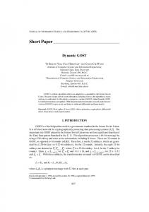
Engine control simulator using a 68HC12 In the automotive industry it would be useful when designing a new engine control module (ECM), sometimes referred to as an Engine Management System (EMS) or PCM (Powertrain Control Module), to be able to simulate and/or emulate both the PCM and the engine so that algorithms can be tested before an actual PCM is manufactured. In an attempt to study such a co-simulation environment, two MC68HC912B32 evaluation boards were used to show how WHYP can be used to help validate control algorithms intended for use on real hardware in the future. For this example, a simple engine control and behavior were emulated. Figure 4 shows a block diagram of the primary components of this co-simulation experiment. Note that one of the 68HC12 boards is being used as an Engine Management System, while the other 68HC12 is simulating the generalized engine behavior model. The third component in Figure 4 is a PC. The same asynchronous communication line that communicates with the WHYP kernel is used during the execution of the engine control algorithms to display running parameters. This remote display module (RDM) is created in Visual Basic 5.0 and displays simple outputs such as engine speed (RPM) and allows the user to modify environmental parameters such as throttle position and gear. Other parameters such as ambient temperature, barometric pressure, load, or grade can be added later. Figure 5 illustrates the RDM interface. Several characteristics unique to the 68HC12 were useful while developing the software for the engine model and control modules shown in Figure 4. The expanded instruction set not only enriches the math and addressing modes, as mentioned earlier, but also adds two lookup table operations, one for byte sized data, and one for word sized data (TBL and ETBL). Figure 6 shows the primitive WHYP word created to allow use of the ETBL instruction. The function W.LOOKUP takes as inputs the address of a table of 16-bit values and an 8-bit fractional component and returns an interpolated 16-bit value on the WHYP data stack.
Timer Channels
Crank Cam
Timer Channels 4
Fuel Spark 2
HC12 Engine Simulator
SPI
HC12 Engine Management System SPI
SCI PC/RDM
Engine/EMS Co-Simulation
Figure 4 Block diagram of the co-simulation system
Figure 5 Remote data module user interface
; 16 BIT Table Lookup wrapper * W.LOOKUP ( addr frac -- interp ) WLOOKUP LDD 2,X+ LDY 0,X ETBL 0,Y STD 0,X RTS
Figure 6 – ETBL WHYP wrapper function
Another significant improvement found in the 68HC12 family of microcontrollers is the flexibility in configuring the timer channels. While timer channels are not a new addition to microcontrollers, the ability to configure (and reconfigure) any of the eight 68HC12 timer channels as either an input capture or an output compare circuit is a powerful design option. All eight timer channels were used on both 68HC12 boards shown in Figure 4. In one implementation, 6 channels are input captures and two are output compares (the EMS module), while the engine simulator only outputs crank
and cam signals as timed signals, using the other 6 timer channels as input captures to monitor, in real time, applied fuel and spark signals.
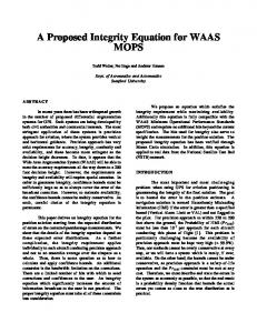
The co-simulation timing signals Many more than eight signals are passed between an actual engine and its control module. However, the eight signals selected to use with the eight timer channels found in the 68HC12 are those that require the quickest response and the most precise coherency. These signals can be sampled using a digital oscilloscope or logic state analyzer to verify proper edge location and pulse width. Figure 7 shows an example of a timing diagram taken from a logic state analyzer early in the development cycle of the control and behavior algorithms. All other behavior and control signals can be passed between the test modules via the SPI (serial peripheral interface).
Figure 7 Logic state trace of timer signals
Figure 7 illustrates the interaction of the engine simulator and the engine control module via timing signals. The engine creates a crank and cam signal based on an RPM value. The engine control module decodes the engine position from these signals and then schedules a fuel pulse which indicates the energizing of an injector solenoid. The engine simulator measures the pulse width of the fuel injector pulse and adjusts the RPM accordingly. The other timing signals shown on Figure 7 are used to measure interrupt service routine execution times as well as to analyze system throughput.
Summary This paper has described how the subroutine-threaded Forth language, WHYP, has been implemented on Motorola’s new 68HC12 family of microcontrollers. The new instructions and addressing modes on the 68HC12 make this implementation of WHYP particularly efficient. An example of using two MC68HC912B32 microcontrollers to simulate an engine controller and engine model has been described.
References 1.
R. E. Haskell, "Design of Embedded Systems Using WHYP," Proc. 1997 Rochester Forth Conference, Rochester, NY, June 25-28, 1997.
2.
R. E. Haskell, "WHYP – A C++ Based Version of ouForth for the Motorola 68HC11," Proc. 1995 Rochester Forth Conference, Rochester, NY, pp. 46-49, June 21-24, 1995. R. E. Haskell, "ouForth – a Subroutine Threaded Forth for Embedded Systems," Proc. 1993 Rochester Forth Conference, Rochester, NY, pp. 62-66, June 23-26, 1993. R. E. Haskell, "Design of a Subroutine Threaded Forth for Embedded Systems," Proc. 1992 FORML Conference, Pacific Grove, CA, pp. 58-62, November 27-29, 1992. Richard. E. Haskell, Design of Embedded Systems Using 68HC11/12 Microcontrollers, Prentice Hall, Upper Saddle River, NJ, To be published. R. E. Haskell, "Fuzzy Control in Forth," Proc. 1994 Rochester Forth Conference, Rochester, NY, pp. 28-31, June 22-25, 1994.
3. 4. 5. 6.