LUBY-TRANSFORM (LT) codes [1] were the first practi- cal examples of a rateless erasure correcting code which approaches capacity for increasing message ...
MITSUBISHI ELECTRIC RESEARCH LABORATORIES http://www.merl.com
Ripple Design of LT Codes for BIAWGN Channels
Sorensen, J.H.; Koike-Akino, T.; Orlik, P.; Ostergaard, J.; Popovski, P.
TR2014-007
January 2014
Abstract This paper presents a novel framework, which enables a design of rateless codes for binary input additive white Gaussian noise (BIAWGN) channels, using the ripple-based approach known from the works for the binary erasure channel (BEC). We reveal that several aspects of the analytical results from the BEC also hold in BIAWGN channels. The presented framework is applied in a code design example, which shows promising results compared to existing work. In particular it shows a great robustness towards variations in the signal-to-noise power ratio (SNR), contrary to existing codes. IEEE Transactions on Communications
This work may not be copied or reproduced in whole or in part for any commercial purpose. Permission to copy in whole or in part without payment of fee is granted for nonprofit educational and research purposes provided that all such whole or partial copies include the following: a notice that such copying is by permission of Mitsubishi Electric Research Laboratories, Inc.; an acknowledgment of the authors and individual contributions to the work; and all applicable portions of the copyright notice. Copying, reproduction, or republishing for any other purpose shall require a license with payment of fee to Mitsubishi Electric Research Laboratories, Inc. All rights reserved. c Mitsubishi Electric Research Laboratories, Inc., 2014 Copyright 201 Broadway, Cambridge, Massachusetts 02139
MERLCoverPageSide2
IEEE TRANSACTIONS ON COMMUNICATIONS, ACCEPTED FOR PUBLICATION
1
Ripple Design of LT Codes for BIAWGN Channels Jesper H. Sørensen, Toshiaki Koike-Akino, Philip Orlik, Jan Østergaard, and Petar Popovski
Abstract—This paper presents a novel framework, which enables a design of rateless codes for binary input additive white Gaussian noise (BIAWGN) channels, using the ripple-based approach known from the works for the binary erasure channel (BEC). We reveal that several aspects of the analytical results from the BEC also hold in BIAWGN channels. The presented framework is applied in a code design example, which shows promising results compared to existing work. In particular it shows a great robustness towards variations in the signal-to-noise power ratio (SNR), contrary to existing codes. Index Terms—
I. I NTRODUCTION
L
UBY-TRANSFORM (LT) codes [1] were the first practical examples of a rateless erasure correcting code which approaches capacity for increasing message length, k. Such rateless codes may potentially generate an infinite amount of encoded symbols. For the BEC channel, decoding is possible when n = (1 + ǫ)k encoded symbols have been received, where ǫ approaches zero for increasing message length. An important element in the design of LT codes for the binary erasure channel (BEC) is a parameter called the ripple. The performance depends significantly on how this parameter evolves during decoding, and thus successful designs have mostly focused on this parameter, and the heuristics around it. Although LT codes were originally developed for the BEC, several works have tried to extend the field of applications for these codes, including [2]–[6]. Design of Raptor codes, which concatenate an LT code and a fixed rate error correcting code, for the binary symmetric channel (BSC) and binary-input additive white Gaussian noise (BIAWGN) channel is studied in [2]. This design is based on the Gaussian approximation method [3], which is used to derive constraints for the degree distribution of the LT code. In [4], [5], approaches based on extrinsic information transfer (EXIT) charts are applied to the design of LT and Raptor codes, respectively. Another design of Raptor codes for arbitrary symmetric channels is presented in [6], where an analogue to the ripple is defined as the increase in correct bit estimates in a given decoding round. The design is based on finding an optimal value for this measure. Other classes Manuscript received February 8, 2013; revised August 24 and November 26, 2013. The editor coordinating the review of this paper and approving it for publication was A. Graell i Amat. J. H. Sørensen, J. Østergaard, and P. Popovski are with Aalborg University, Department of Electronic Systems, Fredrik Bajers Vej 7, 9220 Aalborg, Denmark (e-mail: {jhs, jo, petarp}@es.aau.dk). J. H. Sørensen is also with Mitsubishi Electric Research Laboratories (MERL), 201 Broadway, Cambridge, MA 02139, USA. T. Koike-Akino and P. Orlik are with Mitsubishi Electric Research Laboratories (MERL), 201 Broadway, Cambridge, MA 02139, USA (e-mail: {koike, porlik}@merl.com). Digital Object Identifier 10.1109/TCOMM.2013.122013.130116
of rateless codes based on low density parity check (LDPC) codes and turbo codes are presented in [7]–[9]. In [7] a rateless code is designed for the BIAWGN channel through random, potentially infinite, sampling of the encoded bits of a nonbinary LDPC code. In [9] the rateless property is achieved through copying and permuting an LDPC code. Puncturing is used to achieve more accurate rate compatibility. The work in [8] presents a rateless code based on a potentially infinite bank of interleavers at the output of a turbo code. The contribution of this work is two-fold. The first contribution is a derivation of a novel framework of LT codes in the BIAWGN channel. Interestingly, we verify that key analytical results presented in [1] for the BEC also hold in the BIAWGN channel with some new interpretations. The second contribution is a development of a new design methodology of LT codes for the BIAWGN channels by making use of our framework. The proposed framework enables us to design LT codes by using a ripple-based approach, which was originally applied for the BEC. This enables a simpler and more efficient design due to the tractability of the BEC compared to noisy channels. This is reminiscent of surrogate designs of LDPC codes [10], in which a noisy channel is modeled as an equivalent erasure channel, where equivalence is with respect to e.g. capacity. Using the equivalent model, it is possible to design the LDPC codes as if intended for application in an erasure channel. The design approach applies density evolution, which simplifies greatly in the case of BEC. As in this work, the result is a more tractable design procedure. The design proposed in this work operates in the binary field, contrary to [7], thus these works are significantly different in terms of complexity. Contrary to [9], the codes proposed in this work are suitable for low and moderate sized message lengths. Like for [7] and [9], the work in [8] differs from this work in the class of codes applied in the rateless scheme. The works presented in [2]–[6] all consider LT codes, either as part of a Raptor code or solely, as is the case in this work. However, this work carries considerable novelty in the design approach. The work presented in this paper is an extension of the work in [11]. The framework is applied in a new way, which proves to perform significantly better. This is verified through more extensive numerical evaluations and comparisons with state-of-the-art solutions. The remainder of this paper is organized as follows. A description of the system model and an introduction to LT codes and their decoding are given in section II. Section III presents the framework for ripple-based designs in BIAWGN channels. An example of a design applying the presented framework is given in section IV. Numerical evaluations are presented in section V followed by conclusions in section VI.
c 2013 IEEE 0090-6778/13$31.00
2
IEEE TRANSACTIONS ON COMMUNICATIONS, ACCEPTED FOR PUBLICATION
Input symbols
II. BACKGROUND
X1
X2
X3
X4
In this section the system model is introduced along with a description of LT codes and their decoding. l mi,o
A. System Model
l mo,i
We consider a single link communication channel with binary input and additive white Gaussian noise (BIAWGN). This channel is used to transmit a message of length k, X = [X1 , X2 , ..., Xk ], Xi ∈ {0, 1}, from node A to node B. This message is encoded using an LT code producing a codeword of length n, X ′ = [X1′ , X2′ , ..., Xn′ ], Xi′ ∈ {−1, 1}, where n is potentially infinite. The signal-to-noise power ratio (SNR), γ, is defined as Es /N0 , where Es is energy per transmitted symbol and N0 is the noise spectral density. During the transmission of the encoded message, γ is assumed to be constant and known at both transmitter and receiver. Hence, for each real-valued binary channel input Xi′ , we have the output Yi = Xi′ + Ni ,
(1)
where Ni ∼ N (0, N0 /2), with N (·) being the normal distribution. Knowledge of γ is necessary at the receiver, since it has been shown that no single LT code is universally capacity approaching in noisy channels [2]. By universally, we mean independent of the channel parameter, which in the case of BIAWGN is the SNR. Hence, optimizing the degree distribution requires knowledge of γ. One could argue that with knowledge of γ, the transmitter can just adapt the modulation and coding scheme instead of using a rateless code. However, in practice, only an estimate will be available, which means a non-zero probability of error still exists. Retransmission mechanisms must then potentially be invoked, which has a large impact on throughput and delay. In this work we optimize for γ in the design of the LT code, but we also show that the proposed code design is very robust towards estimation errors. Degree distributions can be found, which perform close to optimally across a wide range of SNRs, thus softening the requirement of SNR knowledge at the transmitter. B. LT Codes The transmitting message X = [X1 , X2 , ..., Xk ] are referred to as input symbols. From these input symbols a potentially infinite amount of encoded symbols, also called output symbols, are generated. Output symbols are exclusiveor (XOR) combinations of input symbols. The number of input symbols used in the XOR is referred to as the degree of the output symbol, and all input symbols contained in an output symbol are called neighbors of the output symbol. The output symbols of an encoder follow a certain degree distribution, Ω, where Ω(d), d = 1, 2, ..., k is the probability that an output symbol has degree d. The degree distribution is a key element in the design of good LT codes. The encoding process of an LT code can be broken down into three steps: 1) Randomly choose a degree d by sampling Ω(d). 2) Choose uniformly at random d of the k input symbols. 3) Perform bitwise XOR of the d chosen input symbols. The resulting symbol is the output symbol.
Output symbols
Fig. 1.
X1´
X2´
X3´
X4´
X5´
Graphical representation of an LT code.
This process can be iterated as many times as needed, which results in a rateless code. The terms degree and neighbors originate from bipartite graphs, which are often used to visualize a code. In Fig. 1, an example of LT codes is shown, where the upper nodes represent input symbols and lower nodes represent output symbols. An edge between two nodes indicates that they are neighbors, and the number of edges emanating from a node is the degree of the corresponding symbol. A widely used decoder for LT codes is the belief propagation (BP) decoder, which is the focus of this work. Depending on the channel, the BP decoder can be implemented in different variants with different structural and computational complexities. The following subsections describe the cases of the BEC and BIAWGN channels. C. Decoding for BEC In the BEC, only non-erased symbols are included in the decoding, which means all output symbols in the decoder are completely reliable. This makes it possible to apply the BP decoder in a quite simplistic form, since it implies that the decoder can merely perform the logical XOR operations inversely from the encoding process. Initially, all degree-1 output symbols are identified and their neighboring input symbols, which are identical to the output symbols, are moved to a storage referred to as the ripple. Symbols in the ripple are processed one by one; more specifically they are XOR’ed with all output symbols who have them as neighbors. Once a symbol has been processed, it is removed from the ripple and considered decoded. In terms of the graphical representation in Fig. 1, this is visualized by removing all edges emanating from the processed input symbol, except the edge connecting it with the output symbol, which revealed its value. This will potentially reduce some of the output symbols to degree one, in which case the values of their neighboring input symbols are revealed. This is called a symbol release. Among these input symbols, some may already be revealed in the ripple, in which case the released symbol is redundant. Those who are not already in the ripple, are added to the ripple. This makes it possible for the decoder to process symbols in a successive fashion. This variant of the BP decoder can be formalized in two steps: 1) Identify all degree-1 symbols and add the neighboring input symbols to the ripple. 2) Process a symbol from the ripple and remove it. Go to step 1.
SØRENSEN et al.: RIPPLE DESIGN OF LT CODES FOR BIAWGN CHANNELS
3
Decoding is successful when all input symbols have been recovered, i.e., all input symbols have at least one neighbor with degree one. If the ripple size becomes zero, at any point before this, decoding has failed. The receiver then either notifies a decoding failure, or waits for more output symbols. In the latter case, before continuing decoding, already processed symbols are reprocessed. After this, if one of the new output symbols has degree one, the decoding process is restarted. Decoding progress is parameterized by L, the number of remaining unprocessed input symbols. The number of processed input symbols is k − L. The ripple size after the k − L’th decoding step is denoted R(L) and the number of releases in the k − L’th decoding step is denoted Q(L). The number of these, which are added to the ripple, is denoted A(L).
how such design strategies extend to AWGN channels, since the definition of the ripple is tightly connected to the BECspecific decoding algorithm. As a result, existing work on LT codes for AWGN channels leverages on techniques developed for other iteratively decodable codes. Examples are Gaussian approximation and EXIT chart methods [2]–[5]. We show in the following section that by considering a BP decoder using random serial scheduling it is possible to generalize the key decoder parameters, L, R(L), Q(L), and A(L), from the BEC to the BIAWGN channel. This makes it possible to apply known design strategies to solve the problem of designing LT codes for a BIAWGN channel.
D. Decoding for BIAWGN Channels
We consider the BP decoder described in section II-D, with a slight modification. Instead of letting all input symbols pass a new message in a round, we allow only one randomly chosen input symbol to do so. All other input symbols pass the message they passed in the previous round. This modified BP decoder is expressed as X ℓ−1 mo′ ,i , if i is allowed to pass, mℓi,o = o′ 6=o ℓ−1 mi,o , if i is not allowed to pass, � � Y � ℓ �! mi′ ,o Z o tanh mℓo,i = 2 arctanh tanh · . (3) 2 2 ′
In a BIAWGN channel, all received output symbols are included in the decoding but with varying reliability due to the noisy channel. BP decoding in this case consists of passing messages between neighboring symbols, i.e., from output symbols to input symbols or vice versa. Such a message reflects the current belief of the sender on the value of an input symbol. The belief is � quantified �by the log-likelihood ratio i =1|Y ) (LLR), defined as ln Pr(X Pr(Xi =0|Y ) , where Xi is the value of binary input symbol i to an AWGN channel with output Y . Y is the vector of received output symbols of potentially infinite length. The value of output symbol o is denoted Yo . The ℓ-th round of the BP decoder starts with all input symbols passing a message, mℓi,o to all their neighboring output symbols. Based on those messages, the output symbols pass a message, mℓo,i , back to all their neighboring input symbols. These rounds continue until a specified stopping criterion has been reached, e.g., a certain number of rounds or a target bit error probability. The message values are calculated as follows [2]: X mℓi,o = mℓ−1 o′ ,i ,
III. A NALYSIS OF S ERIAL S CHEDULING
i 6=i
This modification is known as random serial scheduling [17] or shuffled belief propagation [18]. Serial scheduling in BP decoders has been shown to converge faster than their parallel counterparts [17]–[19], without sacrificing error performance [18]. We consider this decoder solely for the purpose of the analysis. Note that any code designed by this analysis can also be decoded by the traditional BP decoder using a standard scheduling.
o′ 6=o
mℓo,i
� � Y � ℓ �! mi′ ,o Zo = 2 arctanh tanh tanh · , (2) 2 2 ′ i 6=i
where Zo is the LLR of output symbol o based on the received signal Y . The product (sum) is taken over all neighboring input (output) symbols other than the message recipient i (o) itself. If the maximum number of decoding rounds is reached, without achieving the desired error probability, decoding is considered failed. As in the case of the BEC, either a failure is notified or more output symbols are collected. Note that in this version of the BP algorithm, the graph representing the code is not reduced by removing edges, as was the case in the BEC. Instead the messages mℓi,o and mℓo,i are passed along the edges until the specified stopping criterion, see Fig. 1. The apparent differences between the two versions of the BP decoder have resulted in different directions of the research efforts in this area for the BEC and AWGN channels. In the BEC, design strategies have largely evolved around controlling the ripple parameter, where a successful design provides a non-zero ripple with high probability during the decoding process [12]–[16]. It is not immediately clear
A. Novel Framework We introduce a slight abuse of notation, by defining H(Ziℓ ) as the entropy of input symbol i after ℓ decoding rounds. Note that Ziℓ is the log-likelihood ratio of input symbol i after ℓ decoding rounds, and is therefore not stochastic. Hence, H(·) is a mapping from the log-likelihood domain to the entropy domain, contrary to traditional notation. H(Ziℓ ) is calculated as follows: X # � H(Ziℓ ) = − Pr(Xi = x|Y ) log2 Pr(Xi = x|Y ) , x∈{0,1}
exp(Ziℓ ) , 1 + exp(Ziℓ ) Pr(Xi = 0|Y ) = 1 − Pr(Xi = 1|Y ), X mℓo,i . Ziℓ =
Pr(Xi = 1|Y ) =
(4)
o
When an input symbol passes a new message to its neighbors, we refer to the information it holds as processed information. After the ℓ-th decoding round, the processed
4
IEEE TRANSACTIONS ON COMMUNICATIONS, ACCEPTED FOR PUBLICATION
information, IPℓ , is defined as the total amount of information passed from input symbols to output symbols. It is given as P ℓ k � � ′ �� X mi,o ℓ ℓ ℓ′ 1 − H Zi , Zi = o , (5) IP = d − 1 i=1 � ′� where H Ziℓ should be interpreted as the entropy of input symbol i at the point of its last message passsing. Directly following from (5), we have � the � definition of unprocessed Pk ′ information, ILℓ = i=1 H Ziℓ . When deciding which input symbol should be allowed to pass a new message, a uniform random selection is performed among the input symbols, which hold information not yet passed to its neighbors. We say that these candidates contribute ℓ , after to the information ripple. The information ripple, IR the ℓ-th decoding round, is defined as the total amount of information, held by the input symbols which have not yet been passed to the output symbols. We have ℓ IR =
k X i=1
� ′� # � H Ziℓ − H Ziℓ .
(6)
After the input symbol has passed its message, the output symbols obtain a chance to pass messages back to their neighboring input symbols. Only output symbols, which are neighbors to the last message passing input symbol, have new information to pass. This new information is referred to as ℓ released information, denoted by IQ . It is expressed as ℓ IQ
=
k � X i=1
′
′
� ′� � ′ �� H Ziℓ − H Ziℓ + ,
Ziℓ + = Ziℓ +
X# � mℓo,i − mℓ−1 , o,i
(7)
o
� ′ � where H Ziℓ + should be interpreted as the entropy of input symbol i, when newly released information is taken into account. � ′� ℓ Here, IQ is defined by H Ziℓ as reference, which is the ℓ information known by the output symbols. Hence, IQ can be regarded as the amount of new information passed to the input symbols, as seen from an output symbol perspective. In fact, this is not the true amount of new information since it might be combined with information in the ripple. For this case, the actual reference is H(Ziℓ−1 ) and we can define the actual ℓ amount of information added to the ripple, IA , as follows: � �! k X X# � ℓ−1 ℓ−1 ℓ−1 ℓ ℓ IA = H(Zi ) − H Zi + mo,i − mo,i =
i=1 k X i=1
o
# # ℓ−1 � # �� H Zi − H Ziℓ .
(8)
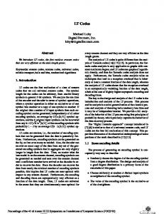
In general, there is a strong relation between the quantities in (4) through (8) and the parameters defined in section II-C for the BEC decoder. They are essentially information based continuous counterparts of the discrete symbol based versions from the BEC. Table I lists an overview of the analogies. The contributions from a single input symbol to the BIAWGN parameters are illustrated in Fig. 2, where the entropy
1
IPℓ−1 = IPℓ � ′� H Ziℓ ℓ IQ ℓ−1 IR
� ′ � H Ziℓ +
ℓ IR
� ℓ−1
H Zi
H Ziℓ
ILℓ−1 = ILℓ
ℓ IA
� 0 0
1
2
3
4
5
6
7
8
LLR
Fig. 2. Entropy as a function of LLR for an input symbol i. The contribution to the defined quantities are annotated, assuming that the symbol has not passed a new message, but received new information from its neighbors. TABLE I A NALOGIES BETWEEN BEC PARAMETERS AND BIAWGN PARAMETERS . BEC L: The number of unprocessed input symbols Q(L): The number of released symbols in the k−L’th decoding step A(L): The number of symbols added to the ripple in the k − L’th decoding step R(L): The size, in symbols, of the ripple after k − L decoding steps
BIAWGN ℓ : The amount of unprocessed IL information among input symbols after ℓ decoding rounds ℓ : The amount of released inIQ formation in the ℓ’th decoding round ℓ : The amount of information IA added to the ripple in the ℓ’th decoding round ℓ : The size of the informaIR tion ripple after ℓ decoding rounds
of a single input symbol has been plotted as a function of its LLR. Due to the convexity of the entropy function (except at ℓ−1 ℓ ℓ very low LLR), we have IA < IQ when IR > 0, which indicates loss of information. This is analogous to the risk of redundancy for nonzero ripple in the BEC. B. First Moment of Information Ripple One particularly interesting quantity in a ripple-based design is the expected amount of released information from an output symbol of degree d as a function of the amount of unprocessed information. This is key since it expresses the universal connection between the degree distribution, which is the design parameter, and the rate of recovery of new information during the decoding process. It was derived in [1] for the BEC and is repeated below for convenience of further discussion. q(1, k) = 1, q(d, L) =
d(d − 1)L
Qd−3 j=0
Qd−1 j=0
(k − (L + 1) − j) (k − j)
,
for d = 2, ..., k, and L = k − d + 1, ..., 1,
q(d, L) = 0, for all other d and L,
(9)
where q(d, L) is the probability that an encoded symbol of degree d is released when L out of k input symbols remain unprocessed. Deriving the BIAWGN channel equivalent to (9) is outside the scope of this paper. However, we can easily obtain an understanding of its behavior by simulating an LT code in
SØRENSEN et al.: RIPPLE DESIGN OF LT CODES FOR BIAWGN CHANNELS
5
0.1
0.04
Iq (d, IL )
0.03
Normalized Frequency
d=2 d=3 d=4 BEC Theory
0.02
0.01
0.08 0.06 0.04 0.02 0
−0.5
−0.4
−0.3
−0.2
−0.1
0 ℓ IA ℓ IQ
0
60
50
40
30
20
10
0.1
−
0.2
0.3
0.4
0.5
A Q
0
IL
Fig. 3. Comparison of simulated IQ as a function of d and quantized IL and corresponding curves from (9).
ℓ /I ℓ from AWGN Fig. 4. Histogram of the difference between simulated IA Q channel and theoretic A(L)/Q(L) from the BEC.
result is ℓ a BIAWGN channel and logging IQ versus ILℓ for different ℓ degrees. By the definitions of IQ and ILℓ , their relationship at a certain value of d is the BIAWGN equivalent of (9). In order to compare with (9), we quantize ILℓ to integer values {0, 1, ..., k}, such that we have a vector of length k + 1, in ℓ for all ℓ where which the i’th element represents the sum of IQ ℓ |IL − (i − 1)| < 0.5. When normalizing this vector, such that it sums to one, an element will represent the fraction of the released information, which is released when IL bits remain unprocessed. This is denoted as Iq (d, IL ) for output symbols of degree d and is defined as
Iq (d, IL ) =
X
ℓ IQ
ℓ −I | c1 IL for IL ≤
= IL ,
In order to achieve the target ripple evolution in (12), we must find a degree distribution, which provides released information distributed correctly. Following our specification L = of the target ripple at integer ILℓ , we introduce IA P ℓ ℓ I , which is a quantization of I to integer ℓ A ℓ:|IL −IL | 0 and c2 ≥ 2. Note that, by definition L ≤ IL , hence the of the information ripple, we must have IR need for a cap in the target.
L L IR = IA ,
TABLE II D EGREE DISTRIBUTION EXAMPLE FOR k = 500, c1 = 2.0 AND c2 = 2.6.
When solving (15), we find the vector n Ω(d). Hence, a solution tells us how many bits should be carried by symbols
of the different degrees, in order to achieve the desired ripple evolution. Normalizing the solution vector with n′ provides the degree distribution. However, since the matrix in (15) becomes singular for high k, the proposed ripple evolution can only be achieved for short message lengths. Nonetheless, a ripple evolution close to the target can be achieved with the least-squares nonnegative solution to (15). Table II shows an example of a code with parameters k = 500, c1 = 2.0 and c2 = 2.6. The least-squares solution has an error vector with squared norm 3.3 · 10−8 , which is negligible. V. N UMERICAL R ESULTS In this section, the proposed design Ω(d) is evaluated in comparison to standard LT codes using the Robust Soliton distribution (RSD) and the solutions proposed in [8] (TF) and [2] (Φ(d)). The RSD was first presented in [1] and is the de facto standard for LT codes in the BEC. The performance metric of the first evaluation is the average overhead necessary to reach |Zi | > 20 for all i. The simulations have been performed at γ = {0, 2, 4, 6, 8, 10} dB. A BP decoder with parallel scheduling is applied with a maximum iterations of 100. For every value of γ, the parameters of the RSD, c and δ, and the parameters of Ω(d), c1 and c2 , are optimized numerically. These optimizations show that the RSD is very sensitive to variations in γ, whereas Ω(d) is much more robust in this sense. Table III shows optimal parameter values at k = 1000 for the two degree distributions. The average overhead as a function of γ is shown in Fig. 5 for the codes along with the capacity of the BIAWGN channel. The results are averages of 1000 simulations. The results show that TF and an LT code applying the RSD have similar performance, despite the relatively high message length for TF. They also show that the design proposed in this work has a performance similar to the reference schemes already at a message length of 500. As the message length is increased, the proposed design is able to close a significant part of the gap to capacity observed for the reference schemes.
SØRENSEN et al.: RIPPLE DESIGN OF LT CODES FOR BIAWGN CHANNELS
7
TABLE III O PTIMAL PARAMETER VALUES AT k = 1000. RSD c δ 0.015 0.03 0.020 0.05 0.030 0.20 0.050 0.40 0.060 1.00 0.100 4.00
Ω(d) c1 c2 2.0 2.6 2.0 2.6 2.0 2.8 1.8 2.2 2.2 2.6 2.2 2.8
Ω(d) Φ(d) LT Φ(d) Ra pto r
−2
10 B it error ra te
γ 0 2 4 6 8 10
0
10
−4
10
−6
10
1.6
−8
10 Ω(d) k = 500 Ω(d) k = 2 .00 0 Ω(d) k = 4 .00 0 Ω(d) k = 16.00 0 T F k = 16.00 0 RSD k = 2 .00 0 Sha nno n lim it
1.4
1
1.5
2 O verhead (1 + ǫ)
2.5
3
Fig. 6. Comparison between the proposed design and the work in [2] with respect to bit error rate as a function of overhead. 22
1.3
Avera ge o utput sym bo l deg ree
Avg . overhea d (1 + ǫ)
1.5
1.2
1.1
1
0
2
4
6
8
20 18 Ω(d) RSD Φ(d)
16 14 12
10
γ 10
Fig. 5. Comparison of the evaluated codes with respect to average overhead as a function of SNR.
0
Fig. 7.
Next, we compare Ω(d) with the Raptor code from [2] in terms of bit error rate (BER) as a function of the overhead. The comparison is performed at k = 4000 and γ = 0.2 dB, since the degree distribution presented in [2] is designed for this channel quality. The optimized parameter values for Ω(d) are c1 = 2.2 and c2 = 2.4. The maximum number of allowed iterations in the BP decoder with parallel scheduling is 100 and results are averages of 100.000 simulations. As in [2], we include results for both the Raptor code and the LT code component only. The results are shown in Fig. 6, where it is seen that the proposed design outperforms both the LT code and Raptor code from [2] at lower overheads. Both LT codes have an error floor, which is a well-known drawback of many designs of these codes. It has recently been shown in [21] that by shaping the input symbol degree distribution, the error floor can be mitigated. The problem can also be mitigated through precoding, as is done with Raptor codes. This is evident from Fig. 6. Finally, we also present a comparison of the complexities of the evaluated codes. Parameter values optimized for γ = 0 dB are applied, see Table III. The encoding and decoding complexities are directly related to the average output symbol degree, which is plotted as a function of the message length in Fig. 7. The figure shows that the proposed design exhibits a complexity increase similar to that of the RSD, although with an offset of roughly 4. Hence, the superior performance
2000
4000
6000 8000 10000 M essag e leng th (k)
12000
14000
16000
Comparison of the complexities of the evaluated LT codes.
comes at the price of increased complexity. The average output symbol degree of the design from [2] is independent of k, hence the complexity is linear. This was the design goal of Raptor codes. The price paid is a slight decrease of the code rate due to the precoder, which is also evident from Fig. 6. VI. C ONCLUSIONS We have presented a framework for a ripple-based design of LT codes in BIAWGN channels. This framework builds a bridge between the original work on LT codes for the BEC and noisy channels, which is a major contribution of this paper. Surprisingly, key analytical results, originally derived for the BEC, have been shown to hold in the BIAWGN as well. A design example applying the presented framework has been given. Numerical evaluations show promising results, significantly outperforming a standard LT code with the robust soliton distribution and the turbo fountain from [8], at the price of a minor increase of complexity. The application of the framework is not limited to BIAWGN channels and LT codes. It can readily be extended to any noisy channels and/or related rateless codes, e.g. Raptor codes. R EFERENCES [1] M. Luby, “LT Codes,” in Proc. 2002 IEEE Symposium on Foundations of Computer Science, pp. 271–280.
8
IEEE TRANSACTIONS ON COMMUNICATIONS, ACCEPTED FOR PUBLICATION
[2] O. Etesami and A. Shokrollahi, “Raptor codes on binary memoryless symmetric channels,” IEEE Trans. Inf. Theory, vol. 52, pp. 2033–2051, May 2006. [3] S.-Y. Chung, T. Richardson, and R. Urbanke, “Analysis of sum-product decoding of low-density parity-check codes using a Gaussian approximation,” IEEE Trans. Inf. Theory, vol. 47, pp. 657–670, Feb. 2001. [4] Z. Cheng, J. Castura, and Y. Mao, “On the design of raptor codes for binary-input Gaussian channels,” IEEE Trans. Commun., vol. 57, pp. 3269–3277, Nov. 2009. [5] I. Hussain, M. Xiao, and L. Rasmussen, “LT coded MSK over AWGN channels,” in Proc. 2010 International Symposium on Turbo Codes and Iterative Information Processing, pp. 289–293. [6] P. Pakzad and A. Shokrollahi, “Design principles for raptor codes,” in Proc. 2006 IEEE Information Theory Workshop, pp. 165–169. [7] K. Kasai, D. Declercq, and K. Sakaniwa, “Fountain coding via multiplicatively repeated non-binary ldpc codes,” IEEE Trans. Commun., vol. 60, no. 8, pp. 2077–2083, 2012. [8] H. Jenkac, J. Hagenauer, and T. Mayer, “The turbo-fountain and its application to reliable wireless broadcast,” in Proc. 2005 European Wireless Conference – Next Generation Wireless and Mobile Communications and Services, pp. 1–7. [9] T.-Y. Chen, D. Divsalar, and R. Wesel, “Protograph-based raptor-like LDPC codes with low thresholds,” in Proc. 2012 IEEE International Conference on Communications, pp. 2161–2165. [10] S.-Y. Chung, “On the construction of some capacity-approaching coding schemes,” Ph.D. thesis, Massachusetts Institute of Technology, 2000. [11] J. Sørensen, T. Koike-Akino, P. Orlik, J. Østergaard, and P. Popovski, “Ripple design of lt codes for awgn channel,” in Proc. 2012 IEEE International Symposium on Information Theory, pp. 1757–1761. [12] H. Zhu, G. Zhang, and G. Li, “A novel degree distribution algorithm of LT codes,” in Proc. 2008 IEEE International Conference on Communication Technology, pp. 221–224. [13] G. Maatouk and A. Shokrollahi, “Analysis of the second moment of the LT decoder,” in Proc. 2009 IEEE International Symposium on Information Theory, pp. 2326–2330. [14] S. Sanghavi, “Intermediate performance of rateless codes,” in Proc. 2007 IEEE Information Theory Workshop, pp. 478–482. [15] S. Karande, K. Misra, S. Soltani, and H. Radha, “Design and analysis of generalized LT-codes using colored ripples,” in Proc. 2008 IEEE International Symposium on Information Theory, pp. 2071–2075. [16] J. Sørensen, P. Popovski, and J. Østergaard, “Design and analysis of LT codes with decreasing ripple size,” IEEE Trans. Commun., vol. 60, pp. 3191–3197, Nov. 2012. [17] J. Goldberger and H. Kfir, “Serial schedules for belief-propagation: analysis of convergence time,” IEEE Trans. Inf. Theory, vol. 54, pp. 1316– 1319, Mar. 2008. [18] J. Zhang and M. Fossorier, “Shuffled iterative decoding,” IEEE Trans. Commun., vol. 53, no. 2, pp. 209–213, 2005. [19] E. Sharon, S. Litsyn, and J. Goldberger, “Convergence analysis of serial message-passing schedules for LDPC decoding,” in Proc. 2006 International Symposium on Turbo Codes Related Topics, and 2006 International ITG-Conference on Source and Channel Coding, pp. 1–6. [20] A. Shokrollahi, “Raptor codes,” IEEE Trans. Inf. Theory, vol. 52, pp. 2551–2567, June 2006. [21] I. Hussain, M. Xiao, and L. Rasmussen, “Error floor analysis of LT codes over the additive white Gaussian noise channel,” in Proc. 2011 IEEE Global Telecommunications Conference, pp. 1–5. Jesper H. Sørensen (M’10) received the B.Sc. in electrical engineering in 2007, the M.Sc. (cum laude) with the maximum grade average in 2009 and the Ph.D. in wireless communications in 2012, all from Aalborg University, Denmark. In second half of 2011 he worked as an intern at Mitsubishi Electric Research Laboratories. Since 2012 he has been a postdoctoral researcher at Aalborg University. His work is in the areas of channel coding, multimedia communication and information theory.
Toshiaki Koike-Akino received the B.S. degree in electrical and electronics engineering, M.S. and Ph.D. degrees in communications and computer engineering from Kyoto University in 2002, 2003 and 2005, respectively. Since 2006 he has been a postdoctoral researcher at Harvard University, and concurrently has been a visiting researcher at Mitsubishi Electric Research Laboratories (MERL) since 2010. His research interest includes digital signal processing for cooperative communications. He received the YRP Encouragement Award 2005, the 21st TELECOM System Technology Award, the 2008 Ericsson Young Scientist Award, the IEEE GLOBECOM’08 Best Paper Award in Wireless Communications Symposium, the 24th TELECOM System Technology Encouragement Award, and the IEEE GLOBECOM’09 Best Paper Award in Wireless Communications Symposium. Philip V. Orlik (S’97–M’99) was born in New York, NY in 1972. He received the B.E. degree in 1994 and the M.S. degree in 1997 both from the State University of New York at Stony Brook. In 1999 he earned his Ph.D. in electrical engineering also from SUNY Stony Brook. In 2000 he joined Mitsubishi Electric Research Laboratories Inc. located in Cambridge, MA, where he is currently the Team Leader of the Mobile Systems Group. His primary research focus is on advanced wireless and mobile communications, sensor networks, ad hoc networking and UWB. Other research interests include vehicular/car-tocar communications, mobility modeling, performance analysis, and queuing theory. Jan Østergaard (S’98–M’99–SM’11) received the M.Sc.E.E. from Aalborg University, Aalborg, Denmark, in 1999 and the Ph.D. degree (cum laude) from Delft University of Technology, Delft, The Netherlands, in 2007. From 1999 to 2002, he worked as an R&D Engineer at ETI A/S, Aalborg, Denmark, and from 2002 to 2003, he worked as an R&D Engineer at ETI Inc., Virginia, United States. Between September 2007 and June 2008, he worked as a post-doctoral researcher at The University of Newcastle, NSW, Australia. From June 2008 to March 2011, he worked as a post-doctoral researcher/Assistant Professor at Aalborg University. Since 2011 he has been an Associate Professor at Aalborg University. He has been a visiting researcher at Tel Aviv University, Tel Aviv, Israel, and at Universidad T´ecnica Federico Santa Mar´ıa, Valpara´ıso, Chile. He has received a Danish Independent Research Council’s Young Researcher’s Award and a post-doctoral fellowship from the Danish Research Council for Technology and Production Sciences. Dr. Østergaard is currently an associate editor for EURASIP Journal on Advances in Signal Processing. Petar Popovski (S’97-A’98–M’04–SM’10) received Dipl.-Ing. in electrical engineering (1997) and Magister Ing. in communication engineering (2000) from Sts. Cyril and Methodius University, Skopje, Macedonia, and Ph.D. from Aalborg University, Denmark, in 2004. He is currently a Professor at Aalborg University. He has more than 180 publications in journals, conference proceedings and books and has more than 30 patents and patent applications. He has received the Young Elite Researcher award and the SAPERE AUDE career grant from the Danish Council for Independent Research. He has received six best paper awards, including three from IEEE. Dr. Popovski serves on the editorial board of several journals, including IEEE C OMMUNICATIONS L ETTERS (Senior Editor), IEEE JSAC Cognitive Radio Series, and IEEE T RANSACTIONS ON C OMMUNICATIONS . He is a Steering Committee member for IEEE I NTERNET OF T HINGS J OURNAL and Chair of the ComSoc subcommittee on Smart Grid Communications. His research interests are in the broad area of wireless communication and networking, communication theory and protocol design.