Robust Control of an Induction Motor Drive. Automatic Control. School of
Electrical Engineering. Royal Institute of Technology (KTH). SE-100 44
Stockholm, ...
Robust Control of an Induction Motor Drive Henrik Mosskull
TRITA–EE 2006:008 ISSN 1653-5146 ISBN 91-7178-309-1
Automatic Control School of Electrical Engineering Royal Institute of Technology (KTH) Stockholm, Sweden, 2006
Submitted to the School of Electrical Engineering, Royal Institute of Technology, in partial fulfillment of the requirements for the degree of Doctor of Philosophy.
Copyright © 2006 by Henrik Mosskull
Robust Control of an Induction Motor Drive
Automatic Control School of Electrical Engineering Royal Institute of Technology (KTH) SE-100 44 Stockholm, Sweden
Abstract This thesis considers robust control of an induction motor drive, consisting of an input filter, a voltage source inverter and one or several induction motors in parallel. The motor torque is here controlled by using the method Indirect Self Control (ISC), and power oscillations between the inverter and the input filter are damped by means of a stabilization controller in an outer feedback loop. Closed-loop performance with ISC is analyzed under the assumption of a stiff inverter input voltage. It is shown how parameter errors influence the torque loop and the conclusion is that the motor leakage inductance should not be overestimated, especially not with a large desired control bandwidth. It is also shown that model errors enhance cross coupling, but that the performance is quite insensitive even to large parametric errors. Based on the closed-loop model, expressions for the controller parameters are derived to obtain required stability margins. For design of the stabilization controller to suppress oscillations between the inverter and the input filter, it is shown that the effects of time delays and limited torque (or current) control bandwidth are important and cannot be neglected. From models including these non-ideal properties of the control system, explicit expressions for stabilization controllers to use with ISC as well as field-oriented control (FOC) are derived. This is valuable as stabilization often is designed through costly and time-consuming manual tuning. In the controller design, the trade-off between tight torque control and stability of the DC-link is also explicitly considered. In this way reasonable stability margins are obtained, while minimizing the negative effects on torque control. Stability of the closed-loop drive with the proposed stabilization is validated through realistic hardware-in-the-loop simulations using real control HW and SW. Using models obtained from frequency domain system identification, stability of the non-linear closed-loop drive is verified by combining stability results for linear systems with the small gain theorem for the non-linear model errors. This thesis considers the input filter dynamics in connection with torque control of an induction motor. The key result is a model-based framework for simultaneous treatment of DC-link stability and efficient torque control.
Acknowledgements This work is the result of a collaboration between Bombardier Transportation in Västerås and KTH in Stockholm. I would first of all like to express my gratitude to the people who made this work possible in the first place. These include my supervisor at KTH, Prof. Bo Wahlberg and Peter Oom and Dr. Kent Öhrn at Bombardier Transportation. My technical supervisor at Bombardier Transportation was Johann Galic. Without his experience and deep knowledge of drives, power electronics and control, this work would not have been completed. Thanks for sharing your time and your wisdom, Johann! I would also like to thank Prof. Stefan Östlund for support regarding general issues related to induction motor control and the people introducing me to the subject, Dr. Steffen Richter, Dr. Peter Krafka and Michael Rampe, whom I have had the pleasure to work with. I want to thank Prof. Anders Helmersson for valuable help with numerically solving the LMIs in Chapter 9 and Prof. Elling Jacobsen for teaching me robust multivariable feedback control. Eva Sandberg was kind to help me with the layout in Microsoft Word and Karin Karlsson-Eklund guided me through the administrative routines at KTH. This work was partly supported by The Swedish Science Foundation, which is gratefully acknowledged. Finally, I would like to thank my family for support and encouragement.
Contents 1
Introduction .........................................................................1 1.1 Background ..................................................................................... 2 1.2 Induction Motor Drive .................................................................... 3 1.3 Torque Control of an Induction Motor............................................ 6 1.3.1 Field-Oriented Control (FOC) ............................................. 6 1.3.2 Direct Torque Control (DTC) .............................................. 7 1.4 DC-Link Stability.......................................................................... 10 1.4.1 Constant Power Operation ................................................. 10 1.4.2 Stabilization with Perfect Torque Control ......................... 12 1.4.3 Improved Stabilization Structure ....................................... 14 1.4.4 Improved Modeling for Stabilization Synthesis ................ 16 1.4.5 Input Filter Oscillations with DC-DC Converters ............. 18 1.5 Notation and Nomenclature .......................................................... 19 1.6 Outline and Contributions ............................................................. 20
2
Voltage Source Inverter ....................................................25 2.1 Three-Phase Voltage Source Inverter ........................................... 25 2.2 Modulation.................................................................................... 28 2.2.1 Pulse Width Modulation .................................................... 29 2.2.2 Six-Step Operation............................................................. 31
3
Induction Motor ................................................................35 3.1 Physical Description ..................................................................... 35 3.2 Equivalent Circuit Diagrams......................................................... 37 3.3 Inverse Gamma Model.................................................................. 39 3.3.1 Stator Coordinates ............................................................. 39 3.3.2 Synchronous and Rotor Flux Coordinates ......................... 40 3.3.3 Current Control .................................................................. 42 3.4 Gamma Model .............................................................................. 43 3.4.1 Stator Coordinates ............................................................. 43
viii
Contents
3.4.2 Slip Frequency Control...................................................... 44
4
Controllability Analysis ....................................................47 4.1 Input Constraints ........................................................................... 48 4.2 Polar Representation ..................................................................... 48 4.3 Poles and Zeros ............................................................................. 51 4.4 Relative Gain Array (RGA) .......................................................... 52 4.5 Scaling .......................................................................................... 53 4.6 Singular Values ............................................................................. 54 4.7 Flux Control Robustness ............................................................... 56 4.8 Time Delays .................................................................................. 57 4.9 Limitations Imposed by Input Constraints .................................... 57 4.9.1 Disturbance Rejection........................................................ 58 4.9.2 Reference Tracking............................................................ 58 4.10 Singular Values Revisited ............................................................. 59 4.11 Summary ....................................................................................... 62
5
Field-Oriented Control .....................................................65 5.1 Current Control with Active Damping.......................................... 65 5.2 Rotor Flux Estimation ................................................................... 71 5.3 Closed-Loop Torque Dynamics .................................................... 73
6
Indirect Self Control .........................................................77 6.1 Discrete-Time ISC ........................................................................ 77 6.1.1 Control Law ....................................................................... 78 6.1.2 Prediction........................................................................... 81 6.1.3 Average Torque ................................................................. 82 6.2 Continuous-Time ISC ................................................................... 82 6.2.1 Control Law ....................................................................... 82 6.2.2 Prediction........................................................................... 84 6.2.3 Average Torque ................................................................. 85 6.3 Closed-Loop System ..................................................................... 85 6.3.1 Model without Time Delays .............................................. 86
Contents
ix
6.3.2 Model with Time Delays and Disturbance Rejection ........ 89 6.4 Controller Tuning.......................................................................... 91 6.4.1 Zero - Pole Cancellation .................................................... 93 6.4.2 Loop Shaping..................................................................... 94 6.4.3 Gain Scheduling................................................................. 95 6.5 Simulations ................................................................................... 96 6.6 Summary ....................................................................................... 98
7
ISC with Observer.............................................................99 7.1 Torque and Stator Flux Estimation ............................................... 99 7.2 Full-Order Observer .................................................................... 100 7.2.1 Observer Equations.......................................................... 101 7.2.2 Parameter Variations........................................................ 105 7.2.3 Steady State Stator Flux Estimation ................................ 106 7.2.4 Steady-State Torque Estimation ...................................... 108 7.3 Model of Closed-Loop System with Observer............................ 111 7.3.1 Model with Zero Observer Gain ...................................... 112 7.3.2 Model with Non-Zero Observer Gain.............................. 116 7.4 Summary ..................................................................................... 118
8
Sensitivity and Robustness Analysis ..............................119 8.1 Performance Requirements ......................................................... 120 8.1.1 Sensitivity Requirements ................................................. 120 8.1.2 Input Requirements.......................................................... 121 8.2 Perfect Field Orientation ............................................................. 122 8.3 Flux Estimation with Open-Loop Observer ................................ 127 8.3.1 Rotor Parameter Errors .................................................... 128 8.3.2 Additional Parameter Variations...................................... 130 8.3.3 Estimated Currents for Torque Estimation ...................... 133 8.4 Flux Estimation with Closed-Loop Observer.............................. 134 8.5 Non-Parametric Uncertainty ....................................................... 135 8.5.1 Structured Singular Value................................................ 136 8.5.2 Uncertainty Description ................................................... 137 8.5.3 Model for Controller Evaluation...................................... 138 8.5.4 Controller Evaluation....................................................... 141
x
Contents
8.5.5 Simulations ...................................................................... 144 8.6 Summary ..................................................................................... 145
9
Linear Controller Design ................................................147 9.1 µ-Synthesis.................................................................................. 148 9.2 LFT Controller ............................................................................ 150 9.2.1 Linear Process Model ...................................................... 152 9.2.2 Extracting the Stator Frequency....................................... 154 9.2.3 Model for Controller Synthesis........................................ 154 9.2.4 Results ............................................................................. 155 9.3 Summary ..................................................................................... 157
10 DC-Link Stability ............................................................159 10.1 Linear Model of the Drive........................................................... 160 10.1.1 Indirect Self Control (ISC) .............................................. 160 10.1.2 Field-Oriented Control (FOC) ......................................... 161 10.1.3 Feedback Representation of the Drive ............................. 162 10.2 Stability Analysis ........................................................................ 164 10.2.1 Unstable Examples Revisited .......................................... 164 10.2.2 Normalization of Coupling Vector .................................. 168 10.2.3 Stability and Performance Requirements......................... 169 10.3 Alternative Stabilization Methods............................................... 169 10.3.1 Current Reference Modification ...................................... 170 10.3.2 Stator Voltage Modification ............................................ 171 10.3.3 Stator Frequency Modification ........................................ 172 10.3.4 Modification of Average Filter ........................................ 173 10.4 Stabilization Controller Design................................................... 174 10.4.1 Design for Maximum Stability Margin............................ 175 10.4.2 Improved Disturbance Rejection ..................................... 176 10.4.3 Approximation of Gc-1 ..................................................... 179 10.4.4 Practical Stabilization Controllers ................................... 181 10.5 Summary ..................................................................................... 183
11 Verification of Stability Margins from Measurements .185 11.1 Stability and Robustness Analysis .............................................. 186 11.1.1 Input-Output Stability ...................................................... 187 11.1.2 Stability Analysis............................................................. 187
Contents
xi
11.1.3 Robustness ....................................................................... 189 11.2 Implementation ........................................................................... 191 11.2.1 Pulse Patterns................................................................... 191 11.2.2 Stabilization and Torque Controllers ............................... 194 11.3 Linear Stability Analysis............................................................. 194 11.3.1 Identification of Inverter Input Admittance ..................... 195 11.3.2 Coasting ........................................................................... 196 11.3.3 Driving............................................................................. 199 11.3.4 Braking ............................................................................ 201 11.4 Linearization Errors .................................................................... 203 11.4.1 Linearization Errors ......................................................... 203 11.4.2 Experimental Result......................................................... 205 11.4.3 Power Iterations ............................................................... 207 11.5 Summary ..................................................................................... 208
12 Summary and Suggestions for Future Work................211 12.1 Summary ..................................................................................... 211 12.2 Future Work ................................................................................ 214
A
Drive Data ........................................................................217 Drive Data Set 1 .................................................................................. 217 Drive Data Set 2 .................................................................................. 217 Motor Parameters........................................................................ 218 Input Filter Data .......................................................................... 218 Tractive Effort............................................................................. 218
B
Closed-Loop Equations...................................................221 Real-Valued Space Vector Representation.......................................... 221 Closed-Loop System without Time Delays ......................................... 222 Non-Linear Equations of Decoupling ......................................... 222 Steady State Relations................................................................. 223 Linearization of Decoupling ....................................................... 224 Transfer Function Representation ............................................... 226 Linearization of Feedback Controllers........................................ 229 Closed-Loop Equations............................................................... 229 Closed-Loop System with Time Delays .............................................. 233
xii
Contents
Linear Model of Prediction ......................................................... 233 Closed-Loop Equations............................................................... 235
C
Steady State Analysis ......................................................237 Stator Flux Estimation Error................................................................ 237 Torque Estimation Error...................................................................... 239
D
Non-Zero Observer Gain ................................................245
E
Space Vectors ...................................................................249
F
Singular Values with Space Vector Representation.....253
Bibliography............................................................................257
Chapter 1
Introduction This thesis treats robust control of an induction motor drive used for DC traction applications. An induction motor drive consists of an input filter, a voltage source inverter and one or several induction motors in parallel. The input filter, which is directly connected to the line, is needed as an energy reservoir and to suppress switching harmonics generated by the inverter. During control design, the input filter is often neglected. To compensate for a varying filter voltage in a practical application, the inverter modulation ratio is modified to ensure that the desired stator voltages always are applied to the motors. However, with a resonant input filter, this kind of suppression of voltage variations may lead to power oscillations between the inverter and the input filter. There is hence a trade-off between efficient disturbance rejection and stability of the drive. In this thesis, the problem of ensuring robust torque control of a drive including input filter is studied in detail. In a traction application, the operating conditions, such as speed, load and temperature, vary over a wide range. Furthermore, the electrical environment of the drive depends on the number of surrounding trains and feeder stations, and the distances between them. In practice all process signals needed for parameter adaptation are not feasibly measurable and all parameter variations are not practical to implement. To always guarantee satisfying performance, robust control algorithms are therefore required. Section 1.1 motivates the need of further research in the field and Section 1.2 presents induction motor drives in more detail. Commonly used torque control methods are briefly discussed in Section 1.3, whereas a fairly detailed introduction to the problem of power oscillations between the inverter and input filter is given in Section 1.4. Section 1.5 then introduces notation and nomenclature, while Section 1.6 gives the outline of the thesis and highlights the major contributions.
2
1.1
Introduction
Background
The behavior of an induction motor is accurately described by well known mathematical models. Still, for practical use, the motor parameters must be estimated and correctly adapted to the operating conditions. As highperformance control methods are model based, the closed-loop performance is influenced by the accuracy of the estimated motor parameter. Here it is valuable to know which motor parameters are most critical and how model errors affect performance. These issues have been explored for the so-called classical field-oriented control or vector control. However, for the control scheme Indirect Self Control (ISC), on which this thesis focuses, few results have been published in the literature. This thesis aims at filling this gap. Traditionally, torque control of an induction motor drive is designed while neglecting the dynamics of the input filter. The effects of a varying DC-link voltage, i.e., the input voltage to the inverter, are then counteracted by adapting the modulation ratio of the inverter. This suppression of DC-link voltage variations gives the inverter a negative-resistance behavior as seen from the DC link. In connection with a poorly damped input filter, this property of the controlled inverter may destabilize the drive. Such stability problems are not unique for induction motor drives but have been treated also for other kinds of switching converters, e.g. DC-DC converters. For these applications, the stability problem has been solved by adding resistance to the input filter. However, for high power drives, this solution is not feasible due to the large additional power losses. Here the problem has instead been solved by adding fictitious resistance. The behavior of the inverter is then changed through control to emulate an increased resistance. In a torque controlled drive, this may be achieved by modifying the torque reference as a function of variations in the DC-link voltage. Explicit schemes to do this have been derived using simple models of the controlled inverter. However, the approximations made during design of stabilization have turned out to be too crude to always stabilize a drive in practice. To handle these cases, more general stabilization structures have been introduced. Tuning of the stabilization functionality is, however, usually left to the user. Practical experience shows that stabilization needs to be adapted to the operating point, which in practice often leads to a non-negligible amount of manual tuning. The goal of this thesis is to find explicit ways of optimizing the design of DClink stabilization. It is also the intention to examine different approaches for stabilization regarding performance and implementation issues. This area of research is relatively little explored. Much effort in recent research has been spent on speed sensorless and nonlinear control of induction motors. For the
Introduction
3
induction motor drives studied in this thesis, we assume that speed sensors are present, which usually is the case in a traction application.
1.2
Induction Motor Drive
The three-phase induction motor was invented already in the 19th century. Compared to DC motors, induction motors have higher power densities and are mechanically more robust, which make them the ideal motor in many applications. On the other hand, they require AC power supplies and more sophisticated control. First with the invention of field-oriented control (or vector control) in the late 1960’s, [7], [28], control of an induction motor could be compared to that of a separately excited DC motor. The need of advanced power electronics further delayed the widespread use of induction motors in industrial and traction applications till the 1980’s. Today, however, squirrel-cage induction motors fed voltage source inverters (VSI) is standard in traction applications [75]. A typical DC propulsion system in an electric train may therefore be depicted as in Figure 1-1, where the induction motor drive is connected to the DC supply voltage E(t) either via an overhead line or a third rail. The torque generated at the motor shaft is denoted T(t) in Figure 1-1 and the motor speed is represented by ωm(t). id
DC
+
+
E
Ud
-
-
Voltage Source Inverter
Motor
ωm, T
Figure 1-1: DC propulsion system in a traction application.
Each inverter feeds one or several induction motors in parallel and power can flow in both directions, i.e., either from the electric power supply to the motors or vice versa. This way energy generated by braking trains can be used to feed trains that consume power. Especially in a metro system with frequent accelerations and decelerations, the possibility of regeneration generates large power savings. If the line is not receptive, the braking energy is dissipated in a braking resistance, which not is shown in Figure 1-1. An example of a metro with overhead DC voltage supply is shown in Figure 1-2.
4
Introduction
Figure 1-2: Guangzhou metro.
The three-phase AC voltage for the induction motors is generated from a DC voltage through the voltage source inverter in Figure 1-1. The DC-link voltage Ud(t) is fed by the supply voltage E(t) via an input filter, composed of a capacitor with capacitance C and an inductor with inductance L and resistance R. The capacitor is an energy reservoir for the VSI, whereas the inductor is needed to give appropriate suppression of high frequency harmonics generated by the inverter. By explicitly showing the resistance, the induction motor drive in Figure 1-1 can be represented as in Figure 1-3. Actually, the values of R and L in Figure 1-3 should also include resistance and inductance of the overhead line. This will, however, be neglected in this thesis as the inductance of the overhead line normally is small compared to the filter inductance.
Figure 1-3: Model of an induction motor drive.
Introduction
5
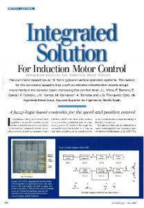
In traction applications, space and weight constraints tend to keep the capacitance C of the input filter relatively small. Moreover, to meet regulations on harmonics suppression, or to assure a certain required input impedance of the drive, the inductance L has to be relatively large. In combination with a small resistance R to keep the power losses acceptable, the resulting input filters get poorly damped with high resonance peaks at the frequency ω0 = 1/√(LC). This is illustrated in Figure 1-4, showing the Bode plot of the transfer function from DC-link current id(t) to line current i(t), which is given by the following equation
i (t ) =
1 id ( t ) . p 2 CL + pCR + 1
(1.1)
Here p is the differential operator and the filter data are taken from Appendix A (input filter with 35.6 Hz resonance frequency). The large resonance peak is hence a consequence of a desired small gain of the filter at high frequencies to suppress switching frequency harmonics. To quantify the damping properties of the input filter, we use the damping factor ζ, which is defined by
ζ =
1 C R . 2 L
(1.2)
Magnitude [abs]
The damping factor for the filter used to generate Figure 1-4 is only 0.02. 10 10 10
Bode Diagram
2
0
-2
-4
10 -1 10
10
0
10
1
10
2
10
3
Phase [deg]
0 -90 -180 -1 10
10
0
1
10 Frequency [Hz]
10
2
10
Figure 1-4: Bode plot of input filter transfer function.
3
6
1.3
Introduction
Torque Control of an Induction Motor
The schematically shown controller in Figure 1-3 controls the operation of the inverter through the coupling vector k(t). Based on measured motor and DClink quantities, the coupling vector is determined to make the motor torque follow a reference, which is denoted by Tref in Figure 1-3. Given that the induction motor is a non-linear multi-input multi-output (MIMO) system with varying parameters, control of these systems is a challenging task that has received rather much attention in the literature over the last decades, see e.g. [11], [68], [83]. In most of these publications, the influence of the power supply is neglected. The inverter is consequently assumed to be connected to a stiff DC-link voltage, which is assumed to be independent of the consumed power. The controlled drive may then be represented by the block diagram in Figure 1-5, where the torque is influenced by the reference signal via the system Gc and through a disturbance in the DC-link voltage through a transfer function Gd. The influence of the motor speed is not explicitly shown in the figure as we often will consider the speed to be constant in this thesis. In traction applications the speed is normally slowly varying due the large mass of a train. (Practical experience also shows no indications of increased stability problems during slippery conditions). Actually, also the flux of the motor will be regulated although this is not explicitly shown in Figure 1-5.
Figure 1-5: Model of a controlled induction motor. Here the dynamics of the input filter are not considered.
1.3.1 Field-Oriented Control (FOC) A major breakthrough in the area of induction motor control was taken with the invention of field-oriented control (FOC) or vector control in the late 1960s. Until then, induction motors had been controlled using so called scalar control methods, like the volt-hertz control. Here the magnitude and frequency of the stator voltage are determined from steady-state properties of the motor, which leads to poor dynamic performance. FOC, on the other hand, uses a vector model of the drive that is valid also during transients, which facilitates
Introduction
7
faster control. The idea with field orientation is to mimic control of DC motors also for induction motors. To accomplish this, the motor equations are described in a coordinate system oriented to the (rotor) flux in the motor. The torque and flux can then be controlled through different components of the stator current. In the rotating coordinate system, all motor quantities are constant at steady state and PI controllers can hence be used to ensure zero steady-state errors. It has later been shown that the classical field-oriented controller can be interpreted as asymptotic exact linearization [50]. Fieldoriented control was developed by a research group lead by Prof. Werner Leonard in Brauschweig, Germany and the concept was initially published in [7] and [28]. See also the well-known book on control of electrical drives by Leonard [42]. Closed-loop stability and performance achived with fieldoriented control have rigorously been treated in a number of papers, see for example [5] and [64]. Selection of controller parameters has been discussed in for example [24], and design of flux estimators in [25]. Recently, much research effort has been spent on using FOC without speed sensors. Basics of field-oriented control will briefly be described in Chapter 5. As explained above, the effect of the power supply (including input filter) is often neglected in connection with induction motor control. In cases where the input filter actually is considered, such as in [3], [16] and [27], variations in the DClink voltage are assumed to be perfectly compensated for. Due to inevitable time delays, perfect cancellation of the influence of a varying DC-link voltage is never possible in practice. In Chapter 5 time delays are considered and an expression for the transfer function Gd in Figure 1-5 is derived. The influence of disturbances in the DC-link voltage on the torque is important when studying DC-link stability, which is done in Chapter 10 and Chapter 11.
1.3.2 Direct Torque Control (DTC) In parallel to the development of FOC, a different class of controllers for induction motors, the so called Direct Torque Control (DTC) methods, emerged in the 1980s. The two classical DTC schemes are the methods invented by Takahashi [82] and Depenbrock [18]. In principle, these methods keep the stator flux space vector on a pre-defined track and control the torque by varying the speed of the flux along the track. Hence, the behavior of the motor is controlled via the stator flux and not the stator current as with FOC. With the method by Takahashi, the stator flux track is circular, whereas a hexagonal track is used with Direct Self Control (DSC), i.e., the method suggested in [18]. The speed of the flux vector along the track is affected by using so called zero vectors (which result in zero stator voltage) and the
8
Introduction
insertion of these vectors is controlled though a torque hysteresis controller. If the speed of the stator flux space vector along the track is larger than the speed of the rotor flux, then the load angle (the angle between the fluxes) increases, which implies that also the torque increases. When the torque reaches an upper hysteresis threshold, a zero vector is applied and the stator flux comes to a halt. The load angle then decreases and the torque eventually reaches a lower hysteresis threshold, where the stator flux is released along the track again. The DSC is illustrated in Figure 1-6, where the zero voltages are marked with dots.
Figure 1-6: Illustration of the operation of the DTC control method DSC, where Ψs represents the stator flux and Ψr the rotor flux of the induction motor. The torque of the induction motor depends on the load angle δ. The dots on the hexagon represent the locations of so-called zero vectors. Here the stator flux space vector rests and as the rotor flux still rotates, the load angle and hence also the torque decreases. When the torque reaches a lower threshold, the zero vector is removed and the stator flux starts moving and the load angle and torque increases. As the torque reaches an upper threshold, a zero voltage in inserted and the stator flux comes to a halt.
Advantages with these types of hysteresis algorithms are simple implementation and excellent dynamic performance also with low switching frequencies. The DSC therefore has successfully been used in high power traction applications, using fairly slowly switching Gate Turn-Off Thyristors (GTOs) [74], [77]. At low speeds, small stator voltages are required, which means that short voltage pulses need to be generated. With DSC, the voltage pulses between two zero vectors (along one hexagon side) are generated by switchings in one phase only. The duration of such pulses are therefore lower
Introduction
9
limited by the so-called minimum on time, i.e., the shortest time between two switchings of a GTO, which is in the range of 150 µs [30]. This lower stator voltage limit is a restriction of DSC, which stimulated the development of the method Indirect Self Control (ISC) as a low-speed support for DSC [30], [33], [34], [49]. With ISC, short voltage pulses are generated by switchings in different phases and the duration of the pulses are no longer lower limited by the minimum on times. Whereas the DSC directly generates the switching commands for the power semiconductors, the ISC generates the switching commands indirectly via a stator voltage reference. This reference then corresponds to an average stator voltage to be applied during a pulse period and is separately converted to switching commands by a modulator. To use a modulator separate from the controller has the benefit that requirements on for example the switching frequency and the generated harmonics can be more easily and directly addressed. In traction applications, the harmonics generated by the drive must be predictable as they may disturb the signaling system and hence in the end cause accidents. This is a further reason why ISC with a PWM modulator may be preferred over DSC. Although the term DTC often is associated with hysteresis methods, we will here classify also ISC as a DTC method. This route is followed also in the survey on DTC schemes given in [14], where control methods operating with closed torque loops without current controllers are referred to as DTC methods. ISC hence differs from the classical FOC methods due to the absence of explicit current controllers, but also in that the ISC is oriented to the stator flux, rather than to the rotor flux. As stator flux estimation is less parameter dependent compared to rotor flux estimation [91], stator flux orientation is often regarded as less sensitive to parameter errors compared to rotor flux orientation. However, relatively few results on performance of ISC with model errors have been published in the literature. This thesis aims at filling this gap by performing a detailed analysis of the closed-loop performance with ISC. In Chapter 6 the closed-loop equations are derived when applying the ISC to an induction motor. These equations are then used to derive expressions for the controller parameters to achieve certain performance requirements. In Chapter 7 and Chapter 8 stator flux estimation and the effects of model errors on steady-state as well as dynamic performance are considered. Remark: In [66] a version of DSC is presented where the switchings are determined through hybrid control techniques. The focus here is to minimize the torque ripple, while keeping the switching frequency as low as possible. No emphasis is put on generating predictable switching frequency harmonics.
10
1.4
Introduction
DC-Link Stability
In a traction application, where a small capacitor of the input filter is preferred due to space and weight constraints, the assumption of an ideal power supply for the inverter is no longer valid. Here the DC-link voltage is not independent of the generated torque and power may start to oscillate between the inverter and the poorly damped input filter. Note that this holds even if the internal torque feedback loop, represented by the blocks Gc and Gd in Figure 1-5, is stable. Such problems have been analyzed for open-loop control of induction motors in [1] and [43]. The practically more interesting case with closed-loop torque control is discussed in e.g. [3], [16], [27], [35], [80] and [86]. The analysis is however constrained by the assumption of perfect rejection of DClink voltage variations, which implies constant power operation. This is never achieved in practice, but the assumption of constant power operation makes it possible to simply understand the stability problems from an electric-circuit point of view. The simple circuit model also naturally leads to the ideas for stabilization of the drive suggested in the literature. In Subsection 1.4.1 we will review the results achieved with the constant power assumption. A similar treatment is found in [3]. We also present an example of stabilization in Subsection 1.4.2, which, under the assumption of perfect torque control (disturbance rejection and reference tracking), would stabilize the drive at all operating points. However, as shown by two examples in Subsection 1.4.3, the simplifying assumptions of perfect control may be too optimistic in a practice. These examples then motivate the use of a more flexible stabilization structure. For proper synthesis of this stabilization scheme, an improved model of the drive is suggested in Subsection 1.4.4.
1.4.1 Constant Power Operation Often the switching commands to the inverter are modified to counteract for variations in the DC-link voltage. Ideally, this compensation is perfect and the stator voltages become completely independent of the DC-link voltage. This will be referred to as perfect disturbance rejection and means that the DC-link voltage has no effect on the power, i.e., the product P(t) = Ud(t)id(t) is assumed to be constant. By differentiating the expression for the constant power we get ∆id ( t ) = −
id0 P ∆U d ( t ) = − 02 ∆U d ( t ) , U d0 U d0 N Y
(1.3)
Introduction
11
where subscripts 0 denote steady-state operating point values. Under the assumption of constant power operation, Equation (1.3) hence forms a linear model of the inverter in Figure 1-3 as seen from the DC link, where Y is the input admittance of the inverter. By defining the corresponding equivalent inverter resistance Rinv as the inverse of Y in (1.3), the drive in Figure 1-3 may be modeled by the simple electric circuit in Figure 1-7. L +
id
R
+
E
Ud
C
-
Rinv
-
Figure 1-7: Linear model of the induction motor drive under the assumption of perfect disturbance rejection (constant power operation). Here the voltage source inverter is modeled by an equivalent resistance Rinv.
As a consequence of the constant power assumption, the equivalent resistance is negative at positive power, see (1.3). This follows as for example a decrease of DC-link voltage must result in an increase of DC-link current to keep the product of DC-link voltage and DC-link current constant. An increased current means that the voltage is further decreased and we intuitively realize that a negative resistance may be bad for stability. That this is indeed the case can be established more rigorously by examining the damping factor ζdrive of the circuit in Figure 1-7, i.e., 1
1 2
ζ drive = (1 + YR ) 2 ζ + Y −
L C
1 L , ≈ ζ + Y 2 C
(1.4)
where ζ is the damping factor of the input filter, see (1.2). From the definition of the admittance in (1.3), it follows that Y is proportional to –P0. The expression for ζdrive in (1.4) then gives that positive operating point power leads to decreased damping of the drive, whereas negative power increases damping. For the drive to be stable, the damping factor ζdrive must be positive, which through (1.3) and (1.4) can be stated in terms of the operating point power as P0 ≤
RC 2 U d0 . L
(1.5)
For the drive with input filter with 35.6 Hz resonance frequency defined in Appendix A, the stability condition (1.5) is only satisfied for powers less than
12
Introduction
10% of nominal power. Hence, these kinds of stability problems need to be considered for practical operation of the drive. Remark: From the characteristic polynomial of the circuit in Figure 1-7, it follows that besides condition (1.5), also the following relation must be satisfied for stability P0 ≤
U d02 . R
(1.6)
The additional condition (1.6) is, however, usually fulfilled in a practical application and (1.5) is the critical limitation. Remark: In trains with AC voltage supply, the DC-link voltage is controlled by a line converter. DC-link instability is therefore less of a problem in AC traction applications compared to DC applications.
1.4.2 Stabilization with Perfect Torque Control Under the assumption of constant power operation, we showed that the inverter in Figure 1-3 simply can be modeled as a resistance. At positive power, this equivalent resistance is negative and for powers larger than the limit in (1.5) the drive becomes unstable. To solve these kinds of problems, the DC-link voltage could be stabilized by additional power electronics, as proposed in [17] or by adding resistance to the input filter as discussed for DC-DC converters in [21]. An alternative, which neither requires extra hardware nor increases power losses, is to modify the input impedance of the inverter. From the expression for the damping factor ζdrive in (1.4), it seems natural to improve damping by making the inverter act like a positive resistance (positive admittance), instead of a negative, as discussed in [3], [16] and [58]. This means that e.g. a decrease in DC-link voltage should result also in a decrease of DC-link current, not an increase as with constant power operation. One way to force this behavior is to modify the torque reference of the drive as suggested in [35] and [80], i.e., U ( t ) ρ d Tref′ ( t ) , P0 ≥ 0 U d0 Tref ( t ) = ρ U d0 Tref′ ( t ) , P0 < 0, U d ( t )
(1.7)
Introduction
13
where T’ref is an external torque reference and P0 = T0ωm0. The parameter ρ in (1.7) is set to either one or two, referred to as linear and quadratic stabilization, respectively. In braking ρ could also be set to zero, which turns stabilization off. Around an operating point with positive power, the DC-link current is increased by an increase in torque at positive speed and by a decrease of torque at negative speed. The opposite holds at negative operating point power. We then realize that with torque reference modification according to (1.7), an increase in DC-link voltage should also result in an increase of DC-link current (and vice versa), which hence should make the inverter behave like a positive resistance. To analytically evaluate the effect of the torque reference modification (1.7), we use the following power balance approximation
id ( t ) U d ( t ) = T ( t ) ωm ( t ) ,
(1.8)
which is valid if power losses of the inverter and motor are neglected. (In case of more than one motor fed in parallel by the inverter, the torque in (1.8) corresponds to the total torque of the drive.) Apart from perfect disturbance rejection, we also assume perfect reference tracking, i.e., T(t) = Tref(t), and insert the stabilization expression (1.7) into the power balance equation (1.8). The relation between the DC-link current and DC-link voltage can then be linearized and the inverter can be modeled by (cf. Figure 1-7)
Rinv
U d02 , P0 ≥ 0 ( ρ − 1) P0 = 2 U d0 , P0 < 0. ( ρ + 1) P 0
(1.9)
For ρ = 1 the equivalent resistance Rinv with positive power is infinite and consequently the DC-link current is unaffected by variations in the DC-link voltage. With ρ = 2, the inverter behaves like a positive resistance, which improves the damping of the drive (compared to the input filter). In braking the equivalent resistance is positive for both choices of ρ (actually the equivalent resistance is positive also without stabilization, i.e., with ρ = 0). Note that with the torque reference modification (1.7), the power consumed (or generated) by the inverter is no longer constant but is affected by variations in the DC-link voltage. This means that the stabilization scheme to some extent worsen disturbance rejection. Also the effective torque dynamics are effected (slowed down) by the stabilization as a change in the external torque reference results in a disturbance in the DC-link, which is counteracted
14
Introduction
by modifying the internal torque reference through (1.7). In general, stabilization therefore is a trade-off between damping and control performance.
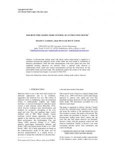
1.4.3 Improved Stabilization Structure In the previous subsection we showed that under the assumption of perfect control (reference tracking as well as disturbance rejection), the stabilization scheme (1.7) would stabilize the drive at all operating points (with all input filters), see (1.9). However, the assumption of perfect torque control never holds in practice, which means that the stability analysis performed above may not be valid. This is also illustrated through the two examples shown in Figure 1-8, where stabilization according to (1.7) with ρ = 2 is applied. In Figure 1-8.A the induction motor drive is simulated at zero torque with the input filter in Appendix A with resonance frequency 18.8 Hz. From the expression for the equivalent resistance (1.9), (or the stability condition (1.5)) this should give a stable system, which however is contradicted by the simulation. In Figure 1-8.B the drive is simulated close to the maximum (pullout) torque with the input filter with resonance frequency 53 Hz in Appendix A. We see that the drive is unstable, although the corresponding equivalent resistance is positive according to (1.9). The simulations are performed at 60% and 50% of nominal speed, where an ISC controller is used giving a control bandwidth of around 40 Hz with a pulse period of 0.91 ms. DC-link voltage
DC-link voltage 3500
1780
3000 2500 Voltage [V]
Voltage [V]
1740
1700
1660
1500 1000 500 0
1620 0
2000
0.5
1
1.5
2 2.5 Time [s]
3
3.5
4
-500 0
0.5
1
1.5
2 2.5 Time [s]
3
3.5
4
Figure 1-8: (A) Simulation showing stability problems of an induction motor drive at zero torque. The simulation is performed at 60% of nominal speed. (B) Unstable example of a drive at maximum (pull-out) torque at 50% of nominal speed.
Hence, we conclude that the simplified analysis failed in predicting stability and that stabilization according to (1.7) does not guarantee a stable drive. The
Introduction
15
stabilization therefore has to be modified. A general drawback with stabilization according to (1.7) is that it does not affect the drive at zero torque. This for example means that this stabilization method cannot be used to stabilize the unstable example at zero torque presented in Figure 1-8.A. Further, the stabilization method (1.7) offers little flexibility as stabilization only can be adjusted via the exponent ρ. We therefore propose to use a more flexible stabilization structure as Tref ( t ) = Tref′ ( t ) + KU d ( t ) ,
(1.10)
where K is a stabilization controller. Note that the DC-link voltage in (1.10) represents deviations from a nominal value and that the stabilization scheme (1.10) allows for stabilization also at zero torque. However, by directly modifying the torque reference as in (1.10), a constant offset in the DC-link voltage would give a constant nonzero torque contribution. This is of course not acceptable and the low frequency contribution must be removed in practice. It may also be advantageous to avoid exiting the torque reference with too high frequencies due to problems with limited control bandwidth (or to avoid aliasing in a digital implementation). The DC-link voltage used in (1.10) is therefore first filtered by a band-pass filter before added to the torque reference. We already here point out that the band-pass filter will be neglected during synthesis of the stabilization controller K, but will be included during controller evaluation. By linearizing the expression in (1.7), this stabilization method can be represented as in (1.10), where the stabilization controller K is given by K=
ρ T0 sgn (ωm0 ) U d0
.
(1.11)
Note that the stabilization controller (1.11) is zero at zero torque and that the effect of the parameter ρ is seen to be a scaling factor for the gain K. Here we may also note that the stabilization method proposed in [86] can be rewritten as T pTC Tref ( t ) = Tref′ ( t ) + k 0 U d (t ) , U d0 pTC + 1 N K
(1.12)
where k ≥ 1 and TC are constants. Stabilization in [86] is only suggested at positive power, which means that K in (1.12) is equivalent to (1.11) with a low-pass filter with time constant TC instead of band-pass filter (that would be
16
Introduction
used together with (1.11) and (1.7) in practice). An advantage with the implementation (1.12), however, is that it is easier to vary the gain of K through the parameter k compared to the exponent ρ in (1.7). Still, the method proposed in [86] offers no stabilization at zero torque as the stabilization controller then is zero. Remark: Stabilization methods similar to (1.10), where variations in the DClink voltage are added to some other reference signal, have been proposed in connection with field-oriented control in [3], [16] and [27]. Here the reference signals are the quadrature stator current reference and the reference stator voltage. In Section 10.3 it will be shown that these schemes are equivalent to stabilization according to (1.10). This means that a specific behavior obtained with one stabilization scheme can be obtained also with the others. It will be shown how to convert the stabilization controllers between the different methods. The detailed treatment of stabilization will therefore be concentrated to the method (1.10).
1.4.4 Improved Modeling for Stabilization Synthesis The task is now to synthesize the stabilization controller K in (1.10) to stabilize the drives at all operating points with a large variety of input filters (including the two cases simulated above). From the results of the previous subsections we realize that for adequate synthesis of the stabilization controller, we need better models of the drive, where the assumption of perfect control is relaxed. We therefore model the controlled induction motor as in Figure 1-5, i.e., T ( t ) = Gc ( p ) Tref ( t ) + Gd ( p ) U d ( t ) ,
(1.13)
where Gc and Gd are transfer functions (we neglect variations in the motor speed, which is considered to be constant). In order to link the AC and DC sides of the inverter in Figure 1-3, we use the power balance equation (1.8). If we consider the speed ωm to be fixed, this equation can be linearized to give id ( t ) =
ωm0 U d0
T (t ) −
T0ωm0 Ud (t ) , U d02
(1.14)
where the quantities in (1.14) hence represent deviations from an operating point.
Introduction
17
The DC-link voltage and the DC-link current are also linked through the input filter in Figure 1-3. As a matter of fact, the DC-link voltage depends on the line voltage and the DC-link current in the following way U d ( t ) = GE ( p ) E ( t ) − Z DC ( p ) id ( t ) ,
(1.15)
where the transfer functions GE(s) and ZDC(s) are given by GE ( s ) =
1 sL + R , Z DC ( s ) = 2 . s CL + sCR + 1 s CL + sCR + 1 2
(1.16)
Equations (1.10), (1.13), (1.14) and (1.15) now give the linear model of the drive including stabilization controller which is shown in Figure 1-9. Note that the band-pass filter for the stabilization controller is not explicitly shown but will be considered during stability analysis in Chapter 10.
Figure 1-9: The shaded block represents a linear feedback model of an induction motor drive. To stabilize the drive, an outer feedback controller K is introduced. In practice also a band-pass filter is used in front of the stabilization controller but is not explicitly shown in this figure.
With explicit expressions for the linear models Gc and Gd in (1.13) (which are derived in Chapter 5 and Chapter 6), the model in Figure 1-9 will be used to synthesize stabilization controllers K in Chapter 10. Stability of the system in Figure 1-9 will be treated with both FOC and ISC.
18
Introduction
1.4.5 Input Filter Oscillations with DC-DC Converters Stability problems with input filter oscillations are not restricted to induction motor drives. The problem is also well known in connection with DC-DC converters, which may be modeled by the general diagram in Figure 1-10. id + DC
Input Filter
Zo
Ud
Zi
Converter
Z
-
Figure 1-10: DC-DC converter with input filter. Here Zo denotes the output impedance of the input filter and Zi the input impedance of the converter.
Stability problems of DC-DC converters with duty-cycle control have been treated in [51] and [52] and problems with current-programmed control in [36] and [20]. More recent publications on the topic are given in [41] and [81]. The stability problem has also here been attributed to the negative resistance behavior of the converter with efficient suppression of DC-link voltage variations. In DC-DC converter applications, the stability problem has been solved by increasing the damping factor of the input filter by adding resistance, see for example [21]. For large power applications, like electric trains, additional resistance of the input filter is not feasible due to the large power losses. As described above, the approach here is instead to modify the behavior of the inverter. Resistive behavior is then achieved through active damping and hence not by adding physical resistance. In [41] and [53] it is recognized that stability of the circuit in Figure 1-10 can be determined through the poles of the transfer function 1+Zo/Zi, where Zo is the output impedance of the input filter and Zi is the input impedance of the converter. Through Nyquist analysis it is then concluded that if the converter shows a negative resistance behavior at the resonance peak of the input filter, the drive is likely to be unstable (here dynamic models of the input impedance are used). In Chapter 10 we will use the same approach by rewriting the drive in Figure 1-3 as a feedback system containing the loop 1+Zo/Zi (or 1+ZoY by using the inverter input admittance Y). This representation will be used to state performance requirements of the controlled drive in terms of the inverter input impedance. We then use the stabilization controller K to shape the admittance to obtain these desired properties.
Introduction
1.5
19
Notation and Nomenclature
As this contribution originates from problems in traction applications, the used vocabulary often associates with traction drives. For example driving and braking are used to indicate the direction of the power flow of the drive. Driving means power flowing from the DC link to the motors and consequently the word braking is used for power flow in the other direction. For operation with zero torque we introduce the term coasting. Much of the analysis and synthesis is based on linear models of the components of the drive. With zero initial conditions, a linear system with input u(t) and output y(t) can be described with Laplace transforms as
Y ( s ) = G ( s )U ( s ) . Here U(s) and Y(s) are the Laplace transforms of the input and output signals, respectively and G(s) is the transfer function of the system. To represent the relation between the time domain signals we will use the differential operator p = d/dt. The output y(t) of the system with transfer function G(s) and input u(t) can then be written as
y (t ) = G ( p ) u (t ) . Now, p is conventionally used to represent the number of pole pairs of an induction motor. In order to distinguish between the differential operator and the number of pole pairs, the latter will be denoted by np. The mathematical treatment in this thesis will to a large extent be based on so called space vectors, which will be typed in bold face. Below some used notation is defined: Subscripts
A, B, C
Three-phase components
α, β
Real and imaginary parts of a space vector in stator coordinates
d, q
Real and imaginary parts of a space vector in synchronous coordinates
ref
Reference value
0
Steady state value
20
Introduction
Superscripts
s
Space vector in stator coordinates (only used with FOC)
Abbreviations
CM
Current Model
DSC
Direct Self Control
DTC
Direct Torque Control
ECD
Equivalent Circuit Diagram
FOC
Field-Oriented Control
IGBT
Insulated Gate Bipolar Transistor
ISC
Indirect Self Control
LFT
Linear Fractional Transformation
LMI
Linear Matrix Inequality
LPV
Linear Parameter Varying
NP
Nominal Performance
RGA
Relative Gain Array
RP
Robust Performance
RS
Robust Stability
PWM
Pulse Width Modulation
VM
Voltage Model
VSI
Voltage Source Inverter
1.6
Outline and Contributions
The contents of this thesis can be grouped into three main parts, where the first part gives a general introduction to induction motor drives as shown in Figure 1-3. The second part treats robust torque and flux control of an induction motor, corresponding to Figure 1-5, where the inverter is connected to an ideal power supply. The restriction of an ideal power supply is finally removed in the last part of the thesis, where hence stabilization of the feedback system in Figure 1-9 is discussed. It should be noted that different
Introduction
21
parameter sets are used in the different parts. For the investigations of internal torque control, the first data set in Appendix A is used, whereas the second data set is used during the treatment of DC-link stability. Part I: Introduction to an Induction Motor Drive
This part of the thesis describes the different components of the drive shown in Figure 1-3, i.e., the voltage source inverter and the induction motor. Relevant properties of the inverter fed induction motor from a control point of view are then investigated through a controllability analysis. Chapter 2 Voltage Source Inverter
This chapter gives details of the three-phase voltage source inverter relevant for the analysis in this thesis. Also the generation of switching commands (modulation) for the power semi conductors is briefly discussed and the concepts of Pulse Width Modulation (PWM) and Six-Step Operation are presented. Chapter 3 Induction Motor
This chapter gives a brief physical description of an induction motor but also presents mathematical models of it. The mathematical models are expressed using so-called complex-valued space vectors. Two different models are considered to prepare for the treatment of the two control methods FOC and ISC. The ideas behind these two control methods are also presented here. Chapter 4: Controllability Analysis
In this chapter a controllability analysis of the inverter fed induction motor is performed. This means that dynamic properties of the system are investigated, but also effects of input limitations on reference tracking and disturbance rejection are considered. The intention is to reveal fundamental properties and limitations of the plant from a control point of view. The results of this chapter have been published in the following conference paper H. Mosskull. Controllability Analysis of an inverter fed induction machine. In: American Control Conference, Boston, Ma, 2004. Part II: Robust Control of an Induction Motor with Ideal Power Supply
This part of the thesis describes torque (and flux) control of the induction motor as shown in Figure 1-5. That is, the feedback connection via the input filter is not considered, but the inverter is assumed to be connected to an ideal power supply. The closed-loop system Gc in Figure 1-5 is examined with two types of torque control, Field-Oriented Control (FOC) and Indirect Self
22
Introduction
Control (ISC). The focus is on ISC, where tuning issues as well as sensitivity to model errors are treated. Finally, linear controllers using modern control theory are designed and compared to the ISC. Chapter 5 Field-Oriented Control
Here the classical field-oriented control (FOC) of induction motors is presented. New is the consideration of non-perfect suppression of variations in the DC-link voltage. Chapter 6 Indirect Self Control
This chapter presents the control method Indirect Self Control (ISC) and derives the equations for the corresponding closed-loop system, where time delays and disturbances are carefully treated. Based on these equations also suggestions on how to set the controller parameters are given. Parts of the results of this chapter have been published in H. Mosskull. Tuning of field-oriented controller for induction machines. In Conference on Power Electronics, Machines and Drives, Bath, UK, 2002. Chapter 7 ISC with Observer
In order to implement the control method ISC certain process quantities are needed. As these may not be measured in practice, they have to be estimated by an observer. In this chapter it is shown how an observer affects the closedloop system. Also the effects of model errors on steady state estimates of the control variables torque and stator flux magnitude are examined. New is also the representation of the ISC with observer as a de-coupling controller in series with feed-forward and feedback controllers. Chapter 8 Sensitivity and Robustness Analysis
Based on the linear models derived in Chapter 7, this chapter examines the consequences of model errors on closed-loop performance with ISC. Parametric as well as non-parametric model errors are treated. The results with non-parametric uncertainty have been presented in H. Mosskull. µ-analysis of indirect self control of an induction machine. In 16th IFAC World Congress, Prague, Czech Republic, 2005. Chapter 9 Linear Controller Design
This chapter investigates the possibilities to design linear controllers for the induction motor in presence of non-parametric uncertainty. The design is
Introduction
23
based on µ-synthesis and is first done for fixed operating points. To handle varying operating points, the design is extended to Linear Parameter Varying (LPV) controllers. The work on LPV controllers has been presented in the following conference paper H. Mosskull. Linear parameter varying controller for an induction machine. In 42nd Conference on Decision and Control, Maui, Hawaii, 2003. Part III: DC-Link Stability
This part of the thesis analyzes stability of the induction motor drive due to the interaction between the voltage source inverter and the input filter, i.e., the feedback system shown in Figure 1-9. The analysis is followed by synthesis of stabilization controllers and evaluation of stability using measurements. Chapter 10 DC-Link Stability
This chapter treats problems with power oscillations between the inverter and the input filter of the induction motor drive in Figure 1-3. The stability problem is analyzed using the feedback model in Figure 1-9 and stabilization controllers are designed to stabilize the drive. The problem is treated with ISC as well as FOC. The work on DC-link stability has been published in the following conference papers, where the first two treat stabilization with ISC and the third treats stabilization with FOC H. Mosskull. Stabilization of an induction machine drive. In 10th European Conference on Power Electronics and Applications, Toulouse, France, 2003. H. Mosskull. Some issues on stabilization of an induction machine drive. In 43rd Conference on Decision and Control, the Bahamas, 2004. H. Mosskull, Stabilization of an induction motor drive with resonant input filter, in 11th European Conference on Power Electronics and Applications, Dresden, Germany, 2005. Chapter 11 Verification of Stability Margins from Measurements
This chapter presents a method to verify stability of an induction motor drive from measurements. Here linear models of the drive are identified from experiments but also non-linear effects are considered using the small gain theorem. The work on validation from measurements has been presented in
24
Introduction
H. Mosskull, B. Wahlberg and J. Galic. Validation of stability for an induction machine drive using measurements. In 13th IFAC Symposium on System Identification, Rotterdam, The Netherlands, 2003. M. Barenthin, H. Mosskull, H. Hjalmarsson, B. Wahlberg. Validation of stability for an induction machine drive using power iterations. In 16th IFAC World Congress, Prague, Czech Republic, 2005. Chapter 12 Summary and Suggestions for Future Work
This chapter summarizes the results of the thesis and presents ideas for future work.
The results of Chapter 10 and Chapter 11 have also been presented in Licentiate Thesis H. Mosskull. Stabilization of an induction machine drive, Licentiate thesis, Automatic Control, Dept. of Signals, Sensors and Systems, Royal Institute of Technol., Stockholm, Sweden, 2003. Journal Papers in preperation H. Mosskull, J. Galic and B. Wahlberg. Stabilization of an induction motor drive – part I: modeling and analysis. H. Mosskull, J. Galic and B. Wahlberg. Stabilization of an induction motor drive – part II: synthesis and experiments.
Chapter 2
Voltage Source Inverter This chapter gives a brief introduction to three-phase voltage (two-level) source inverters and to pulse-width modulation (PWM). The interested reader is referred to [54] for further details on power electronics, and to [31] for a rigorous treatment of pulse width modulation for power inverters.
2.1
Three-Phase Voltage Source Inverter
The control input to the induction motor is the three-phase stator voltage, which is generated through the voltage source inverter in Figure 1-3. A threephase voltage source inverter is depicted in Figure 2-1, consisting of three legs, one for each phase. The legs contain IGBTs (Insulated Gate Bipolar Transistor) in parallel with diodes. id +
Ud
iA
iB
iC
A B C
-
Figure 2-1: Three-phase voltage source inverter.
The IGBT is a transistor, which can either conduct or block current in the direction of the arrow in the figure (in the other direction it always blocks). In each inverter leg, only one of the IGBTs is turned on at a time to prevent a short circuit of the DC link. If for example the upper IGBT in phase A is turned on and the lower is turned off, a positive current iA(t) must pass through the upper IGBT, whereas a negative current must go through the upper diode. If we neglect voltage drops of the IGBTs and diodes, the potential at point A then in both cases equals the higher potential of the capacitor in Figure 2-1.
26
Voltage Source Inverter
For the other case, with the upper IGBT turned off and the lower turned on, the potential at point A equals the lower potential of the capacitor. Hence, simplified we may consider the legs as switches as shown in Figure 2-2. Shown in this figure are also the three stator windings of the induction motor and the three stator voltages (or phase voltages) denoted uA(t), uB(t) and uC(t). Note that stator voltages refer to voltages across the stator windings and not to the inverter output voltages (i.e., the differences in potentials between the terminals and the zero point of the inverter). id + 0
Ud iA
iB
iC
B
+
uA -
+ uB - u C
A
+ C
Figure 2-2: Simplified model of a three-phase voltage source inverter connected to the stator windings of an induction motor. Shown here are also the three stator voltages uA, uB and uC.
Through the switches in Figure 2-2, the potentials at the points A, B and C can each be set to two different values. If we assign potential zero to the point 0 in the figure, these two values are ±Ud(t)/2. We will denote the potentials vA(t), vB(t) and vC(t), and use the following representation
vA ( t ) = k A ( t )U d ( t ) ,
(2.1)
where kA(t) only can take the two values ±0.5. By also introducing the notation vstar(t) for the potential at the star point of the motor, the stator voltages in Figure 2-2 may be expressed as
u A ( t ) v A ( t ) − vstar ( t ) k A ( t ) 1 uB ( t ) = vB ( t ) − vstar ( t ) = k B ( t ) U d ( t ) − 1 vstar ( t ) . k (t ) 1 uC ( t ) vC ( t ) − vstar ( t ) � �C �
k (t )
(2.2)
Voltage Source Inverter
27
The vector k(t) with elements kA(t), kB(t) and kC(t) in (2.2) is the coupling vector, which we have used previously without a formal definition. Through (2.2), the stator voltages have been expressed using three equations (three-dimensional vectors), one per phase. If the motor is Y-coupled and the star point is not connected, as in Figure 2-2, it follows from Kirchoff’s current law that the three stator currents always add to zero. This implies that also the sum of the stator voltages vanishes, i.e.,
u A ( t ) + uB ( t ) + uC ( t ) ≡ 0 .
(2.3)
The constraint (2.3) implies that the three stator voltages (as well as the currents) are not independent and all information about the stator voltages may be captured by a two-dimensional quantity. For this purpose, the socalled space vector representation has been introduced. Space vectors are complex numbers and the transformation from three-dimensional quantities, like the ones in (2.2), to the complex-valued space vectors is described in Appendix E. Due to the constraint (2.3), all information about the three-phase stator voltage in (2.2) is contained in the space vector of the stator voltage, which is given by us ( t ) = k ( t ) U d ( t ) ,
(2.4)
where space vectors are denoted in bold face. By comparing the space vector equation (2.4) to the corresponding three-phase expression (2.2), we note that the term containing the potential at the star point has disappeared in (2.4). This is because the space vector transformation maps equal offsets to all three phase quantities, so called zero sequences, to zero. To motivate why zero sequences have no influence, we note that the voltages across the stator impedances in Figure 2-2 (the stator voltages) are not affected by adding or subtracting the same amount to all potentials at the points A, B and C. This also means that the zero sequence of the three-phase coupling vector does not affect the three-phase stator voltage (note that k(t) does not in general satisfy the constraint (2.3)). As shown in Appendix E, the space vector transformation may be interpreted as a projection of a three-phase quantity onto the plane defined by the constraint (2.3) (plus a scaling). With two possible positions of each of the three switches, the inverter in Figure 2-2 may be put in eight different states. Two of these inverter states result in zero stator voltage. These are the combinations with all switches in the upper position or all switches in the lower position. The corresponding (zero) space vectors are sometimes referred to as the zero voltages. The remaining six non-zero stator voltage space vectors are shown in Figure 2-3,
28
Voltage Source Inverter
where the length of each vector is 2/3Ud (with the specific scaling of the space vector transformation, see Appendix E).
Figure 2-3: The vectors us1 – us6 represent the six non-zero stator voltage space vectors that can be generated by the three-phase voltage source inverter.
The three (physical) stator voltages uA(t), uB(t) and uC(t) can be obtained from a space vector by projecting it onto unit vectors in the directions of us1, us3 and us5 in Figure 2-3. For example this means that the real part of a space vector corresponds to the A-component of the three-phase quantity.
2.2
Modulation
At each point in time, only the two zero voltages or the six non-zero space vectors in Figure 2-3 can be applied to the motor. Based on how these actual stator voltage vectors are chosen, we may differentiate between two groups of control methods for induction motors. With methods like the DSC (see Subsection 1.3.2), the controller basically works in continuous time and directly determines the switching instants (selects between the eight possible vectors). However, with ISC, the controller generates a voltage reference to be applied in average over a certain time interval, called the pulse period. This reference voltage is then separately converted into switching commands by a modulator and we will refer to this mapping of the average voltage reference to switching times as modulation. With an average based controller, we naturally consider average values of linear combinations of the usi’s. By
Voltage Source Inverter
29
forming linear combinations of the eight possible space vectors, the entire hexagon in Figure 2-3 can be reached (in average over a pulse period). With an average based control method, we could hence divide the controller block in Figure 1-3 into two blocks. That is, one controller block that generates a reference stator voltage and one modulation block that converts the voltage into the coupling vector k(t). In the following two subsections, two kinds of modulation principles are presented, namely pulse width modulation (PWM) and six-step operation.
2.2.1 Pulse Width Modulation With Pulse Width Modulation (PWM), the coupling vector is determined to make the average stator voltage (space vector) over a time interval Tp, called the pulse period, equal to a reference value. From Expression (2.4) we see that the DC-link voltage directly affects the stator voltage. In order to compensate for variations in the DC-link voltage, we therefore assume that Ud is measured and used to normalize the coupling vector. We hence assume that the coupling vector is generated to satisfy 1 Tp
tk + T p
∫ k (τ ) dτ =
tk
usref ( tk ) U d ( tk )
.
(2.5)
The bar over the DC-link voltage in (2.5) represents an average value over a pulse period, which is used to suppress switching frequency harmonics. Now, Expression (2.5) only specifies the average of the coupling vector over a pulse period. For the actual behavior in time, we assume that the switching instants are chosen such that the voltage pulses are applied in the middle of the pulse periods, as schematically illustrated in Figure 2-4. Tsw Tp t tk
tk+1
Figure 2-4: Schematic illustration of generation of voltage pulses. Shown here is that the switching times Tsw are calculated to put the voltage pulses in the middle of the pulse periods. This has the benefit that sampled values of motor quantities at the times tk, tk+1 and so on correspond to fundamental values.
30
Voltage Source Inverter
This has the advantage that sampled values of process signals at tk, tk+1 and so on correspond to fundamental values and no additional filtering is required to remove the high frequency switching harmonics [34]. The controller then never observes the harmonics, and these will therefore be neglected during the analysis. We hence approximate k(t) in the expression for the stator voltage space vector (2.4) by its low frequency component k1(t). If we also replace the discrete-time stator voltage reference in (2.5) by a continuous-time signal, we can model the coupling vector as k ( t ) ≈ k1 ( t ) ≈
usref ( t − Td )
U d ( t − Td )
,
(2.6)
where Td is a time delay. The time delay arises as the pulses are applied in the middle of the pulse periods, which in average corresponds to a time delay of half a pulse period. Additional time delays may also be introduced due to precalculation of the switching times (see Subsection 6.1.2). By introducing the notation D(p) for a time delay of Td seconds, and A(p) for the moving average over a pulse period, Equation (2.6) can be linearized and represented as k (t ) =
usref0 1 D ( p ) usref ( t ) − 2 D ( p ) A ( p ) U d ( t ) . U d0 U d0
(2.7)
Note that the quantities in (2.7) represent deviations from an operating point. A delta notation could have been used to stress this, but is omitted for notational convenience. To obtain expression (2.7), we also assumed that the time delay in the stator voltage reference is compensated for in steady state, i.e., we use usref0(t) instead of usref0(t-Td). If we now linearize the equation for the stator voltage (2.4) and use the linearized expression for the coupling vector (2.7), it follows that deviations in the stator voltage around an operating point can be written us ( t ) = D ( p ) usref ( t ) +
usref0
U d0
(1 − D ( p ) A ( p ) )U ( t ) . d
(2.8)
Equation (2.8) is illustrated in Figure 2-5, where the normalization of the coupling vector due to DC-link voltage variations is clearly interpreted as a feed-forward compensation. Due to the average and the time delay, we see that the compensation will not be perfect though. Note that for a pure time delay of Td s, it follows that normalization of the coupling vector is beneficial, i.e., the magnitude of 1-D(ω) is less than one, only if ω Td < π /3.
Voltage Source Inverter
31
Figure 2-5: Linear feedforward model of the normalization of the coupling vector to suppress variations in the DC-link voltage.
An example of modulation is shown in Figure 2-6, using so called space vector modulation [87]. Figure 2-6.A shows a stator voltage (solid) generated from a sinusoidal reference voltage (dashed). The frequency of the sinusoidal reference voltage in the example is 20 Hz and the used switching frequency is 550 Hz. The frequency content of the actual stator voltage is shown in Figure 2-6.B. It shows that the signal basically consists of a component at the stator frequency (20 Hz) and high frequency components being multiples of the switching frequency. The main switching frequency component in the example occurs around 1100 Hz, which is twice the switching frequency. Due to the low-pass character of the induction motor, the high frequency components have little effect and the motor is mainly affected by the fundamental component. Fourier transform of stator voltage
Actual stator voltage and reference stator voltage 1200 1000 1000
Voltage [V]
500
800
0
600 400
-500
200 -1000 0.46 0.47 0.48 0.49
0.5 0.51 0.52 0.53 0.54 Time [s]
0
1
10 20 100 Frequency [Hz]
1100
Figure 2-6: (A) Phase voltage generated by an inverter (solid) from a 20 Hz sinusoidal reference voltage (dashed). (B) Fourier transform of the stator voltage.
2.2.2 Six-Step Operation Ideally, the inverter generates sinusoidal stator voltages, which produce a torque without harmonics (if we neglect switching frequency harmonics, which are very high). Sinusoidal voltages imply a stator voltage space vector
32
Voltage Source Inverter
with constant magnitude that rotates with constant frequency in the complex plane in Figure 2-3. From this figure we realize that the amplitude of sinusoidal voltages is upper limited by the distance to the middle of one of the sides of the hexagon, which is given by 1/√3Ud. If we increase the reference voltage beyond this limit, harmonics are introduced as the length of the space vector cannot be kept constant during a revolution. This is sometimes referred to as overmodulation and makes it possible to increase the fundamental of the stator voltage beyond 1/√3Ud (by also introducing harmonics). Maximum fundamental voltage is generated in so called six-step operation (alternatively block mode or hex mode), which is illustrated by a phase voltage in Figure 2-7 with a stator frequency of 65 Hz. Here no zero voltages are used and the different non-zero voltage vectors are stepped through in sequence. By comparing Figure 2-7 with Figure 2-6 we see that the extra switchings in Figure 2-6 make it possible to reduce the fundamental but also to reduce low frequency harmonics. With six-step operation the voltage amplitudes are not adjustable (cannot normalize the coupling vector as no zero voltages are used) but directly depend on the DC-link voltage. It also follows that the inverter switching frequency equals the stator frequency. The stator voltage in Figure 2-7 can be expanded into a Fourier series and the first term (the fundamental) is given by 2/π Ud. The maximum magnitude of the fundamental stator voltage possible to generate with the inverter is therefore limited by [54] us0 ≤
2
π
U d0 .
(2.9)
Note that the limit in (2.9) is given for peak values of the phase voltages. Fourier transform of stator voltage
Actual stator voltage and reference stator voltage 1200 1000 1000
Voltage [V]
500
0
-500
800 600 400 200
-1000 0.46 0.47 0.48 0.49 0.5 0.51 0.52 0.53 0.54 Frequency [Hz]
0
1
10 20 65 Frequency [Hz]
325
1100
Figure 2-7: (A) Maximum stator voltage generated by an inverter. The solid curve is the actual stator voltage and the dashed curve is the reference voltage. The stator frequency is 65 Hz. (B) Fourier transform of the stator voltage.
Voltage Source Inverter
33
Remark: In six-step operation the switching frequency equals the stator frequency, which means that the switching frequency in the example shown Figure 2-7.A is much lower than the switching frequency used to generate Figure 2-6.A. The time delay between the reference and the output voltages, which is related to the pulse period and hence to the switching frequency, is then larger in Figure 2-7.A compared to in Figure 2-6.A. The time delay limits the achievable control bandwidth and the effectiveness of disturbance rejection as shown in Figure 2-5.
Chapter 3
Induction Motor The intention with this chapter is to give some insight into the operation of an induction motor but also to show how it can be represented mathematically. The mathematical description will be based on complex-valued space vectors, which gives a very compact representation of the induction motor in the form of equivalent circuit diagrams (ECDs). Two such diagrams, the inverse Γmodel and the Γ-model, are presented in Section 3.2 and will be used when describing Field-Oriented Control (FOC) in Chapter 5 and Indirect Self Control (ISC) in Chapter 6. To prepare for these chapters, we derive some relevant motor equations in Sections 3.3 and 3.4. This chapter does not give a comprehensive description of the modeling of an induction motor. Only aspects needed for the forthcoming chapters are treated. For a detailed description of induction motors, see e.g. [39] and [42].
3.1
Physical Description
The induction motor consists of a stationary part, the stator, and a rotating part, the rotor. A stator with a three-phase distributed stator winding is shown in Figure 3-1.
Figure 3-1: Illustration of the stator of an induction motor.
36
Induction Motor
The rotor often is of the squirrel cage type, which simply consists of a number of rotor bars connected through two end rings as shown in Figure 3-2. Just as with the stator, the electrical effect of the rotor may be modeled as an equivalent three-phase winding, see for example [63].
Figure 3-2: Squirrel cage rotor with rotor bars connection by two end rings.
Applying a sinusoidal three-phase voltage to the terminals of an induction motor results in a rotating flux in the stator. This is schematically illustrated with the large rotating magnet in Figure 3-3. Most of the flux propagates to the rotor, where the rotor bars hence see a magnetic flux passing by. Consequently, voltages across the rotor bars are induced, which in turn give rise to rotor currents. These rotor currents generate flux and the rotor is therefore represented as a small magnet in Figure 3-3. Together with the original flux, the additional flux produced by the rotor winding generates a torque, which strives to align the two fluxes. The torque hence forces the rotor to follow the applied stator flux. Note, however, that a non-zero torque requires that the stator flux rotates asynchronously to the rotor (as opposed to the case with synchronous motors). Otherwise no currents are induced, as the flux seen by the rotor bars then is constant. This fact also motivates the name asynchronous motor, which also is used for this type of motor. The frequency of the induced electrical rotor quantities equals the frequency of the flux seen by the rotor bars, which is called the slip frequency and is denoted by ω2. The slip frequency hence corresponds to the difference between the frequency of the rotating flux and the electrical rotational frequency of the rotor. By electrical rotor frequency we mean np times the mechanical rotor speed ωm, where np is the number of pole pairs of the motor. The phase windings of the stator are usually arranged to give multiple poles, see [39]. With np pole pairs, one physical rotation of the rotor corresponds to np rotations for the electrical quantities of the rotor. The relevant rotor frequency in this case therefore is npωm.
Induction Motor
37
Figure 3-3: Schematic picture of an induction motor. The magnetic field produced by the stator is represented by the large rotating magnet. The varying flux induces currents and hence also flux in the rotor, which is illustrated by the small magnet in the figure. Torque is generated to align the stator and rotor fluxes.
Although torque is the main control variable, i.e., the main quantity we want to control, usually also the flux in the motor is controlled. The induction motor is designed to operate at a certain nominal flux and running with for example larger fluxes drives the motor into saturation, which produces large currents in the stator windings. Using a too small flux leads to a reduced maximum torque (reduced pull-out torque, see Subsection 3.4.2). In practical applications, the flux may be varied as a function of load as to minimize the total stator current.
3.2
Equivalent Circuit Diagrams
Mathematically, the induction motor can be compactly described by using complex-valued space vectors. Magnetically linear motors are assumed with inductances varying sinusoidally with the rotor position. It should be noted that different models exist that correctly describe the motor as seen from the stator terminals (at least if iron losses are neglected). Depending on the purpose, a certain model, or equivalent circuit diagram (ECD), may be preferred in a certain situation. For example, with a control scheme oriented to the rotor flux, such as the field-oriented control (FOC) presented in Chapter 5, an ECD with simple rotor equations may be preferred. Such an ECD is the so called inverse Γ-model, which is shown in Figure 3-4. The ECD consists of a stator mesh and a rotor mesh, corresponding to the two three-phase windings of the motor. The two meshes are connected by the magnetizing inductance Lm
38
Induction Motor
and the rotor mesh also contains the so called rotor EMF as a voltage source. Each winding contains resistance, where Rs denotes stator resistance and Rr denotes rotor resistance. In practice, each winding also contains leakage inductance as not all flux produced in one winding passes through to the other winding. However, in the inverse Γ-model all leakage inductance has been put in the stator mesh, where the total leakage inductance is denoted Lσ. This is not really physically correct, but simplifies the rotor equations. Seen from the stator terminal, the representation is correct, although for example the internal rotor current ir is scaled compared to the current that would be measured on a real motor. Finally, iss(t), ψss(t) and ψrs(t) in the ECD represent the stator current, the stator flux and the rotor flux. is s Rs
L
Rr im s
uss
.s s
Lm
i rs
. r
s
jnp
m
r
s
Figure 3-4: Inverse Γ-model ECD of the induction motor.
Remark: For convenience we use the term flux although we actually mean flux linkage. For the control method Indirect Self Control (ISC), which is introduced in Chapter 6, the stator flux is the central quantity. In this case the Γ-model shown in Figure 3-5 is suitable, where all leakage inductance is put in the rotor mesh to simplify the expressions for the stator equations. The term “Γmodel” refers to the location of the inductances in the ECD in Figure 3-5 (which also motivates the name “inverse Γ-model” for the ECD in Figure 3-4). Although rotor quantities and parameters in Figure 3-4 are not equal to those in Figure 3-5, the same notation is still used for simplicity. It should be clear from the context which model is used in a certain chapter. In connection with ISC, all quantities refer to the Γ-model and in connection to FOC all quantities refer to the inverse Γ-model. The model in Figure 3-4, as well as the model in Figure 3-5, is given in stator fixed coordinates, where space vectors are expressed in a coordinate system attached to the stator. However, when working with FOC in Chapter 5, we will use a description in rotor flux
Induction Motor
39
coordinates (see Section 3.3). In order to distinguish between quantities in the two coordinate systems, quantities of the inverse Γ-model in stator fixed coordinates are written with superscripts s.
Figure 3-5: Γ-model ECD of the induction motor.
In the following two sections we derive the equations needed when discussing FOC in Chapter 5 and ISC in Chapter 6.
3.3
Inverse Gamma Model
In this section we derive the equations needed in connection with the treatment of field-oriented control (FOC) in Chapter 5. With FOC, the motor torque and flux are controlled via different components of the stator current, similarly to controlling a separately excited DC motor. In Subsection 3.3.1 the motor equations in so-called stator coordinates are presented. However, in order to work with constant quantities at steady state (as opposed to sinusoidal), the motor equations are often written in synchronous coordinates in connection with current control of induction motors. These coordinates are introduced in Subsection 3.3.2 and the ideas behind field-oriented current control are presented in Subsection 3.3.3.
3.3.1 Stator Coordinates From the ECD in Figure 3-4 it follows that the induction motor is described by the following equations in stator coordinates
40
Induction Motor
Lσ
R d s is ( t ) = uss ( t ) − ( Rs + Rr ) iss ( t ) − jn pωm − r ψ rs ( t ) , dt Lm ���� ���
s E (t )
R d s ψ r ( t ) = Rr iss ( t ) − r − jn pωm ψ rs ( t ) , dt Lm
(3.1)
(3.2)
where Es is the so called back EMF. The torque is not directly given in Figure 3-4 but can be calculated from rotor flux and stator current as [39] T (t ) =
{
}
* 3 3 n p Im (ψ rs ( t ) ) iss ( t ) = n p (ψ rα ( t ) isβ ( t ) −ψ r β ( t ) isα ( t ) ) ,(3.3) 2 2
where the asterisk denotes complex conjugate and α and β denote the real and imaginary parts of the (stator-fixed) space vectors.
3.3.2 Synchronous and Rotor Flux Coordinates The equations in Subsection 3.3.1 are said to be in stator coordinates. This means that the space vectors are represented in a coordinate system that is attached to the stator (does not rotate). Also the rotor quantities are expressed in this fixed coordinate system. The real and imaginary parts of a general space vector Qs(t) in stator coordinates are denoted Qα and Qβ, respectively. β Q(t) q
d θ1(t)
α
Figure 3-6: Illustration of synchronous coordinates. The synchronous coordinate system with axes denoted by d and q is displaced the angle θ1 relative to the stator fixed coordinate system with axes denoted α and β.
We now introduce a change of coordinates as Q (t ) = Qd (t ) + jQq (t ) � Q s (t )e
− jθ1 ( t )
,
(3.4)
Induction Motor
41
where θ1(t) is the angle of a rotating coordinate system, see the illustration of the coordinate transformation in Figure 3-6. The new quantity Q(t) is said to be in synchronous coordinates and the d- component is referred to as the direct component and the q-components is referred to as the quadrature component of the space vector. In order to express the motor equations from the previous subsection in synchronous coordinates, we need to know how derivates are affected by the change of coordinates. For that purpose we note that the derivative of a space vector in stator coordinates can be expressed as
(
)
d jθ t Q� s (t ) = Q (t ) e 1 ( ) = dt jθ t jθ t = Q� (t ) + jω1Q (t ) e 1 ( ) = ( p + jω1 (t ) ) Q (t )e 1 ( ) .
(3.5)
Q� s (t )e − jθ1 (t ) = ( p + jω1 (t ) ) Q (t ) ,
(3.6)
(
)
That is,
where
ω1 (t ) =
d θ1 (t ) . dt
(3.7)
From the definition of a space vector in synchronous coordinates in (3.4) and the expression for the derivatives in (3.5), it follows that the two motor equations (3.1) and (3.2) are transformed to Lσ
R d is ( t ) = us ( t ) − ( Rs + Rr + jLσ ω1 (t ) ) is ( t ) − jn pωm − r ψ r ( t ) ,(3.8) dt Lm R d ψ r ( t ) = Rr is ( t ) − r + j ( ω1 (t ) − n pωm (t ) ) ψ r ( t ) . dt Lm
(3.9)
The torque equation (3.3), finally, may now be represented as T (t ) =
3 3 n p Im {ψ r∗ ( t ) is ( t )} = n p (ψ rd ( t ) isq ( t ) −ψ rq ( t ) isd ( t ) ) . (3.10) 2 2
The synchronous coordinates are often chosen as rotor flux coordinates, i.e.,
θ1 is chosen as the angle of the rotor flux space vector. In rotor flux coordinates, the q-component of the flux therefore is zero by definition. The equation for the stator current space vector (3.1) then becomes
42
Lσ
Induction Motor
R d is ( t ) = us ( t ) − ( Rs + Rr + jLσ ω1 ( t ) ) is ( t ) − jn pωm − r ψ r ( t ) , (3.11) dt Lm
where we used the notation Ψr = Ψrd. The corresponding equation for the rotor flux space vector can be separated into one equation for the rotor flux magnitude and one equation for the stator frequency as R d ψ r ( t ) = Rr isd ( t ) − r ψ r ( t ) , dt Lm
ω1 ( t ) = n pωm +
Rr isq ( t )
ψ r (t )
,
(3.12)
(3.13)
where ω1 is the frequency of the rotor flux space vector, see (3.7). Finally, the torque can be calculated from rotor flux and stator current as T (t ) =
3n p 2
ψ r ( t ) isq ( t ) ,
(3.14)
which follows from (3.10).
3.3.3 Current Control For a separately excited DC motor, the torque is proportional to the product of flux and armature current. By keeping the flux constant (through a constant magnetization current), the torque may be controlled by varying the armature current. For an induction motor, the torque equation (3.3) is a little bit more complicated. However, in rotor flux coordinates, the situation resembles that of the DC motor, see the torque equation (3.14). Here the torque is given as the product of the rotor flux magnitude Ψr and the quadrature current component isq. From the rotor flux equation (3.12), we see that the rotor flux Ψr is only influenced by the direct current component isd. The control strategy with FOC therefore is to use the direct current component to regulate the rotor flux to a constant value and then to use the quadrature component to control the torque (the current components can be modified independently). By working in rotor flux coordinates, we hence can reuse ideas from DC-motor control.
Induction Motor
3.4
43
Gamma Model
With ISC, the stator flux is a central quantity and for that purpose the Γ-model, with its simple stator equations is used when modeling the induction motor. The motor equations of the Γ-model in stator coordinates are given in Subsection 3.4.1, where also the idea behind ISC (and other DTC techniques) is presented. In Subsection 3.4.2, steady-state relations between the slip frequency and the torque are derived, which will be used in Chapter 6.
3.4.1 Stator Coordinates By using the ECD in Figure 3-5, the fluxes of the induction motor can be described in stator coordinates by [76]
ψ� s (t ) = − Rs is (t ) + us (t ) , ψ� r (t ) =
(3.15)
Rr R ψ s (t ) + jn pωm (t ) − r Lσ L σ
ψ r (t ) .
(3.16)
Note that the equations are in stator coordinates, although no superscripts s are used. Further, the stator current is given by 1 1 1 is ( t ) = + ψ s ( t ) − ψ r ( t ) , L L L σ σ m
(3.17)
and the torque may be calculated as T (t ) =
3n p 2
Im {ψ s* ( t ) is ( t )} =
3n p 2
(ψ (t ) i (t ) −ψ ( t ) i (t ) ) , (3.18) sα
sβ
sβ
sα
where α and β denote the real and imaginary components of the space vectors. By inserting the expression for the stator current (3.17) into the torque equation (3.18), we may also compute the torque as T (t ) = −
3 np Im {ψ s* ( t )ψ r ( t )} . 2 Lσ
(3.19)
By using a polar representation of the space vectors as
ψ s ( t ) = ψ s ( t ) e jχ
s
(t )
, ψ r (t ) = ψ r (t ) e
the torque in (3.19) can be written as
j χr (t )
, us ( t ) = us e
j χu ( t )
, (3.20)
44
Induction Motor
T (t ) =
3 np ψ s ( t )ψ r ( t ) sin ( χ s ( t ) − χ r ( t ) ) , ��� ��
2 Lσ δ (t )
(3.21)
where the load angle δ(t) was defined as the difference between the angles of the stator and rotor flux space vectors. The load angle is illustrated in Figure 3-7. β Ψs(t)
δ(t) Ψr(t) α
Figure 3-7: Definition of load angle δ(t), which is the angle between the stator and rotor fluxes. With DTC methods, torque is controlled by increasing or decreasing the load angle.
The idea with DTC methods is to keep the stator flux magnitude constant and affect the torque via the load angle δ. As the rotor flux varies relatively slowly compared to the stator flux, an increase in load angle transiently gives an increase in torque. The load angle is affected by varying the frequency of the stator flux space vector. In the following subsection, steady-state relations between the load angle, the torque and the slip frequency are derived. These will be needed during the treatment of ISC in Chapter 6.
3.4.2 Slip Frequency Control In this subsection we derive a steady-state relation between the torque and the slip frequency (with constant stator flux), which will be used in connection with ISC treated in Chapter 6. We also derive an expression for the so called pull-out torque, which is the maximum torque that can be generated with a constant stator flux magnitude. With the polar representation (3.20), the rotor equation (3.16) can be represented as
Induction Motor
45
d j χr ( t ) = ψ� r ( t ) + j χ� r ( t )ψ r ( t ) e j χ r (t ) ψ r (t ) e N dt ω1 (t ) Rr R = ψ s ( t ) e jδ (t ) + jn pωm (t ) − r ψ r ( t ) e j χr (t ) . L Lσ σ
(
)
(3.22)
By separating Equation (3.22) into real and imaginary parts, it follows that
ψ� r ( t ) =
1 1 ψ s ( t ) cos δ ( t ) − ψ r ( t ) , Tσ Tσ
(3.23)
1 ψ s (t ) sin δ ( t ) , Tσ ψ r ( t )
(3.24)
ω1 (t ) − n pωm (t ) = ��� ��
ω 2 (t )
where the rotor leakage time constant Tσ = Lσ /Rr was introduced. At steady state, the rotor flux magnitude is constant, which means that (3.23) reduces to
ψ r0 = ψ s0 cos δ 0 ,
(3.25)
where subscripts 0 denote steady-state values. By using (3.25), Equation (3.24) gives the following expression for the steady state slip frequency
ω20 =
1 tan δ 0 . Tσ
(3.26)
We may now insert the two steady state relations (3.25) and (3.26) into the torque equation (3.21), to write the steady-state torque as T0 =
3 np 2 ψ r0ω20 . 2 Rr
(3.27)
Equation (3.27) shows that if the rotor flux is constant, the torque is proportional to the slip frequency. If instead of regulating the rotor flux, the stator flux is kept constant, the rotor flux magnitude varies with the load and expression (3.27) gets a little more complicated. By again using the steady state relation (3.25) and the following trigonometric identity cos 2 δ 0 =
1 , 1 + tan 2 δ 0
(3.28)
46
Induction Motor
the torque equation (3.27) can be written as T0 =
ω20Tσ ψ s02 . 2 Lσ 1 + (ω20Tσ )2 3n p
(3.29)
The steady-state torque according to (3.29) is plotted in Figure 3-8 as a function of slip frequency with constant stator flux magnitude. Here we see that around the origin, the steady state torque depends almost linearly on slip frequency but eventually reaches a maximum for positive slip frequencies and a minimum for negative slip frequencies. The maximum (or minimum) steady state torque is called the pull-out torque or break-down torque and occurs at
ω20 =
1 . Tσ
(3.30)
The pull-out torque is given by Tpull − out =
3n p 4 Lσ
ψ s02 .
(3.31)
Increasing the slip frequency above the value (3.30) results in a decreasing torque. The increased slip frequency, however, increases losses in the rotor, which may damage the motor. The steady state slip frequency should therefore always be upper limited by (3.30). Torque as a function of slip frequency 5000 4000 3000 Torque [Nm]
2000 1000 0
-1000 -2000 -3000 -4000 -5000 -20
-15
-10
-5 0 5 10 Slip frequency [Hz]
15
20
Figure 3-8: Steady state torque as a function of steady state slip frequency. Here it is seen that the torque approximately varies linearly with the slip frequency for small slip frequencies. Above the so called pull-out slip frequency (for positive slip frequencies) the torque decreases with increasing slip frequency, while losses increase in the motor. A control algorithm therefore should limit the steady state slip to values below the pull-out slip frequency.
Chapter 4
Controllability Analysis In this chapter we perform an input-output controllability analysis of the inverter fed induction motor to reveal its relevant properties from a control point of view. This analysis includes dynamic properties, but also consequences of constraints on the inputs are considered. The controllability analysis is performed at zero torque and nominal flux at three different stator frequencies, namely 10% (OP1), 50% (OP2) and 90% (OP3) of base speed ωbase. It will be shown that the induction motor has a sharp resonance peak at the operating point stator frequency, where the height of the resonance peak increases with the motor speed. It is also shown that coupling between the inputs and outputs may give large disturbances in torque at pure flux control at higher speeds with input uncertainty. Further, the upper limitation of the DC-link voltage magnitude reduces the possibilities to suppress DC-link voltage disturbances at higher speeds. As the DC-link voltage excites a high gain direction of the plant, such disturbances have a large effect on the outputs. Physical constraints on the input, i.e., the three-phase stator voltage, are discussed in Section 4.1. To analyze the effects of these input constraints, but to also consider torque and the flux magnitude as control variables, a linear model of the induction motor on polar form is derived in Section 4.2. Poles and zero of the induction motor model are examined in Section 4.3 and Section 4.4 calculates the relative gain array (RGA). Section 4.5 introduces a scaled representation and Section 4.6 shows the singular values of the motor. Section 4.7 shows that perfect flux control may be sensitive to errors at the plant input. Limitations due to time delays are discussed in Section 4.8 and Section 4.9 treats limitations imposed by input constraints. Physical motivation to some of the results is given in Section 4.10 and Section 4.11 summarizes the results obtained in the chapter. Remark: The controllability analysis is only carried out for rotor speeds below base speed. Above base speed, the stator voltage magnitude saturates and only the frequency of the stator voltage can be modified. Here the induction motor hence represents a system with one input and two outputs. However, DC-link disturbances still affect the magnitude of the stator voltage.
48
4.1
Controllability Analysis
Input Constraints
In this thesis we consider induction motors fed by a voltage source inverter. The fundamental stator voltage magnitude therefore is limited by us ( t ) � us ( t ) ≤
2
π
Ud ,
(4.1)
where Ud is the DC-link voltage, see Subsection 2.2.2. This is a constraint on the stator voltage amplitude but we also should put restrictions on the stator voltage frequency to prevent the steady state slip frequency, ω20, from exceeding the pull-out slip frequency (3.30), i.e.,
ω20 = ω10 − n pωm0 ≤
1 , Tσ
(4.2)
where ω10 is the steady state stator frequency. Note that with constant rotor speed, the constraint on the deviation of the (steady-state) stator frequency around an operating point with zero slip frequency becomes ∆ω10 = ∆ω20 ≤
1 . Tσ
(4.3)
In the sequel we will use linearized models where deviations of signals around stationary operating points are modeled. A delta notation as in (4.3) could then have been used. However, to simplify notation, the deltas will be omitted.
4.2
Polar Representation
The outputs of the motor are here considered to be the torque and the stator flux magnitude. Further, from the input constraints given by (4.1) and (4.3), it makes sense to consider the stator voltage magnitude and frequency as inputs. We therefore derive a linear model with the mentioned inputs and outputs. To facilitate this, we use the polar notation of the space vectors introduced by (3.20). With the polar representation, the torque can be expressed by (3.21), i.e., T=
3 np ψ s ( t )ψ r ( t ) sin δ ( t ) . 2 Lσ
(4.4)
To obtain a linear model of the process, the motor equations (3.15) and (3.16) are rewritten in the following way
Controllability Analysis
49
1 Rs 1 + ψ s + ψ r cos δ + us cos δ us Lσ Lm Lσ
ψ� s = − Rs
(4.5)
ψ� r =
1 1 ψ s cos δ − ψ r Tσ Tσ
(4.6)
δ�us =
Rs ψ r u sin δ − s sin δ us + ωu Lσ ψ s ψs
(4.7)
Rs ψ r 1 ψ s us + sin δ + sin δ us − n pωm , ψs Lσ ψ s Tσ ψ r
δ� = −
(4.8)
where δ is the load angle, see (3.21), and
ωu ( t ) =
d χu ( t ) , δ us ( t ) = χ u ( t ) − χ s ( t ) . dt
(4.9)
Equations (4.4) and (4.5)-(4.8) now form a (real-valued) non-linear state space model of the induction motor. Inputs are the stator voltage magnitude and frequency and outputs are the stator flux magnitude and the torque (via (4.4)). Acting on the system is also the rotor speed, which is considered as a disturbance. The non-linear model can be linearized around stationary operating points. From (4.5)-(4.8) it follows that at an operating point with torque, stator flux and mechanical rotor speed specified by T0, Ψs0 and ωm0, the stationary states are given by
ψ s0 ψ δ cos s0 0 R ψ s0 ω10 + s sin δ 0 cos δ 0 Lσ ψ r0 = arctan , 1 δ us0 1 2 sin R + δ s 0 Lm Lσ δ0 4 Lσ 1 arcsin T0 2 3 n pψ s0 2 and the stationary inputs by
(4.10)
50
Controllability Analysis
ψ s0 Rs 1 1 sin 2 δ 0 + us0 cos δ us0 Lm Lσ . = 1 ω10 tan n ω δ + p m0 0 Tσ
(4.11)
By linearizing the equations (4.4) - (4.8) we now obtain a linear model of the plant, which we represent as ψ s ( t ) us ( t ) = G + G ω (t ) , ωu ( t ) vω m T t (
) � � � � � �
y (t ) u (t )
(4.12)
where G is a 2x2 transfer matrix representing the dynamics from inputs to outputs and Gvω is a 2x1 matrix representing the dynamics from the rotor speed to the outputs. Further, the notation y(t) = (Ψs(t) T(t))T, u(t) = (us(t) ωu(t))T was introduced. In addition to the rotor speed, also the DC-link voltage is considered a disturbance. The influence of the DC-link voltage on the three-phase stator voltage was discussed in connection with PWM in Subsection 2.2.1, where also a method to suppress the influence of a varying DC-link voltage was introduced. Here we neglect this compensation and thus model the stator voltage as us ( t ) ≈ usref ( t )
U d (t ) U d0
.
(4.13)
Equation (4.13) can be linearized and represented in polar form as
usref0 u (t ) = uref (t ) + U d0 U d ( t ) . 0 � � �
GUd
(4.14)
Note that the DC-link voltage only affects the magnitude of the stator voltage space vector in (4.14). We also see that the DC-link voltage adds to the input of the plant. If we move the disturbance to the output instead, the linearized model of the induction motor will be represented by
Controllability Analysis
51
y ( t ) = Gu (t ) + ( GGUd
U (t ) Gvω ) d � Gu ( t ) + Gv v ( t ) , ωm ( t )
(4.15)
where the disturbance vector v(t) = (Ud(t) ωm(t))T and the disturbance transfer function Gv were introduced. The model (4.15) is visualized in Figure 4-1. v
Gv
u
G
+
+
+
y
Figure 4-1: Linear induction motor model. The input to the motor, which here is represented by the stator voltage magnitude and stator voltage frequency, affects the outputs, i.e., the stator flux magnitude and torque via the transfer function G. The outputs are also affected by the disturbances DC-link voltage and motor speed via the disturbance transfer function Gv.
4.3
Poles and Zeros
The poles and zeros of the linear process model G derived in the previous section are shown in Figure 4-2 at zero torque and varying stator frequency. Pole-zero map 500 400 300 Imag Axis
200 100 0 -100 -200 -300 -400 -500 -30
-20
-10
0
-30 -20 Real Axis
-10
0
-30
Figure 4-2: Pole-zero map of the induction motor. x’s and o’s denote poles and zeros at the three operating points OP1, OP2 and OP3. Here it is seen that the poles are in the left half plane, which means that the motor model is stable. One poorly damped pole pair moves along the imaginary axis with approximately the operating point stator frequency. The poles here are shown at zero operating point torque. At non-zero torque the locations of the poles are only slightly changed.
52
Controllability Analysis
The locations of the poles and zeros at the three operating points defined above are marked with x’s and o’s, respectively. The system is stable at all operating points with one LHP zero and four LHP poles. As the stator frequency increases, two poles approach the zero, whereas the remaining two poles move along the imaginary axis with the stator frequency. Consequently, the system gets less damped with increasing rotor speed. The smaller the stator resistance, the closer the poles get to the imaginary axis.
4.4
Relative Gain Array (RGA)
The relative gain array (RGA) was introduced by Bristol in 1966 as a measure of interactions for decentralized control [12]. The RGA of a non-singular square matrix G, denoted RGA(G) or Λ(G) is a square matrix defined by RGA ( G ) = G × ( G −1 ) , T
(4.16)
where the operation x denotes element by element multiplication (Hadamard or Schur product). However, the RGA also is an indicator of sensitivity to uncertainty. Large RGA elements mean poor robustness for inverse based controllers in presence of independent input uncertainty, [72]. By large is here meant values above 10, [72]. On the other hand, large RGA elements also mean that there is strong coupling and even nominal performance with a diagonal controller may not be satisfactory. Hence, in general, large RGA elements indicate a plant that is inherently difficult to control. The maximum RGA elements for the induction motor at the three operating points are plotted in Figure 4-3 as solid, dashed and dotted lines. As seen, there are peaks in the RGA elements corresponding to the operating point stator frequency and the heights increase with the stator frequency. Most problematic are large RGA elements around the desired bandwidth. One possibility to avoid potential problems is then to set the bandwidth well above the operating point stator frequency, where the RGA elements are small. Due to bandwidth constraints, for example due to time delays, this may not be possible at higher stator frequencies (where low switching frequencies give long time delays) and the RGA indicator limits the achievable bandwidth at those operating points. With a bandwidth independent of the operating point, it follows that it probably has to be less than the stator frequency at OP3. Remark: Many control algorithms aim at decoupling the control of torque and flux, for example the ISC described in Chapter 6. Such controllers are inverse based and are consequently sensitive to diagonal input uncertainty.
Controllability Analysis
53
Maximum element of RGA(G) 10
8
6
4
2
0 -2 10
0
2
10 10 Angular Frequency [rad/s]
10
4
Figure 4-3: Maximum RGA elements at the three considered operating points. The solid curve shows the RGA elements at OP1, the dashed curve shows the RGA elements at OP2 and the dotted curve shows the RGA elements at OP3. We note that the peaks of the RGA elements appear at the operating point stator frequencies and increase with higher speed. Large RGA elements for example indicate sensitivity to independent input uncertainty.
4.5
Scaling
To easily examine performance requirements and limitations caused by input constraints, the system should be scaled as proposed in [72]. Performance requirements are here given as constraints on the control errors e(t), i.e., the difference between a reference r(t) and the output y(t). We let the unscaled signals and system in (4.15) be represented with “hats”, i.e., ˆ ˆ ( t ) + Gˆ vˆ ( t ) . yˆ ( t ) = Gu v
(4.17)
We now introduce scaling to make all signals less than one in magnitude. The scaled input u(t) is therefore generated as u ( t ) = Du−1uˆ ( t ) ,
(4.18)
where Du is a diagonal matrix with the maximum expected values of the inputs along the diagonal. By similarly defining the scaling matrices De for the maximum accepted control errors and Dv for the maximum expected disturbances, the scaled system is represented by y ( t ) = Gu ( t ) + Gv v ( t ) , where
(4.19)
54
Controllability Analysis
ˆ , G = D −1Gˆ D . G = De−1GD u v e v v
(4.20)
The limit on the (deviations in the) stator voltage magnitude follows from (4.1), and although (4.2) only was set as a steady state restriction on the stator voltage frequency, it will used to scale this quantity. Hence, by choosing the smallest deviation of the asymmetric limits we get 1 2 u1max ≈ max min U d0 − us0 , us0 , 0 , u2 max = . Tσ π
(4.21)
We require that the control errors are less than 5% of rated torque and flux (see Appendix A) and assume that the maximum disturbances on the inputs are 20% of nominal DC-link voltage and 50% of the pull-out slip frequency, respectively. Reference values are scaled as r = Rr� , where R=De-1Dr and the new input is upper limited by one. The matrix Dr defines the maximum expected reference changes, which we set to 100% of rated torque and 10% of rated flux.
4.6
Singular Values
The largest and smallest singular values show the highest and lowest gains of the system over all directions, i.e.,
σ ( G ( jω ) ) ≤
G ( jω ) d (ω ) d (ω )
2
≤ σ ( G ( jω ) ) , ∀d (ω ) ≠ 0 ,
(4.22)
2
where d(ω) is a 2-dimensional vector with complex elements. Small singular values mean that large inputs are needed in the corresponding input direction to affect the output and this might of course be a problem since there are constraints on the inputs. Especially problematic are cases where disturbances or references act in the low gain output direction. In Figure 4-4 the maximum and minimum singular values at OP2 are shown as solid lines. The maximum singular value shows a resonance peak at the operating point stator frequency, which could be expected from the pole-zero map in Figure 4-2. The minimum singular value on the other hand is well damped but decreases with the operating point stator frequency. The dashed lines in Figure 4-4 show the gains in the output flux and torque directions, i.e.,
Controllability Analysis
G ( jω ) T
55
G −1 ( jω ) y G
−1
( jω ) y 2
=
y G
−1
2
2
( jω ) y 2
,
(4.23)
T
where y is set to (1 0) and (0 1) , respectively. Finally, the dotted lines show the gains in the disturbance directions, i.e., plotting (4.23) with the columns of Gv instead of y. We see that the gain in the output flux direction follows the minimum singular values. This means that flux control requires large inputs. The gain in the output torque direction is higher, although not the maximum gain. It also turns out that the gain in the direction of the rotor speed disturbance coincides with the gain in the output torque direction and, at least for frequencies around and above the resonance, the gain in the direction of the DC-link voltage disturbance is very high. As the DC-link disturbance actually enters at the plant input, the dotted curve also is proportional to the gain from the DC-link disturbance to the outputs, see (4.15). Hence, disturbances in the DC link have large impact of the outputs at the resonance frequency. Singular Values 60
Singular Values [dB]
40 20 0 -20 -40 -60 -80 -2 10
0
2
10 10 Angular Frequency [rad/s]
10
4
Figure 4-4: Singular values of the induction motor at OP2. The maximum and minimum singular values are shown as solid lines, the gains in the output torque and flux directions are shown as the dashed lines and the gains in the disturbance directions are shown as the dotted lines.
Although the condition number, i.e., the ratio between the largest and smallest singular values, is large at many frequencies, the RGA, which is independent of scaling, indicated robustness problems only around the resonance frequencies, see Section 4.4.
56
4.7
Controllability Analysis
Flux Control Robustness
As an example to illustrate the robustness issues discussed in connection with the RGA analysis in Section 4.4, we consider pure flux control at OP2. With scaling according to Section 4.5, the input direction for pure flux control at the resonance frequency is given by (0.08 0.997e-j0.1)T, which is the input direction giving minimum gain. Now, the gain of the system in this direction is 4dB compared to the gain in the input direction (0 1)T, which is 33dB. Hence, a very small error in the input direction of pure flux control at the resonance causes large errors. The critical component is the error in amplitude, which corresponds to only 19 V. The flux control issue is also visible in Figure 4-5, where the gains in the input directions (1 0)T (dotted line) and (0 1)T (solid line) are shown together with the maximum and minimum singular values (dashed lines). At the resonance frequency, the gain in the input direction (0 1)T is seen to be much larger than the minimum gain, corresponding to pure flux control. We also see that the stator voltage magnitude acts in the direction with minimum gain and the stator voltage frequency in the direction giving maximum gain for low frequencies. For high frequencies the situation is the opposite. Singular Values of G*[1 0]T and G*[0 1]T 80
Singular Values [dB]
60 40 20 0 -20 -40 -60 -2 10
0
2
10 10 Angular Frequency [rad/s]
10
4
Figure 4-5: Gains in the stator voltage magnitude and frequency directions. The gain in the input direction (1 0)T is plotted as the dotted line and the gain in the input direction (0 1)T is plotted as the solid line.
Figure 4-6 shows the responses in torque (solid lines) and flux (dashed lines) at steps in stator voltage magnitude and frequency (10% of Ud0 and 1/Tσ), respectively (the results are generated by simulating the non-linear motor
Controllability Analysis
57
equations). A step in the stator voltage magnitude results in oscillations in torque as well as flux. The stationary effect of the step is a change of flux. The responses in torque and flux to a step in the frequency of the stator voltage are much smoother and the stationary effect is a change of torque. Torque and flux responses to step in stator voltage magnitude 10
Torque and flux responses to step in stator voltage frequency 10
8
8
6
6
4
4
2
2
0
0
-2
-2
-4
-4
-6
-6
-8 -0.1
-0.05
0
0.05 0.1 Time [s]
0.15
0.2
0.25
-8 -0.1
-0.05
0
0.05 0.1 Time [s]
0.15
0.2
0.25
Figure 4-6: Responses to a step in (A) stator voltage magnitude and (B) in stator voltage frequency. Torques are represented with solid lines and fluxes with dashed lines. We see that a step in the stator voltage magnitude gives oscillating responses, whereas the responses to a step in the stator voltage frequency are smooth. The signals are scaled such that 1 in the plots corresponds to 5% of nominal torque and flux.
4.8
Time Delays
To represent a realistic controlled drive, a time delay should be added at the system input, cf. Figure 2-5. Assuming that the time delay, Td, is equal in all directions, the control bandwidth ωB is limited by ωB