of integer [15]. Therefore, the transform coefficients alteration during an embedding process will produce reconstructed image which is no longer guaranteed to ...
International Journal of Video&Image Processing and Network Security IJVIPNS-IJENS Vol:14 No:02
1
Robust Digital Image Steganography within Coefficient Difference on Integer Haar Wavelet Transform Nur Azman Abu1, Prajanto Wahyu Adi2 and Othman Mohd1 1
Faculty of Information and Communication Technology, Universiti Teknikal Malaysia Melaka(UTeM), Melaka, Malaysia 2 Faculty of Computer Science, Universitas Dian Nuswantoro(UDINUS), Semarang, Indonesia
Abstract― The development of digital information has lead to increasing demands on information security technology in order to protect the confidentiality of information. Digital steganography is one of technologies that is capable of protecting the information from unauthorized interception. It is due to its capability to hide the embedded of the information without attracting the eavesdropper’s attention. Among digital media, digital image is the most widely used medium for steganography. Discrete Cosine Transform (DCT) is a well known technique in digital image steganography. The use of DCT on small blocks may pose blocking effects and unintended artifacts on the overall image. These disadvantages of DCT can be eliminated by using Discrete Wavelet Transform (DWT) which is more compatible with the Human Visual System (HVS). However the floating point of DWT can causes some loss of information. On the other hand, Integer Wavelet Transform (IWT) represented in finite precision can avoid the problem of floating point precision in DWT. In this paper, the messages are embedded on the 1-level Integer Haar Wavelet Transform (IHWT) using coefficient difference scheme that is adopted from Pixel Value Differencing (PVD). The messages are embedded on the difference values of two adjacent wavelet coefficients. The result shows that the proposed method can easily outperform the existing method that employ IHWT and Pixel Mapping Method (PMM) in term of imperceptibility as well as the maximum capacity. Index Term―
steganography, watermarking, integer wavelet transform, image processing.
I. INTRODUCTION Rapid growth in consumption of digital information in the past decade has called for serious attention to security issues such as digital right management, authenticity and content security [1]. Various cyber crimes such as forgery, modification, duplication and interception have reached alarming levels [2]. In order to solve the problem of illicit interception, several techniques such as cryptography and information hiding had been proposed. Cryptography is a known method for protecting the information by encrypting the message to become unreadable. However, the unreadable message may attract the eavesdroppers‟ attention [3][4].
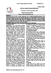
Information hiding has been widely used to protect the digital media contents [5]. It plays an important role in information security [6]. One of the branches of information hiding which focuses on secret communication is steganography. Steganography conceals the existence of the message which evades the attention of eavesdroppers. This makes steganography a good manner to communicate secret information through digital media[4]. Steganography has been applied in various digital media, such as audio, image, video and plain text. Among those various media, image is the most popular media to embed secret messages [7]. Image is an attractive media for steganography since the Human Visual System (HVS) is not sensitive to small changes within an image especially in the significantly changing region [8]. One of the earliest steganography methods in spatial domain is proposed by [9], called „ Least Significant Bit (LSB) Substitution‟. The data that hides in least significant bit may be known, hence this method is vulnerable to extraction by other parties[10]. Generally, spatial domain method are vulnerable against visual attack and pixel alteration [11]. On the other hand transform domain methods are more robust against image processing operations due to its hiding scheme in significant areas of cover images [7][12]. In transform domain method, DCT is widely used to transform an image into its frequency domain [13], II. DISCRETE WAVELET TRANSFORM In image processing, 2-Dimensional Discrete Wavelet Transform (2D-DWT) decompose an image into four 2dimensional sub-bands: LL, HL, LH, and HH. The LL represents the average value of low frequency signals of the image, while HL, LH and HH bands represent the horizontal, vertical and diagonal features of the image respectively. Basically, two dimensional wavelet transform is done by applying one dimensional wavelet filter in horizontal order followed by vertical order. Figure 1 depicts the processing levels of discrete wavelet transform.
143802-1919-IJVIPNS-IJENS © April 2014 IJENS
IJENS
International Journal of Video&Image Processing and Network Security IJVIPNS-IJENS Vol:14 No:02
pi, j p i 1, j
2
p i , j 1 p i 1, j 1
Level 0
represents a 2x2 block of image where pi,j is a pixel at row i and column j on each block of an image. Then, IHWT will be performed on each block of image to get wavelet coefficients in subbands cA or LL, cH or HL, cV or LH and cD or HH, as follows:
p i , j p i , j 1 p i 1, j p i 1, j 1 2 2 cA 2
Level 1
p i , j p i , j 1 p i 1, j p i 1, j 1 cH 2 p i , j p i , j 1 p i 1, j p i 1, j 1 cV 2 2
Level 2
cD pi , j pi , j 1 pi 1, j pi 1, j 1 Fig. 1. The levels of Discrete Wavelet Transformation of the Baboon image
III. INTEGER WAVELET TRANSFORM A DWT results in floating point coefficients [14]. Even though the inputs are integers as a representation of pixels value of an image, the wavelet coefficients no longer consists of integer [15]. Therefore, the transform coefficients alteration during an embedding process will produce reconstructed image which is no longer guaranteed to have integer values. Meanwhile any truncations of the floating point values into integer values may result in a loss of hidden information. On the other hand, an Integer Wavelet Transform (IWT), also called second-generation wavelets, is more flexible and able to define wavelet basis on an irregular grid or an interval [7]. The coefficients in IWT are represented as finite precision numbers which maps integers to integers [15]. It avoids the problem of floating point precision of the DWT [16]. IV. INTEGER HAAR WAVELET TRANSFORM Due to the advantage of wavelet transform, especially integer wavelet transform, researchers prefer to use the Integer Haar Wavelet Transform (IHWT) through a lifting scheme that has been used by [17] to works on frequency domain of an image. This IHWT is developed from Discrete Haar Wavelet Transform via a lifting scheme. It transforms integer pixel values of an image into the integer wavelet coefficients and vice versa. In order to transform an image into wavelet subbands, an image is divided into 2x2 non-overlapping blocks. Let
To reconstruct the wavelet coefficient, Inverse Integer Haar Wavelet Transform (IIHWT) is performed on each individual coefficient of each subband. This will result in block of 2x2 pixel size. Let
p' i , j 1 p' i , j p' i 1, j p' i 1, j 1 represents block of reconstructed image where cD 1 1 cH 2 cV 1 p' i , j cA 2 2
cD 1 p' i , j 1 c' i , j cH 2
p' i 1, j
cD 1 cH cD 1 2 cV 1 cA cV 2 2
cD 1 p' i , j 1 c' i , j cH 2 V. COEFFICIENT DIFFERENCE The difference value between two neighboring wavelet coefficients on each subband is used as a mean to hide the
143802-1919-IJVIPNS-IJENS © April 2014 IJENS
IJENS
International Journal of Video&Image Processing and Network Security IJVIPNS-IJENS Vol:14 No:02 message. Naturally, this technique is known as „Coefficient Difference‟ which is adapted from PVD method by [18]. Coefficient Difference method locates and embeds secret messages in these different values in finite precision number that suitable within the Integer Wavelet Transform. A. Embedding Process In this research study, a random key is used to scramble the embedding location at the both embedding and extraction process. As shown in Figure 2, the symmetric key is also used to encrypt the messages before embedding them into the cover images and decrypt the extracted messages from the stego image. Prior to the process of embedding and extraction, threshold values need to be determined first. The threshold values are used to prevent pixel values fall off the range of [0, 255] as well as to determine the number(s) of embedded bit(s) in each adjacent coefficients.
2.
3. 4.
5.
3
where r is the group range, lk is the lower bound of group k and c is the bit capacity of each adjacent coefficients. Perform Integer Haar Wavelet Transform (IHWT) on the cover image to decompose it into four wavelet coefficient: LL, HL, LH, and HH. Convert the secret message into a sequence of 8-bit binary values as a bit stream of message. Get the random secret key that will be used to: a. Generate random unsigned integer 8-bit (uint8) numbers to encrypt the message using XOR encryption method. b. Generate pseudorandom permutation to scramble the embedding location. Calculate the difference value (di) between two adjacent coefficients of block i: di = gi – gi+1
Embedding Algorithm Cover Image
Threshold
Key
1-Level IHWT
Message Binary Conversion
Wavelet Coefficient
Coefficient Difference
6.
where di is the difference value between gi and gi+1 as they are two adjacent coefficients of block i. Embed the bit(s) of message according to the wavelet coefficients: a. Assign the absolute difference value according to the group k, such that:
Bitstream
l k d i l k 1
Embeds Message
b. Inverse IHWT
Embedded Coefficient
c.
Stego Image
d. Fig. 2. The Embedding Process
The embedding process bang employed in this research study is as follows; 1. Define the threshold value (T) to use for: a. Preventing pixel value fall off of range of [0 255] after embedding: b. if p( x, y) T T , p( x, y) if p( x, y) 255 T 255 T ,
c.
where p(x, y) is the pixel value at row x and column y of cover image, is the integer weighting value, and T is the threshold value. The number of 255 is the maximum value of 8-bit image. Determining the group range (r), the lower bound (lk) of each group, and the bit capacity (c) : r
= 2T
lk c
28 T 1
kr k 0
= log2r
Take number of bit(s) from the bit stream of message according to c. Get the decimal value of taken bit(s) as embedded bit(s). Sum the lower bound and decimal values of taken bit(s) to get the new difference value (di’). di’ = bi + lk
e.
where di’ is the new difference value after embedding, bi is the decimal value of embedded bit(s). Readjust the two adjacent coefficient, to applied di’ and get the new (embedded) coefficient value:
Let f be the embedding function for the given two neighboring coefficients (gi , gi+1) m m ( gi , gi 1 ), m even 2 2 f ( gi , gi 1 ) ( gi m , gi 1 m ), m odd 2 2
where gi and gi+1 are two adjacent coefficients, while mi is equal to |di| – |d’i|, • is round-down operator, and • is round-up operator. The subscript i maybe dropped upon knowing the context of block i within an input image, such that:
143802-1919-IJVIPNS-IJENS © April 2014 IJENS
IJENS
International Journal of Video&Image Processing and Network Security IJVIPNS-IJENS Vol:14 No:02 mi = |di| – |d’i| di = gi − gi+1 di’ = g’i – g’i+1
7.
7.
where g’i and g’i+1 are two adjacent new coefficient values coming out of the embedding process. After all messages have been embedded or maximum capacity has been reached, apply Inverse IHWT on the subbands to get the stego image.
B. Extraction Process Message is extracted from stego images using the predefined threshold value and key. The same key is used to get the scrambled embedding location as well as to decrypt the extracted message from the stego images. Figure 3 depicts the extraction process of the secret messages from a cover image.
Cover Image
Extraction Algorithm
1-Level IHWT
Threshold
Wavelet Coefficient
Coefficient Difference
Extract Message
Integer Conversion
Message
Fig. 3. The Extraction Process
The step-by-step process of the extraction process is as follows; 1.
2. 3. 4.
5.
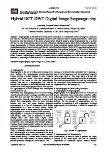
Convert the embedded value into binary string to get the part of bit stream of message. 8. Get the next embedding location using predefined key. 9. Repeat step 4 – 8 until the entire bit stream of message is fully extracted. 10. Convert the entire bit stream into integer value of 8-bits to get the message. 11. Decrypt the message using predefined key to get the original message. VI. EXPERIMENTAL RESULTS Six standard color images with a size of 512x512 pixels have been chosen as cover images to check on the effectiveness of the proposed technique as shown in Figure 4. Mean while a small UTeM color logo with size of 128x128 pixels is used as the secret message as shown in Figure 9. A. Image Quality Measurements In order to measure the image quality, the Structural Similarity (SSIM) from [19] and the standard Peak Signal to Noise Ratio (PSNR) are used. In addition, the standard Root Mean Squared Error (RMSE) is used to calculate the error rate on the extracted message.
Key
Bitstream
4
Perform Inverse Integer Haar Wavelet Transform (IIHWT) on the stego image to decompose it into four wavelet coefficients subbands: LL, HL, LH, and HH. Use the predefined threshold value to determine the lower bound and the range of groups of coefficient difference. Get the embedding location using the secret key on each subband. Get the absolute difference value between two adjacent coefficients of embedded coefficients. di’ = g’i – g’i+1 Assign the absolute difference value according to the group k, such that:
B. Determination of Threshold Threshold value determines the number of bit(s) to be embedded in each adjacent coefficient. Initially, threshold value of 1 to 4 is used as initial values. Then, 100,000 random integer numbers between range of [0, 255] are generated using specified key and then embedded in detail coefficient subbands (HL, LH, and HH). The comparison between maximum capacity and imperceptibility is used to define the proper threshold values. SSIM measurement is used to measure the quality of the stego image against hidden messages since it is able to extract the structural information and give a good approximation to measure the image quality [19].
(a)
(b)
(c)
(d)
(e)
(f)
l k d ' i l k 1 6.
Subtract the absolute difference value with the lower bound, to get the decimal value of embedded bit(s).
bi d ' i l k
Fig. 4. The cover images: (a) Baboon, (b) F16, (c) House, (d) Lena, (e) Peppers, (f) Sailboat
143802-1919-IJVIPNS-IJENS © April 2014 IJENS
IJENS
International Journal of Video&Image Processing and Network Security IJVIPNS-IJENS Vol:14 No:02
5
SSIM 1.00
Baboon
0.99
F16
0.98
House
0.97
Lena Fig. 6. Key
0.96 0.95 0.375
Peppers Sailboat 0.750
1.125
1.500
Capacity (bpp) Fig. 5. Capacity versus Imperceptibility
Figure 5 shows that the measure on imperceptibility given by SSIM decreases significantly when the size embedded messages exceed 1.125 bpp (i.e. for a threshold value of 3). Moreover, at the threshold value of 4 which gives capacity of 1.5 bpp, the quality of stego images coming out of cover images in Figure 4 starts to seriously degrade. The threshold value of 1 has small capacity of 0.375 bpp. On the other hand, the threshold values of 2 and 3 have large capacity of 0.750 and 1.125 respectively while maintaining good imperceptibility. Hence, the threshold values of 2 and 3 are selected to be suitable threshold levels to embed the message since it can achieve both high capacity and imperceptibility. C. The Stego Images Medium and high frequency image signals carry high imperceptibility. The message is preferably embedded into medium and high coefficient of the transformed cover image that is HL, LH, and HH. HH is the highest imperceptibility subband, hence the order of the subbands for embedding the message is HH, LH, then HL. First, the message is embedded into HH subband, then if the message exceed the capacity of the subband, the rest of messages are embeds into LH, and HL consecutively.
Fig. 7. Encrypted Message
2.) Message Embedding The image messages are embedded into all of cover images with the both threshold values (T) of 2 and 3. Then, the images qualities are measured using PSNR and SSIM. Table I Qualities of Stego Images PSNR
SSIM
Stego Images
T =2
T=3
T=2
T=3
Baboon
51.3744
50.2626
0.9991
0.9990
F16
51.4001
50.2805
0.9969
0.9963
House
51.1714
49.8420
0.9976
0.9971
Lena
51.4401
50.3481
0.9973
0.9968
Peppers
47.8867
45.6746
0.9960
0.9944
Sailboat
51.0616
49.6814
0.9980
0.9976
1.) Message Encryption Prior to embedding into a cover image, the message is encrypted using basic exclusive-or XOR operation. An input secret key shall be used to generate pseudo-random unsigned integer 8-bit (uint8) numbers that will be used for the encryption as shown in Figure 6 and Figure 7.
143802-1919-IJVIPNS-IJENS © April 2014 IJENS
IJENS
International Journal of Video&Image Processing and Network Security IJVIPNS-IJENS Vol:14 No:02 Quality of Stego Images
T =2
PSNR
T=3 52 50 48
6
Let us take a sample Lena image is used as cover message. Then color image message, basic UTeM logo as depicted in Figure 9a, is embedded into the cover image for threshold values of 2 and 3. JPEG2000 compression with compression ratios of 50%, 25%, and 10% are performed on the stego image and then the message is extracted from the cover image. The qualities of the messages are measured using SSIM and Root Mean Squared Error (RMSE) which is the square root value of MSE.
46 44 42 Baboon
SSIM
F16
House
Lena
Peppers Sailboat
Quality of Stego Images
T=2
(a)
(b)
(c)
(d)
T=3 1.000 0.999 0.998 0.997 0.996 0.995 0.994
Fig. 9. Extracted Color Message from Compressed Lena Image (T=3) coming out from JPEG2000 with compression ratios: (a) original message, (b) 50%, (c) 25%, (d) 10%.
0.993 0.992 Baboon
F16
House
Lena
Peppers Sailboat Table II Qualities of Extracted Message under JPEG2000 Compression
Fig. 8. Qualities of Stego Images
Table I and Figure 8 show that the stego image with threshold value of 2 has better image qualities than the threshold value of 3. D. The Stego Image under JPEG2000 Compression This section will test the strength of the proposed technique under various compression ratios of JPEG2000. A slightly different embedding order is chosen in order to preserve the message under such strong compression. The color cover image is transformed from RGB (Red, Green, Blue) color channels into YCbCr (Luminance, Chrominance Blue, Chrominance Red) channels. Given a raw color image as a secret message, the R, G, and B color channels of color image message are embedded into Y, Cb, and Cr channels of color cover image respectively. The message is embedded into low frequency subband that is LL, and middle frequency subbands that is HL, and LH. Since, LL subband has highest robustness followed by HL and LH.
Extracted Color Image Message Compression Ratio
RMSE
SSIM
T=2
T=3
T=2
T=3
50%
93.83
71.90
0.2056
0.3619
25%
110.43
95.92
0.0714
0.2037
10%
115.04
109.55
0.0176
0.0693
This results show that the technique used in this paper is relatively robust against the strong JPEG2000 Compression. This technique is also applicable to an image watermarking.
143802-1919-IJVIPNS-IJENS © April 2014 IJENS
IJENS
International Journal of Video&Image Processing and Network Security IJVIPNS-IJENS Vol:14 No:02
7
comparison between the proposed method with the existing method from [7] in case of embedding text message.
Quality of Extracted Image Message under JPEG 2000 Compression RMSE 120
T=2
110
T=3
100
1.) Imperceptibility In this comparison test, 2000 text characters are embedded into each subband of grayscale images. As given earlier, an image quality is measured using PSNR, This time, the message size expressed in „byte‟ since the message characters come in bytes.
90 80
Table III Comparison of Imperceptibility
70
PSNR
60 0%
10%
20% 30% Compression Rate
40%
Subband
Bhattacharyya and Sanyal (2010)
Proposed (Threshold =3)
Proposed (Threshold =2)
LL
35.8111
46.1056
50.0265
HL
33.4035
51.2563
53.5647
LH
31.0470
51.2998
53.6375
HH
35.1174
55.1575
56.6629
50%
Fig. 10. Qualities of Extracted Message under JPEG2000 Compression on root mean square error(RMSE)
Quality of Extracted Image Message under JPEG 2000 Compression SSIM 0.4
Comparison on Imperceptibility PSNR 60
0.3 50
Bhattacharyya and Sanyal (2010)
40
0.2
30
Proposed (Threshold =3)
T=2
0.1
20 T=3 10
0 0%
10%
20% 30% Compression Rate
40%
50%
Proposed (Threshold =2)
0 LL
HL LH Subband
Fig. 11. Qualities of Extracted Message under JPEG2000 various Compression according to SSIM
HH
Fig. 12. Comparison of Imperceptibility
Table 2 and Figure 10 shows that the image qualities of extracted message decreases with the increasing compression ratio. A smaller size of compressed image in terms of percentage give a higher compression ratio. The error rate that measured with RMSE increases and the image quality decreases with the increasing compression ratio. The threshold value of 3 performs better than the threshold value of 2 in terms of preserving the message. At the same time, the quality of the image message degrades as the compression ratio goes up, as shown in Figure 11, in terms of SSIM. E. Comparison with Existing Method In 2010, [7] proposed a method to embed the text message on Integer Haar Wavelet Transform domain called „Pixel Mapping Method (PMM)‟. This section will discuss the
Table III and Figure 12 shows that the proposed method has outperformed the previous works by Bhattacharyya and Sanyal in term of capacity versus imperceptibility. 2.) Maximum Capacity In order to check on capacity measurement, A grayscale Lena image with size 128x128, 256x256, and 512x512 has been used as cover image. The message is embedded into all four subbands of the cover image. Table 4 shows that the proposed method with Threshold value of 3 has outperformed the existing method by [7] in term of Maximum Capacity available to embed a secret message.
143802-1919-IJVIPNS-IJENS © April 2014 IJENS
IJENS
International Journal of Video&Image Processing and Network Security IJVIPNS-IJENS Vol:14 No:02
Image Size
Table IV Comparison on Maximum Capacity Proposed Proposed Bhattacharyya Method Method and Sanyal (Threshold (Threshold (2010) T=2) T=3)
128x128
2240
2048
3072
256x256
9536
8192
12288
512x512
40048
32768
49152
Capacity (Byte) 60000 50000 40000
Comparison on Maximum Capacity Bhattacharyya and Sanyal (2010) Proposed (Threshold =3) Proposed (Threshold =2)
30000 20000 10000 0 0
128
256 384 Image Size ( n n )
512
Fig. 13. Comparison of Maximum Capacity
Figure 13 shows that the proposed method with Threshold value of 3 has outperformed the existing method by [7] in term of the maximum capacity of the secret message for which the cover image can carry. VII. CONCLUSION Digital image steganography becomes an important manner to hide the existence of secret message. This paper proposes a method to hide the data on the Integer Haar Wavelet Transform domain by calculating the difference between two neighboring wavelet coefficients. In this coefficient difference computed in finite precision number is found to be suitably compatible with the Integer Wavelet Transform. Two threshold values are used to embed the message into cover images. The experimental results show that the threshold value of 2 gives better image qualities, while the threshold value of 3 provides larger capacity and more robustness against JPEG2000 Compression. In comparison to another method which employs IHWT with Pixel Mapping Method (PMM), the proposed method which utilizes IHWT with Coefficient Difference has achieved better result. The proposed method with threshold values of 2 has outperformed the Bhattacharyya and Sanyal‟s method in terms of stego image quality. At the same time, the proposed method with threshold value of 3 has achieved higher maximum message capacity than Bhattacharyya and Sanyal‟s method.
8
ACKNOWLEDGMENTS The authors would like to express a very special thank to Ministry of Higher Education (MOHE), Malaysia for providing financial support on this research project by Fundamental Research Grant Scheme (FRGS/2012/FTMK/SG05/03/1/F00141). REFERENCES [1] S. N. Mali, P. M. Patil, and R. M. Jalnekar, “Robust and Secured ImageAdaptive Data Hiding,” Digit. Signal Process., vol. 22, no. 2, pp. 314– 323, Mar. 2012. [2] P. Tsai, Y.-C. Hu, and H.-L. Yeh, “Reversible Image Hiding Scheme Using Predictive Coding and Histogram Shifting,” Signal Processing, vol. 89, no. 6, pp. 1129–1143, Jun. 2009. [3] X. Liao, Q. Wen, and J. Zhang, “A Steganographic Method for Digital Images with Four-Pixel Differencing and Modified LSB Substitution,” J. Vis. Commun. Image Represent., vol. 22, no. 1, pp. 1–8, 2011. [4] C.-H. Yang, C.-Y. Weng, H.-K. Tso, and S.-J. Wang, “A Data Hiding Scheme Using the Varieties of Pixel-Value Differencing in Multimedia Images,” J. Syst. Softw., vol. 84, no. 4, pp. 669–678, Apr. 2011. [5] C.-F. Lee, H.-L. Chen, and H.-K. Tso, “Embedding Capacity Raising in Reversible Data Hiding Based on Prediction of Difference Expansion,” J. Syst. Softw., vol. 83, no. 10, pp. 1864–1872, Oct. 2010. [6] H. Luo, F.-X. Yu, H. Chen, Z.-L. Huang, H. Li, and P.-H. Wang, “Reversible Data Hiding Based on Block Median Preservation,” Inf. Sci. (Ny)., vol. 181, no. 2, pp. 308–328, Jan. 2011. [7] S. Bhattacharyya and G. Sanyal, “Data Hiding in Images in Discrete Wavelet Domain Using PMM,” World Acad. Sci. Eng. Technol., vol. 44, pp. 597–605, 2010. [8] N. A. Abu, F. Ernawan, N. Suryana, and S. Sahib, “Image Watermarking Using Psychovisual Threshold Over the Edge,” in Proceedings of the 2013 International Conference on Information and Communication Technology (ICT-EurAsia 2013), 2013, pp. 519–527. [9] C. Kurak and J. McHugh, “A Cautionary Note on Image Downgrading,” in Computer Security Applications Conference, 1992. [10] A. A. Shejul and U. L. Kulkarni, “A DWT Based Approach for Steganography Using Biometrics,” in International Conference on Data Storage and Data Engineering, 2010, pp. 39–43. [11] L. Fan, T. Gao, Q. Yang, and Y. Cao, “An Extended Matrix Encoding Algorithm for Steganography of High Embedding Efficiency,” Comput. Electr. Eng., vol. 37, no. 6, pp. 973–981, Nov. 2011. [12] S. Bhattacharyya, “A Survey of Steganography and Steganalysis Technique in Image, Text, Audio and Video as Cover Carrier,” J. Glob. Res. Comput. Sci., vol. 2, no. 4, pp. 1 – 16, 2011. [13] N. A. Abu, F. Ernawan, and S. Sahib, “Psychovisual Model on Discrete Orthonormal Transform,” in International Conference on Mathematical Sciences and Statistics 2013 (IICMSS2013), 2013, vol. 309, pp. 309–314. [14] R. O. El Safy, H. H. Zayed, and A. El Dessouki, “An Adaptive Steganographic Technique Based on Integer Wavelet Transform,” in International Conference on Networking and Media Convergence (ICNM), 2009, pp. 111–117. [15] S. Hemalatha, A. Renuka, U. Dinesh Acharya, and P. R. Kamath, “A Secure Image Steganography Technique Using Integer Wavelet Transform,” in World Congress on Information and Communication Technologies, 2012, pp. 755–758. [16] N. Raftari and A. M. E. Moghadam, “Digital Image Steganography Based on Integer Wavelet Transform and Assignment Algorithm,” in 2012 Sixth Asia Modelling Symposium, 2012, pp. 87–92. [17] J. Xu, A. H. Sung, P. Shi, and Q. Liu, “JPEG Compression Immune Steganography Using Wavelet Transform,” in International Conference on Information Technology: Coding and Computing (ITCC), Volume: 2, 2004, pp. 704–708. [18] D. Wu and W. Tsai, “A Steganographic Method for Images by PixelValue Differencing,” Pattern Recognit. Lett., vol. 24, no. 9–10, pp. 1613–1626, 2003. [19] Z. Wang, A. C. Bovik, H. R. Sheikh, and E. P. Simoncelli, “Image Quality Assessment: From Error Visibility to Structural Similarity,” IEEE Trans. Image Process., vol. 13, no. 4, pp. 600–612, Apr. 2004.
143802-1919-IJVIPNS-IJENS © April 2014 IJENS
IJENS