(WPAN) [1] and IEEE 802.11ad wireless local area network. (WLAN) [2]. Millimeter-wave communication system promises achiev- able throughput in the order of ...
2658
IEEE TRANSACTIONS ON WIRELESS COMMUNICATIONS, VOL. 11, NO. 7, JULY 2012
Scalable Heuristic STDMA Scheduling Scheme for Practical Multi-Gbps Millimeter-Wave WPAN and WLAN Systems Chin-Sean Sum and Hiroshi Harada
Abstract—This paper proposes a hybrid SDMA/TDMA scalable heuristic scheduling scheme for throughput enhancement in practical multi-Gbps millimeter-wave systems with directional antenna. A theoretical cross layer design framework is proposed taking into consideration the MAC layer, PHY layer and millimeter-wave propagation channels based on actual measurements. The proposed generalized framework can be well suited into two of the most prominent industrial wireless communication standards, namely IEEE 802.15.3c WPAN and IEEE 802.11ad WLAN. Employing the developed theoretical framework, evaluation for throughput and error performance is conducted with validation of computer simulations. Firstly, it is found that the proposed STDMA scheme is capable of improving system throughput in the order of typically 4 to 8dB. Secondly, the proposed scheduling scheme offers superior design flexibility through its scalability features, with the optimum heuristic order observed at the 13-th order, a reasonably low value considering the performance enhancement that can be obtained. Lastly, the typical allowable interference in a network due to coexisting communication links sharing the same time slot is recommended to be controlled below -20dB. Numerical results other then the typical findings are detailed in the paper. Index Terms—Hybrid SDMA/TDMA, scheduling, millimeter-wave, directional WLAN.
scalable heuristic antenna, WPAN,
I. I NTRODUCTION ILLIMETER-WAVE (mmWave) band technology for ultra-high-speed wireless communications is envisioned to drive consumer-oriented electronics into a new era of wireless uncompressed video streaming, super broadband internet access and flash sync-n-go applications. Towards realizing this vision, the wireless community has witnessed intensed efforts from areas of academia, industry and regulation. Particularly, the industrial community has responded to the fast growing popularity by mobilizing huge efforts in international standardization activities. Among other initiatives, are the prominent IEEE 802.15.3c wireless personal area network (WPAN) [1] and IEEE 802.11ad wireless local area network (WLAN) [2]. Millimeter-wave communication system promises achievable throughput in the order of multi-Gbps in order to support the targeted use cases. To uphold this claim, system designers
M
Manuscript received September 27, 2011; revised February 2, 2012; accepted April 12, 2012. The associate editor coordinating the review of this paper and approving it for publication was G. Abreu. The authors are with the National Institute of Information and Communications Technology (NICT), Japan (e-mail: {sum, harada}@nict.go.jp). Digital Object Identifier 10.1109/TWC.2012.051412.111774
have come up with various solutions manipulating radio resources such as time, frequency and space. One typical solution utilizing physical space is the space division multiple access (SDMA) [3]. SDMA is an approach to boost system throughput by increasing transceiving gain through beamforming or switched directional communications. In mmWave systems, SDMA is essential to overcome the large free space path loss (FSPL). Besides SDMA, time division multiple access (TDMA) [4] is another solution to facilitate multi-user and low latency data communications. In mmWave systems, TDMA is commonly used to enable time-sensitive communications requiring big chunks of data to be sent within a very short period of time. In several of the currently most influential industrial specifications [1], [2], [5], [6], SDMA and TDMA have been selected to construct the basic design architecture. This paper intends to further harvest the advantages offered by SDMA and TDMA in a combinatorial manner rather than as separate schemes. For this purpose, a hybrid STDMA scheme with flexible scheduling capability taking into account practical and realistic design considerations is proposed. The STDMA scheme utilizes the mmWave band capability of accommodating large data burst in time and the relatively small interference zone due to large FSPL among users in space, to achieve combined time-spatial diversity, hence throughput enhancement. In this paper, a scalable heuristic STDMA scheduling engine is proposed to flexibly and effectively schedule different users determined to have negligible interference to each other to share the same TDMA time slot. The preliminary idea of utilizing both time and space dimensions in the mmWave systems was proposed by the authors back in [7]. The contribution of this paper is essentially four-fold: (a) designed, modeled and evaluated a STDMA heuristic scheduling scheme with demonstrated results showing significant throughput improvement, (b) provided a cross-layer MAC and PHY layer design over realistic mmWave propagation channel based on actual measured data, (c) provided a practical industrial design with reference to use case scenarios, region-specific regulatory requirements and standardization specifications, and (d) provided analysis on performance improvement and complexity requirement to facilitate cost-performance tradeoff assessment. To the best knowledge of the authors based on extensive literature review, there is no existing literature that carries such broad coverage and at the same time in-depth analysis on the topic. Fractions of this paper were reported in
c 2012 IEEE 1536-1276/12$31.00 �
SUM and HARADA: SCALABLE HEURISTIC STDMA SCHEDULING SCHEME FOR PRACTICAL MULTI-GBPS MILLIMETER-WAVE WPAN . . .
2659
B. Time, Frequency and Spatial Diversity
Fig. 1. Illustration of typical use case scenarios for mmWave communication systems.
our previous publications [8]–[10]. The main novel contribution in this paper as compared to [8]–[10] is the incorporation and generalization of the proposed mechanism to suit both WPAN and WLAN system architecture. The effort for WPAN system in [8]–[10] is repeated for WLAN systems from the aspects of specific use case scenarios, network architecture, MAC/PHY layer designs and performance evaluation.
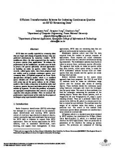
II. P OTENTIAL OF STDMA IN M ILLIMETER - WAVE WPAN/WLAN A. Use case Figure 1 illustrates the typical use case scenarios for an mmWave system in a residential environment. In the figure, two primary usage models are shown, uncompressed video streaming and super broadband internet connection. For uncompressed video streaming, it is very common for modern households to have flat screen TVs installed in the living room, and receive streams of uncompressed high definition (HDTV) files from an mmWave set top box. Super broadband internet connection is another major use case targeted by mmWave systems. Ultra-high-speed web-browsing and data exchange are among the potential applications supported by super broadband internet connection. Similarly, it is not uncommon to have multiple connectivities deployed in modern households supporting different users in the living room, bedrooms or even at the patio or balcony simultaneously. Connectivity within the house is established in mmWave air interface while the gateway to the outside world can be either copper wire or optical fiber connections. Referring to Figure 1, it is also clear that the connectivity between devices in the scenarios are primarily static and within line of sight (LOS). These characteristics will be the main assumptions used in this paper for system modeling and performance analysis. Additionally, the identified usage models suggest that the architecture is commonly a centralized network, with a coordinator device controlling the reference timing and radio resources for the client devices within the network.
The mmWave communication system possesses essential characteristics for system designers to take advantage on time, frequency and spatial diversity. In the time domain, the mmWave signal has a very short symbol duration in the order of nanoseconds, thus enabling transmissions of big chunks of data within a short period. In this case, a relatively shorter time slot is sufficient for a large burst of data. In other words, a larger number of time-multiplexing users can be supported within a fixed duration as compared to sub-10GHz systems. In the frequency domain, the spectral bands in the 60GHz region is largely unused, unlike the congested sub-10GHz bands. There is a worldwide 9GHz bandwidth for unlicensed use of mmWave systems. Further details of the available spectrum resource are given in Section III-A. In the spatial domain, mmWave signal has very high reusability due to the huge FSPL in signal propagation. The FSPL for 60GHz signal is 68dB for 1 meter, 74dB for 2 meters and 78dB for 3 meters. This characteristic indicates that more communication devices can be allowed to coexist in close proximity since the mutual interference decreases drastically in relation to operating range. Spatial diversity can be further enhanced if directional antennas are used. By combining all the three timefrequency-spatial domains, the potential of mmWave STDMA system in boosting achievable throughput and supporting more simultaneous users is very promising. III. D ESIGN A RCHITECTURE FOR M ILLIMETER -WAVE WPAN AND WLAN S YSTEMS This section provides an overview on the general design architecture for mmWave systems. While the generic architecture is constructed to model the behavior of a general mmWave system, in this paper, to further pronounce its practicality, the developed architecture is cross-mapped with two of the most prominent industrial designs for mmWave systems. The industrial systems are listed according to the date of completion, as the following: • IEEE 802.15.3c [1] Millimeter-wave-based WPAN PHY and MAC Specifications • IEEE 802.11ad [2] Millimeter-wave-based WLAN PHY and MAC Specifications In the following sections, the generic architecture will be constantly deduced into specific terminologies and framework defined in these documents. The core architecture of the mmWave systems are presented from the perspectives of channelization, network architecture, medium access control (MAC) layer design and physical (PHY) layer design. A. Regulatory Information As illustrated in Figure 2, there is a total of 9GHz frequency bandwidth allocated worldwide, with minor differences dependent on regulatory domains. The 9GHz band is divided into four channels, each occupying 2.16GHz. The lower and upper guard bands are set to 240MHz and 120MHz to reduce outof-band emissions. Major industrial standards including IEEE 802.15.3c [1], 802.11ad [2], ECMA [5] and WirelessHD [6] employ the same channelization.
2660
IEEE TRANSACTIONS ON WIRELESS COMMUNICATIONS, VOL. 11, NO. 7, JULY 2012
2160MHz
time
240MHz
57
120MHz
58
59
60
61
62
63
64
65
66 Frequency (GHz)
(a)
BEACON
CONTROL
(b)
BP
CAP
(c)
BTI
DATA
CTAP CTA
USA/Canada/Korea
CTA
Japan Europe Australia
Fig. 2.
Allocations of 60GHz inlicensed band in different countries.
A-BFT
AT
DTT CBAP
SP
SP
CBAP
Fig. 4. Network time segmentations: (a) generic timing segmentation; (b) 802.15.3c superframe structure; (c) 802.11ad beacon interval structure.
Link N R Link 3 Link 1
Coordinator Link 2 Network
Fig. 3.
Illustration of a typical mmWave network.
B. Network Architecture An mmWave network providing radio coverage with radius R comprises of M mmWave devices (DEVs), one of which is the network coordinator (NC). The NC is responsible of managing radio resources and timing reference for the network. The remaining M -1 DEVs may establish up to a total possible number of N ≤ M (M − 1) DEV-to-DEV communication links, hereon referred to as links. Each link is constructed by a transmitting DEV and a receiving DEV. Additionally, NC may also be a DEV in a link. In the 802.15.3c system, a network is known as a piconet, consisting an NC called piconet coordinator (PNC) and surrounding DEVs. On the other hand, in the 802.11ad system, the network is commonly known as personal basic service set (PBSS) with PBSS control point (PCP) as the BSS coordinator and network nodes known as stations (STAs). The illustration of the generic network architecture can be given in Figure 3. The scenario in Figure 3 is achievable by employing peer-topeer communication procedure specified in the 802.15.3 base standard [11] and direct link setup (DLS) procedure specified in the 802.11 base standard [12]. C. Basic MAC Architecture In order to provide timing reference in the network, segmentations are conducted on the total interval between two consecutive beacons. As shown in Figure 4(a), the generic timing segmentation divides the total duration into three parts, BEACON, CONTROL and DATA. The BEACON part constructs the duration for beacon transmission by the NC. The number of beacons may be single or multiple. The CONTROL part performs the basic DEV command-and-control (CnC) operations such as discovery, radio resource management, and etc. The channel access rules for this part is based on the carrier sense multiple access / collision avoidance
(CSMA/CA) mechanism. The DATA part consists of primarily data streaming among DEVs, although command and control operations are not prohibited. In this part, the channel access is based on the time division multiple access (TDMA) mechanism. Illustration for the network timing in the 802.15.3c system is shown in Figure 4(b). Here, BEACON is known as beacon period (BP). In the BP, an omni-directional beacon or multiple quasi-omni-directional beacons may be transmitted to facilitate discovery by surrounding DEVs. Quasi-omni-directional beacons may also be used as the early stage of beam-training for directional communications in later stages. CONTROL is known as contention access period (CAP) where CnC operations are performed based on CSMA/CA rules. MAC functionalities supported in 802.15.3c are such as DEV association, channel time management, peer discovery, synchronization, power management, frame aggregation, beamforming, directional communication and channel probing. DATA is known as the channel time access period (CTAP), performed by employing TDMA scheme. The control and management operations facilitating data streaming are performed in CAP i.e. the links are paired with respective communication time scheduled. In CTAP, the scheduled data streaming for the links will then take place accordingly. The interval between two consecutive beacons is called a superframe. Illustration for the network timing in the 802.11ad system is shown in Figure 4(c). BEACON is referred as beacon transmission interval (BTI) where directional beacon frames are transmitted in the directional band (DBand). CONTROL can be divided into association beamforming training (A-BFT) and announcement time (AT) periods. A-BFT is a period when beamforming training is conducted in DBand and AT is a request-response base management access period between the PCP and STAs. Basic MAC functionalities in 802.11ad are distribute coordination function (DCF), point coordination function (PCF), hybrid coordination function (HCF), beamforming, service period management, link adaptation and others. DATA is known as data transfer time (DTT), principally facilitating data streaming. There can be two types of channel access method in DTT, CSMA/CA in the contention based access period (CBAP) and TDMA in the service period (SP). The time slots for CBAP and SP are scheduled and announced to the participating STAs prior to the start of DTT. The interval between two consecutive beacons is simply known as a beacon interval (BI).
SUM and HARADA: SCALABLE HEURISTIC STDMA SCHEDULING SCHEME FOR PRACTICAL MULTI-GBPS MILLIMETER-WAVE WPAN . . .
A. CCI Monitoring Engine 1) Probing-Signal Period: The CCI-monitoring engine is activated by starting a CCI-probing session at the beginning of the contention free data streaming period, i.e. the first time slot of CTAP in 802.15.3c or that of DTT SP in 802.11ad. CCIprobing can be defined as a process to assess information of CCI in the links through transmitting and receiving probing frames. The time slot allocated for CCI-probing session, is known as the probing-signal period (PSP) and shall be contention free. In PSP, the NC gathers information of potential CCI generated by each transmitter (TX) towards respective receiver (RX) in the links. Note that there are a total of N number of links. Therefore, at the beginning of PSP, the device management entity (DME) of TX(n) i.e. the n-th TX posts a request to its MAC layer management entity (MLME), ordering the transmission the PSP probing frame. Transmitter TX(n) sends a probing frame to each p of the total P number of directions to cover an omni-directional-equivalent area, including all possible locations of RX(n=1) to RX(n=N ) . In the special case where TX(n) has an omni-directional antenna, P =1. The procedural details of the signaling flow in the PSP are shown in the message sequence chart (MSC) in Fig.5. First, TX(n=1) sends the probing frames to all p = 1, 2, ..., P directions, received by all RX(n=1,2...,N ) simultaneously. This is then followed by transmissions of TX(n=2) to TX(n=N )
TX(n) MLME
NC DME
Associated
MLMEsendPSPprobe.req
RX (n) MLME
NC MLME Associated
RX (n) DME Associated
TX(n =1), RX (n =1,2,㵺 ,N) , TX(n =1) direction p=1 p =1,2,...
TX(n =1), RX(n =1,2,㵺,N) , TX(n =1) direction p=P
For TX, n =1,2,...
TX (n =N), RX (n =1,2,㵺 ,N) , TX(n =N) direction p=1 (n =N)
p =1,2,...
(n =1,2,
,N)
㵺 TX , RX , TX(n =N) direction p=P
Probing Frames MLMEreceivePSPfeedback. cfm MLMEconstructCCImonitoring -table.req
RX (n =1) For RX, n =1,2,... RX (n =N) ACK Frames
MLMEreceivePSPprobe.ind
MLME-sendPSPfeedback.req
㪮㪠㪩㪜㪣㪜㪪㪪㩷㪤㪜㪛㪠㪬㪤
According to III-C, it is clear that most of the time sensitive data streaming will be conducted using the TDMA scheme, utilizing the diversity of time for multiple users. Additionally, spatial diversity can also be achieved from the dimensions of lower link-to-link separation as well as higher antenna directivity. In the 802.15.3c, there are MAC functions supporting beamforming and directional communications, while in the 802.11ad, there are beamforming and directional DBand communications. Interestingly, owing to the high degree of spatial diversity, TDMA time slots for data streaming can be further reused. In other words, unlike conventional TDMA schemes, one TDMA time slot is not necessarily occupied by only one but several links that are determined to be not interfering each other. This phenomena is especially significant in the mmWave systems with two dimensions of spatial diversity. The basic procedure of the STDMA mechanism are divided into the following steps: (a) Probe and record co-channel interference (CCI) of multiple links in the network (b) Construct the network CCI table consisting all CCI values from all link transmitters to all link receivers (c) Activate the heuristic STDMA scheduling algorithm to determine groups of links most suitable to share the same TDMA time slot (d) Arrange the TDMA time slots for actual data streaming according to the scheduler output Steps (a) and (b) are detailed in Section IV-A while steps (c) and (d) in Section IV-B.
TX(n) DME
㪮㪠㪩㪜㪣㪜㪪㪪㩷㪤㪜㪛㪠㪬㪤
IV. STDMA- BASED M ILLIMETER - WAVE MAC L AYER D ESIGN
2661
Fig. 5. Message sequence chart for the the PSP Operation. TX(n) : Transmitter of the n-th link. RX(n) : Receiver of the n-th link. TX(n=1,2,...N) : Transmitters of the n = 1, 2, ...N -th links. RX(n=1,2,...N) : Receivers of the n = 1, 2, ...N -th links. DME: device management entity. MLME: MAC layer management entity. Key ’.req’: request. Key ’.ind’: indication. Key ’.cfm’: confirm. n: link counter. p: antenna direction counter.
sequentially. Upon receiving the probing frames from TX(n=1) to TX(n=N ) , the MLME of RX(n) posts an indicator to its DME reporting the status. The DME will then post a request to MLME to reply with an acknowledgment signal to the NC. This signal shall be sent using the acknowledgment (ACK) frame. The ACK frame contains the signal power received from TX(n=1) to TX(n=N ) . Out of the N number of signals, only one is the desired signal and the rest are CCI generated by other links. All RXs are assumed to have already acquired the location of the NC during the association procedure. Therefore, only one transmission direction is needed by each respective RX to send the ACK frames to the NC. The MLME of the NC, upon receiving this ACK frame, conveys the confirmation of feedback to the NC-DME. The NC-DME will then request the MLME to construct the corresponding CCImonitoring table. 2) CCI-Monitoring Table: The outcome of the MSC in Fig.5 is the construction of the CCI-monitoring table by the NC-MLME, given as a two-dimensional N × N matrix in (1), where λ denotes the CCI value. The n-th row displays the CCI generated by TX(n) to all RX(n=1,2,...,N ). The n-th column displays the CCI received by RX(n) from all TX(n=1,2,...,N ). It is worth to take note that the diagonal elements in (1) are all zeros. This is because for each diagonal element, the TX and RX are belonging to the same desired link (i.e. the same n value), thus giving the desired signal level and not CCI. This CCI-monitoring table will be used as the input of the heuristic scheduling engine to optimize the STDMA parameters. B. STDMA Scheduling Engine The CCI-monitoring table produced in Section IV-A2 is utilized by the STDMA scheduling engine to facilitate optimal time slot sharing among links taking advantage on spatial diversity of both mmWave propagation characteristics and directional antenna.
2662
IEEE TRANSACTIONS ON WIRELESS COMMUNICATIONS, VOL. 11, NO. 7, JULY 2012
⎛ ΥCCI
0
⎜ ⎜ λTX(2) RX(1) =⎜ ⎜ .. ⎝ . λTX(N ) RX(1)
λTX(1) RX(2) 0 .. . ···
Ψ Ω x,y
λTX(1) RX(N ) .. .
0
λTX(N −1) RX(N ) 0
λTX(N ) RX(N −1)
1) Scalable Heuristic Scheduling Algorithm: In this paper, a flexible heuristic scheduling algorithm with α-order scalability is designed. The fundamental task of the scheduler is to determine and schedule the links that are able to coexist in time within the same TDMA time slot. The major parameters involved in the scheduling algorithm are as follows: α Γ
··· .. .
heuristic order of the scheduling algorithm maximum tolerable accumulative CCI, beyond which disallows more links to share the same TDMA time slot number of allocated TDMA time slots in the network number of links that are able to share the same TDMA time slot matrices containing identifiers of the coexistable links
Besides the scheduler parameters, there are also operational parameters specified to facilitate the flow of the algorithm, and are transparent externally. The parameters are counters such as αcnt , Ψcnt , λtot , λsel , i and j. The basic idea of the proposed design is to allow communications links in close proximity to share the same time slot. In order to ensure that the performance of the coexisting links is not compromised to an intolerable point, the total effective CCI, determined by accumulatively adding the CCI generated by each link should be made lower than Γ. As long λtot does not exceed Γ, more CCI links can be added into λtot . In other words, more coexisting links can be schedule into the same TDMA slot. Once λtot exceeds Γ, no further additional links will be scheduled into that particular TDMA slot. Threshold Γ is controlled by the PHY layer to ensure that the accumulative CCI generated by the coexisting links does not degrade the system performance to an intolerable level exceeding the requirements of usage models and standard technical specifications. For details on how the parameters are utilized, refer Section VI-A. As shown in Figure 6, the activation of the scheduler starts by loading the CCI-monitoring table ΥCCI in (1) constructed based on the process in Section IV-A2. Next, the main scheduling parameters, α, Γ and Ψ are loaded into the scheduler. All operational parameters are initialized. By employing procedure P 1, the column with the lowest λ value is selected, followed by procedure P 2, where the lowest λ element can be determined. Procedures P 1 and P 2 effectively provide the lowest received λ value in a given link. Then, table lookup operation is performed by the scheduler to find other links with respective λ values to be added to the same TDMA time slot. With the looping procedure denoted as L1, λ values of other links are added accumulatively to share the same TDMA time slot, one after another as long as the following
⎞ ⎟ ⎟ ⎟ ⎟ ⎠
(1)
N ×N
condition is satisfied: λtot =
Ω �
λsel (n� ) ≤ Γ
(2)
n� =1
where λtot is the accumulative CCI contributed by the added links into the same time slot, λsel is the CCI value selected through process P 3 while n� < Ω. Here, it is worth to note that process P 3 selects the maximum CCI value from a set of all possible mutual interference to be added into λtot . Step P 3 is to ensure that all possible accumulative CCI values in coexisting links are considered during the decision stage of time slot sharing. Every loop L1 adds a new coexistable link (recorded as matrices x and y) into the same TDMA time slot, and updates λtot followed by comparison with Γ. To avoid infinite looping in L1, the link already added into the time slot is excluded from the following rounds of iteration. If λtot exceeds Γ then the loop is terminated and all the links recorded in matrices x and y (with λtot < Γ) will be reported to the NC-MLME for TDMA time slot sharing execution. At this point, a single α order in the heuristic algorithm has taken place. Next, the scheduler checks the value of α and determines whether another cycle is required. If the current α value is lower than the preset α value, the algorithm moves into looping procedure denoted as L2, where L1 is executed all over again from the beginning. Similarly, in order to avoid infinite looping, upon completion of each L2 iteration, the processed L1 procedure in is excluded from the following rounds of L2 iteration. Loop L2 will be terminated as soon as α reaches the preset value. Procedures L1 and L2 determine the total number of links that are able to be scheduled to occupy the same TDMA time slot through α order of iterations. Assuming that a total of Ψ number of time slot is allocated, after a group of links are scheduled for one particular time slot, looping procedure L3 will be activated to refresh all parameters and the same process can be repeated for other time slots, until all Ψ time slots are occupied. The order α of the scheduler represents the intensity of the table-lookup operation. At α = 1, the scheduler simply determines one of the many possible combinations of the timeslot-sharing links. On the other hand, the highest possible value of α is equivalent to the number of available links N as described in Section III-B. At α=N , the algorithm is operating in an exhaustive heuristic searching process, considering all possible combinations. Alternatively, the simplest approach is the random scheduling method. This can be achieved by simply replacing processes P 1, P 2 and P 3 as random selection processes. The single parameter α that controls the scheduler operation intensity can be set as an input parameter into the system to achieve different levels
SUM and HARADA: SCALABLE HEURISTIC STDMA SCHEDULING SCHEME FOR PRACTICAL MULTI-GBPS MILLIMETER-WAVE WPAN . . .
Activate a -order Heuristic Scheduler
Eq.(3) expresses that the system complexity is dependent on parameters Ψ, α and Ω. 3) Scheduling Algorithm Overhead: Prior to scheduling TDMA time slots for links to coexist in contention free periods, the first or first few time slots have to be allocated for assessing the required information, as described in PSP operation in Section IV-A1. For the 802.15.3c system, one or multiple CTAs are needed, and for the 802.11ad system, one or multiple SPs are needed. Since the preparation stage taking place in PSP does not deliver actual data, it should be viewed as overhead. The signaling exchange in the PSP can be referred to Fig.5. The total time consumed by the PSP is given as: (4) TP SP = N Tprobe (P + 1)
Access CCI-monitoring table ϒCCI Load input parameters α, Γ and Ψ Set Ψcnt = 1 Set a cnt =1 Set i =1, j =1
Ψcnt = Ψ cnt + 1
Set λtot =0, Ω =1 Set matrices x=[ ] and y=[ ]
a cnt = a Cnt +1 i = i+1
P1
Assign xi to denote the column with the lowest λ value in ϒCCI
P2
Assign yj to denote the lowest λ value in column xi
L3 L2
where Tprobe is the duration of one probing signal, P is the total number of TX transmit directions in the PSP. 4) System Throughput: Upon obtaining Ω from the scheduling engine, the STDMA operation will be executed, i.e. arranging the scheduled links according to matrices x and y produced in Section IV-B, to occupy the same TDMA time slots for data streaming. The achievable system throughput Tsys is given as:
L1
P3 Compare λTX(xi)RX(yj) to λ TX(yj)RX(xi) Record xi and yj into matrices x and y
j = j+1
Select the largest value, assign as λsel Exclude the element in ϒCCI currently assigned as yj from the following selection process in P2 No
λtot = λtot + λsel Ω = Ω +1 λtot > Γ ?
Tsys = Sr · γP HY · γMAC · (1 − Pf e ) · E[Ω] No
Yes Exclude last elements of matrices x and y Send matrices x and y to NC-MLME a > a cnt ? Yes
No
Exclude the entire row in ϒCCI currently assigned as xi from the following selection process in P1
Ψ > Ψcnt ?
γMAC =
End Scheduler
Flow chart of the α-order STDMA heuristic scheduling procedure.
of performance improvement at the expense of increased complexity, in accordance to respective system and application demands. This characteristic is known as scalability of the scheduling mechanism. In Section VI, the system performance scaled to different parameter setting combinations is evaluated. 2) Algorithm Computational Complexity: This section discusses the required computational complexity based on different order of scheduling algorithm described in Section IV-B. Since mmWave systems have low power consumption requirements in certain use case scenarios, the requirements for circuitry complexity is also an essential consideration. Correspondingly, the computational speed of the proposed scheduling algorithm should be quantified. By employing the big-O notation in computational complexity theory, the upper bound of the algorithm complexity can be expressed in the total number of computational iterations, i.e. loops, as: ∈ ΨαΩ C
(3)
(5)
where Sr is the Nyquist bandwidth, γP HY and γMAC are the PHY and MAC overhead coefficients respectively, Pf e is the average frame error rate (FER) given in (21) and E[·] represents the mean value. Parameter E[Ω] is the output parameter from on the STDMA scheduler, representing the average value of Ω. The more efficient the scheduler performs, the higher E[Ω] becomes, and the higher the achievable throughput, at the expense of higher complexity. In the conventional TDMA, Ω is constantly set to 1. This gives the effective achievable throughput improvement Timp = Tsys × E[Ω]−1 E[Ω] . The MAC overhead coefficient is expressed as:
Yes
Fig. 6.
2663
Tf r TCF P · Tf r + TMIF S + Tprehead TCF P + TP SP
(6)
where Tf r = 1/Lf r is the frame duration, TMIF S is the duration for minimum interframe spacing (MIFS) inserted as guard time in between frame transmissions [1], [2], Tprehead is the duration of the frame preamble and header, and TCF P is the contention free period, i.e. CTAP for 802.15.3c and SP for 802.11ad. The PHY overhead coefficient is expressed as: γP HY =
RF EC Lmod LSF
(7)
where RF EC is the coding rate for the forward error correction (FEC) scheme, Lmod is the level of modulation scheme and Lmod is the spreading factor. V. M ILLIMETER - WAVE PHY L AYER D ESIGN The 802.15.3c and 802.11ad systems are multi-PHY systems utilizing both single carrier (SC) and orthogonal frequency multiplexing division (OFDM) modulations to address different application demands and market segments. SC PHY is specified to realize application with low complexity and
2664
IEEE TRANSACTIONS ON WIRELESS COMMUNICATIONS, VOL. 11, NO. 7, JULY 2012
low power requirements, while OFDM PHY mainly targets on high speed applications in fading environments. SC has been chosen as the common mode signaling in 802.15.3c system bridging different PHY layer designs [1], and as the Control PHY in 802.11ad system to conduct command and control messaging [2]. For this reason, the SC signaling will be used to conduct the PSP and all message exchanges related to the STDMA scheduling. In this paper, the proposed SC PHY layer design for mmWave system is based on our previous works [8]–[10]. A. Signal Model The transmitted signal is a typical binary phase shift keying (BPSK) signal. There are a total of n = 1, 2, ..., N number of communication links, with the n-th signal in the form: un (t) =
+∞ �
En bi ψ(t − iTb ) · cos(2πfc t + θn ), i=−∞
C. Receiver Model Propagating through the mmWave channel, the received signal can be represented by: +∞ L �
� � (n) En bi βl,n
N/Ω
r(t) =
n=1
q=−∞
n = 1, 2, ..., N
(8)
B. 60GHz Propagation Channel Model The propagation channel models (CMs) for mmWave band that characterize the behavior of the signal in the channel have been extensively investigated [14], [15]. Among other topics addressed, residential environment is essentially significant due to the use case models of several prominent applications. The following presents a generic representation of the mmWave channel properties. The channel impulse response of can be described as: ∞ � ∞ �
pq ι(t − εp − ϕp,q )ι(θ − Ξp − ξp,q ) h(t, θ) = κι(t) + (9) where ι(t) represents the impulse, t represents time and θ represents angle, pq is the complex amplitude of each ray, εp is the delay time of the p-th cluster, ϕp,q is the delay time of the q-th ray in the p-th cluster, Ξp is the angle of arrival of the p-th cluster, ξp,q is the angle arrival of the q-th ray in the p-th cluster. The direct path component κ is generated by using the statistical two-path model [16]. At the receiver, the propagation channel is modeled as a time-invariant, slow, independently-faded L path frequency selective fading Nakagami fading multipath signal as seen in the receiver. The channel decaying profile can be expressed as: � 1 − exp (−χ/L) �l = [exp (−χ(l − 1)/L)] 1 − exp (−χ) l = 1, 2, ..., L (10)
(11)
l=1
ψ(t − qTb − (l − 1)Tb − ςn ) cos(2πfc t + ϑl,n ) + η(t) where ςn is the delay of the n-th CCI signal with respect to the desired link (ς0 =0), ϑl,n is the phase of the l-th path of the n-th link’s received signal, η(t) is the additive white Gaussian noise (AWGN) with two-sided power spectral density of N0 /2, βl,n is the fading amplitude of the l-th path of the n-th CCI signal having a Nakagami distributed probability density funcm
where ψ(t) is the baseband signal with unit energy, Tb is the bit duration, En is the bit energy of the n-th user, bi is the i-th bit which is a random variable (RV) uniform on {+1,-1}, fc is the carrier frequency and θn is the instantaneous phase at the time of transmission uniform over {0,2π}. Referring to Section III-B, link n=0 is the desired link and n ∈ (1,2,...,N ) are all simultaneous links, of which a total of N/Ω links sharing the same TDMA time slot may generate CCI to the desired link. These CCI values are the input parameters to the STDMA engine as described in Section IV-A.
p=0 q=0
where χ is the channel decaying factor and L is the total multipath in the channel.
tion given by fβl,n (νlc , 0) =
2m
2ml,nl,n νlc ,0l,n
−1
m �l,nl,n Δ(ml,n )
exp(−
ml,n νl2c ,0 ), �l,n
νlc ,0 ≥ 0 where 0 ≤ ml,n ≤ ∞ is the Nakagami fading 2 ] parameter, Δ(.) is the gamma function, and �l,n = E[βl,n with E[.] representing the mean value. For details in Nakagami fading channel, [17] provides a comprehensive coverage. The received signal of the lc -th path is correlated with a template signal described as: stplt (t) = ψ(t) cos(2πfc (t) + ϑlc ,0 )
(12)
where lc refers to the captured path by the Rake receiver. Here, note that the template signal can be obtained by processing the channel estimation sequence in the frame preamble. In this work, we have assumed that the template signal has already been obtained from processing the preamble. Additionally, in order to simplify the analysis, we assume that the template signal is a perfect replica of the transmitted signal. The Maximal Ratio Combining (MRC) Rake receiver captures Lc out of a total of L paths to give the decision statistics as: y (0) =
Lc Lc N/P Lc � � � � (n)
(0) E0 bi βl2c ,0 + U lc + Vlc + η (13) l=1
l=1
l=1 n=1
The right side of (13) consists of four parts: the first is the desired signal component, the second is the self interference component due to intersymbol interference (ISI), the third is the CCI from links sharing the same TDMA time slot, and the fourth is the AWGN with variance ση2lc = N0 /2. The definition of signal-to-noise ratio (SNR) is E0 /N0 . The definition of CCI is expressed as En /E0 . It is worth to note that Rake receivers are commonly employed to resolve multipath components for a spread spectrum system. In this paper, we have introduced the use of MRC Rake to further improve the system performance in multipath environment of an SC system. Similar approach can be found in [18]. D. Interference Model Next, the interference components in (13) is used to derive expression of error probabilities based on the characteristic
SUM and HARADA: SCALABLE HEURISTIC STDMA SCHEDULING SCHEME FOR PRACTICAL MULTI-GBPS MILLIMETER-WAVE WPAN . . .
(lc ,n) ΦC|β (ω) lc ,0,ςn
=2
−L
×
L
�
� ml,n ; 1; −
1 F1
+1 F1
ˆ ψ (ςn ))2 �l,n En ω 2 βl2c ,o (Rψ (ςn ) − R ml,n ; 1; − 4ml,n
function (CF) approach. The thorough report on the CF approach is provided in [10]. The conditional CF of CCI component is given in [10] as (14). Assuming only the lc -th path is being combined, the conditional CF from all the links sharing the same TDMA time slot can be expressed as: (l )
c =1,0) ,...,β(lc =Lc
(ω) = ,0)
� 0
Tb
N
1 T n=1 b
(l ,n)
c ΦC|β l
c ,0,ςn
(ω)dςn
(15)
Next, if lc =1,2,...,Lc are combined, the total combined CF becomes: ΦC|β(lc =1,0) ,...,β(lc =Lc ,0) (ω) =
Lc
lc =1
(l )
c ΦC|β l
c ,0
(16)
ˆ ψ (ςn ) and Rψ (ςn ) are the partial autocorrelation Here, R ˆ ψ (ςn ) = functions of the baseband pulse ψ(t) given by R � Tb 1 ˆ Tb ςn ψ(t)ψ(t − ςn )dt and Rψ (ςn ) = Rψ (ςn )(Tb − ςn ). The conditional CF of the ISI component at the lc -th path, Ulc can be given as [10]: (l )
c ΦS|β l
c
,0 (ω) =
L
1 F1 (ml,0 ; 1;
l=1,l�=lc
�l,0 E0 ω 2 βl2c ,0 ) 4ml,0
(17)
where 1 F1 (:; :; :) is known as the confluent hypergeometric function [19]. Following the similar steps, the CF for AWGN can be expressed as: (l )
c Φη|β (l
c ,0)
(ω) = exp(−σ 2 βl2c ,0 ω 2 /2)
(18)
E. BER and PER Performance The conditional exact BER conditioned on the fading amplitudes of the desired signal component in various combined paths, βlc =1,0 , ..., βlc =Lc ,0 can thus be given by (19). For the special case in L=2 path channel, (19) can be simplified to become the unconditional expression [10], [19] to become (20), where 1 F1 (:; :; :) is √ the Gauss hypergeometric ω� function [19], Λlc = (1 − 2mllc ,0,0 (j2 E0 − ωση2lc )), and Im[.] c represents the imaginary part. Finally the FER can be expressed as: Pf e = 1 − (1 − Pbe )Lf r
4ml,n
�
l=1
c ΦC|β (l
ˆ ψ (ςn ))2 �l,n En ω 2 βl2c ,o (Rψ (ςn ) + R
(21)
The FER is used to determine Tsys and Timp as described in IV-B4.
2665
� (14) ��
F. Antenna Model Due to the nature of large path loss in the mmWave signal, it is common for the DEVs to employ directional antennas. In this section, the model of the reference antenna is presented. The reference antenna model is a directional aperture antenna proposed in [20]. The radiation pattern of the model has a high gain main lobe pointing towards a certain direction and an averaged side lobe spread over other directions. The antenna gain is given as: ⎧ �2 � ⎨ , if 0◦ ≤ Θ ≤ Θml /2 G0 − 3.01 · Θ2Θ 3dB G(Θ) = ⎩G , if Θ /2 ≤ Θ ≤ 180◦ sl
where,
�
ml
�2
(22)
G0 = 10 log sin 1.6162 , Gsl = −0.4111 · ln Θ3dB − (Θ3dB /2) 10.597, and Θml = 2.6 · Θ3dB . Here, G(Θ), G0 and Gsl are the effective antenna gain, the maximum antenna gain and the side lobe gain expressed in dB, Θ represents angle, Θ3dB is the angle of the antenna half power bandwidth (HPBW), Θml is the angle of the main lobe. The constant values can be obtained from [20]. The directional area coverage of a DEV is expressed by the antenna HPBW. In other words, to cover an omni-directional360◦ directions are required. equivalent area, a total of P = HPBW VI. P ERFORMANCE E VALUATION The models for throughput and error performance of the mmWave system derived in Sections IV, V and V-F are employed to evaluate the achievable improvement of the STDMA scheduling engine. While the proposed framework is applicable for different types of mmWave systems, in this paper, the numerical parameters for performance analysis are mainly based on 802.15.3c [1] and 802.11ad [2]. The summary of the major parameters used in the numerical example are given in Table I. A. Parameter Selection and Setting The MAC parameters such as R, N , TMIF S , Tprehead and TCF P are set as constants throughout the entire analysis in this paper as shown in Table I. One important parameter is the required FER, Pf e_req , specified as 0.08 in [1] and 0.01 in [2]. The corresponding frame length Lf r to these FER are 2048 and 4096 octets. Employing (21), the equivalent required BER, Pbe_req are 5×10⁻⁶ and 5×10⁻⁷ respectively. For the numerical analysis in this paper, the Pbe_req is set to the average value of 1×10⁻⁶. Take note that in the following discussions, the Pbe_req is the reference point where the performance metrics such as required SNR and throughput are sampled. One essential input parameter for the scheduler
2666
IEEE TRANSACTIONS ON WIRELESS COMMUNICATIONS, VOL. 11, NO. 7, JULY 2012
√ � c 2 sin(ω E0 L lc =1 βlc ,0 ) Pbe|β(lc =1,0) ,...,β(lc=Lc ,0) ω 0 ×ΦS|βlc =1,0 ,...,βlc=Lc ,0 (ω)ΦC|βlc =1,0 ,...,βlc=Lc ,0 (ω) × Φη|βlc =1,0 ,...,βlc=Lc ,0 (ω)dω 1 1 = − 2 π
(L=2) Pbe
1 1 = − 2 π
� 0
�
∞
Im
�
∞
Lc
lc =1
−mlc
Λlc
� � dω �l,0 �lc ,0 E0 ω 2 −1 , l �= lc ×2 F1 mlc ,0 , ml,0 ; 1; − Λ lc 4ml,0 mlc ,0 ω
(19)
(20)
TABLE I S UMMARY OF PARAMETERS IN N UMERICAL E XAMPLE MAC Param.
Value
PHY Param.
Value
Channel Param.
Value
R N Lf r
10m 40 2048 octets [1], 4096 octets [2] 0.08 [1], 0.01 [2] 0.5μs 3μs 10ms 1ms
Sr Modulation Lmod FEC RF EC LSF
1760 Msymbol/s BPSK 1 Reed-Solomon 0.937 1
Environment δ L Lc HPBW P
LOS 20 2 1 5◦ to 120◦ 6
Pf e_req TM IF S Tprehead TCF P TP SP
is heuristic order α, designed for controlling the intensity of CCI-monitoring table-lookup operation, thus the throughput improvement and complexity. This parameter is used to manipulate the scalability of the system. The PHY parameters are also chosen according to the specifications in [1]. The Nyquist bandwidth Sr , i.e. chip rate according to the clock speed, is set to 1760Mchip/s. This value is adopted in both [1] and [2]. The modulation scheme is BPSK with modulation level Lmod of 1. The FEC scheme is Reed Solomon codes. The coding rate varies according to different data rate mode and specifications. In this paper, the popular RS(255,239) is selected for analysis, giving RF EC of 0.937. Although spreading schemes are employed to increase robustness, in this paper, we have chosen LSF =1. Correspondingly, in the Rake receiver, the total number of captured and combined multipaths Lc is set to 1. For CCI characterization, the n-th link sharing the same TDMA time slot is assumed to generate CCI value λ given by En /E0 with n = 1, 2, ..., N/Ω. Element E0 is set to unity and values of En are calculated accordingly. Also, for SNR characterization, N0 is calculated based on the unity E0 . As for the propagation channel, referring to the generic channel model derived in (10), a mmWave 60GHz channel can be approximated by setting δ to 20 and L to 2. As described in Section II-A, one of the popular use case scenario of the mmWave system is uncompressed video streaming or super-broadband internet connection in residential environment, which suggests the primary propagation route to be LOS. Therefore, by setting δ and L to 20 and 2, transmitting a signal into the 60GHz channel produces a dominant direct path and several weaker multipaths. With δ = 20, 99% of the energy is contained within the direct path. This approximation can be supported by [16] that a 60GHz residential LOS channel has a two path model with a strong direct path. The rest of the 1% signal energy is placed into the second path. As shown in the Rake receiver design with Lc =1, the second path is not captured to reduce system complexity.
For the antenna model, all DEVs in the network are assumed to employ directional antennas. The HPWB of the directional antennas range from 5◦ to 120◦ , covering all possible deployment scenarios of pencil-beam high speed communication to broader quasi-omni-directional beam for discovery and beam training. In the numerical analysis, each link randomly uses a specific HPBW setup. The expected value of the HPBW is therefore, simplified as 60◦ . B. Throughput Improvement and Complexity Based on the STDMA MAC layer design developed in Section IV, performance evaluation is conducted in this section. The main evaluation metrics related to the performance of the proposed STDMA for mmWave system are expressed by system throughput Tsys in (5) and algorithm complexity in (3). By inputing the MAC operating parameters listed in Table I, performance evaluation can be characterized. One notable parameter is the allowable CCI Γ, which is set to -20dB in this evaluation. The reason for setting this value can be explained referring to the PHY evaluation results in Figure 10, indicating that negligible degradation due to CCI is observed at Γ=-20dB as compared to an interference-free environment. Figure 7 shows the relationship between system complexity corresponding to varying throughput improvement Timp (derived from Tsys ) and heuristic order α. Algorithm complexity is characterized by number of calculation loop iteration shown by the flow chart in Figure 6. Metric Timp is quantified by the overall throughput increase in a network consisting multiple links. Significant Timp from 3 to 7Gbps is observed as algorithm complexity increases from 1 to 100 iterations. Beyond 100 iterations, further increasing algorithm complexity does not display much enhancement in Timp , where it gradually saturates at around 8Gbps despite the complexity approaches 350 iterations. Using (5), Tsys for conventional TDMA is found to be around 1.2Gbps. In other words, Timp achievable by the heuristic STDMA algorithm is observed to be within the order from 4 to 8dB, where 100 iterations is the optimum
SUM and HARADA: SCALABLE HEURISTIC STDMA SCHEDULING SCHEME FOR PRACTICAL MULTI-GBPS MILLIMETER-WAVE WPAN . . .
40
0 0
50
100
150 200 250 Complexity (iterations)
300
Throughput Improvement, Timp (Gbps)
20
5
random
8
Heuristic Order, α
Throughput Improvement, Timp (Gbps)
10
2667
α =1 α =2 α =3 α =4 α =5 α =10 α =15 α =20 α =40
6
4
2
0
0 350
Fig. 7. Algorithm complexity vs. achievable throughput improvement (left y-axis) and heuristic order (right y-axis). Allowable CCI Γ=-20dB. Other parameters in Table I. Square marker: throughput improvement. Round marker: heuristic order.
-2 -50
-40
-30 -20 Allowable CCI, Γ (dB)
-10
0
Fig. 8. Allowable CCI Γ vs. throughput improvement Timp in varying heuristic order α. Operating parameters in Table I. 12
C. Allowable CCI and Achievable Throughput With the same parameter settings in Section VI-B, performance evaluation is conducted from the perspective of allowable CCI Γ in different settings of heuristic order α. Parameter Γ is an essential element in the STDMA system as it determines the total CCI allowed to be present in the network to facilitate spatial diversity. The total number of links N is set to 40. In this evaluation, α is set ranging from 1 to 40. Additionally, the simplest random scheduling algorithm is also evaluated. Explanations on the different algorithms can be found in Section IV-B. Figure 8 shows the relationship between Γ and Timp in varying α. Each performance curve generally follows a common pattern displaying increasing Timp as Γ increases until a maximum point, beyond which Timp drastically degrades despite continuous increase of Γ, and finally saturates to a negative Timp (i.e. throughput below conventional TDMA). The optimum Timp takes place due to the interaction between two opposing factors: CCI in the network and throughput aggregation of coexisting links. Higher Γ allows more links to share the same TDMA time slot, but generates more interference to each other. Lower Γ causes less CCI in the network, but results in less throughput improvement due to less links sharing the same TDMA time slot. The throughput degradation beyond the maximum Timp values occur due to the dominance of CCI over the aggregated throughput of multiple STDMA links. Table II shows the list of maximum achievable Timp corresponding to respective Γ values at different α settings. Similar
random
Throughput degradation (Mbps)
system complexity. The throughput improvement of 4-8dB can be seen as a typical value achievable in the proposed system. On the other hand, algorithm complexity is found to be linearly proportionate to α. Reusing the optimum value of 100 iterations concluded in the previous discussion, the corresponding α is found to be around 13. This shows that beyond the 13-th order, linearly increasing system resources do not necessarily return equivalent performance improvement.
α=1 α=5 α=10 α=20
10 8 6 4 2 0
0
5
10 Number of PSP, N
15
20
PSP
Fig. 9. Number of PSP, NP SP vs. degradation in system throughput. Operating parameters in Table I.
to the findings in Section VI-B, the optimum α is found to be around 10 to 15, beyond which, Timp becomes less significant with increasing α. These are the recommended operating parameters to achieve maximum Timp while consuming minimum system resources, that could be utilized to facilitate maximum performance improvement and avoid catastrophic degradation that takes place beyond it. D. Overhead Evaluation Based on the model developed in Section IV-A1 and IV-B3, before scheduling TDMA time slots for links to coexist, the first few time slots have to be allocated for assessing and exchanging the required information. For a typical mmWave indoor environment, generally several PSP is required for one beacon interval. In the 802.15.3c system, the maximum allowable superframe length is 64ms, while in the 802.11ad system, the maximum BI may stretch up to 1000ms. Referring to [13] that reported the coherence time of a 60GHz indoor channel to be in the order of several tens of ms, allocating
2668
IEEE TRANSACTIONS ON WIRELESS COMMUNICATIONS, VOL. 11, NO. 7, JULY 2012
No CCI CCI= -20dB CCI= -15dB CCI= -12dB CCI= -10dB CCI= -8dB CCI= -6dB Simulation
-2
10
-4
BER
10
-6
10
-8
10
-10
10
5
6
7
8 SNR (dB)
9
10
11
Fig. 10. SNR vs. BER for mmWave system in LOS residential environment validated by computer simulations. Operating parameters in Table I. TABLE II M AXIMUM A CHIEVABLE T HROUGHPUT I MPROVEMENT FOR D IFFERENT S CHEDULING A LGORITHMS Scheduling Algorithm Random α=1 α=2 α=3 α=4 α=5 α=10 α=15 α=20 α=40
Instantaneous Γ -5dB -7dB -10dB -11dB -11dB -11dB -12dB -13dB -20dB -40dB
Maximum Timp 2.7Gbps 5.4Gbps 6.2Gbps 6.6Gbps 6.9Gbps 7.1Gbps 7.6Gbps 7.8Gbps 7.9Gbps 8Gbps
PSP not more than 20 (i.e. NP SP ≤20) is sufficient to cover the frequency selective fading within the maximum allowable beacon interval. Figure 9 shows relationship between NP SP and the degradation in system throughput Tsys . Here, the definition of Tsys degradation is defined as the difference between the maximum achievable Tsys and the Tsys with inclusion of varying overhead PSP slots. The total duration of the contention free period is assumed to be 100ms and the number of links is set to 10. Also, the duration of a PSP probing frame Tprobe is 0.15μs, assuming the frame length to be typically 30 octets as specified by a typical command frame in [1]. It is found that as NP SP increases, degradation in Tsys occurs. With higher α becomes, the higher Timp becomes and thus, degradation due to adding more PSP is also proportionately increasing. The Tsys degradation of NP SP =20 for random scheduling, α = 1, α = 5, α = 10 and α = 20 are found to be 2.5, 3.5, 5.5, 8.5 and 10.5Mbps respectively. Referring to the maximum achievable Timp in Table II, the overhead that causes degradation is effectively less than 0.2%. E. BER Performance in Varying SNR Based on the PHY layer design developed in Section V, performance evaluation is conducted in this section. By inputing the PHY operating parameters listed in Table I, performance metrics such as operating SNR to meet Pf e_req and SNR
degradation corresponding to CCI can be obtained. Here, CCI refers to the summation of all CCI values effectively generated by coexisting links. Part of the discussions in these sections are presented in [8], [9]. Figure 10 shows the relationship between SNR and BER in the presence of CCI. In order to validate the theoretical calculations, Monte Carlo simulations are conducted and the results are plotted selectively as black dots in Figure 10. Table III extracted from Figure 10, the effective operating SNR values in the presence of varying CCI at different BER requirements. These values can be used to facilitate the application of STDMA throughput improvement scheme while maintaining a fixed error performance in the PHY layer. BER requirements of 10−6 and 10−8 are referred in this discussion. From Table III, it can be shown that CCI=-20dB causes degradation of less than 1dB. This value is also used for numerical analysis in Sections VI-B and VI-C to facilitate the cross layer design. VII. C ONCLUSION This paper has proposed a hybrid STDMA scalable heuristic scheduling scheme for throughput enhancement in practical multi-Gbps millimeter-wave systems with directional antenna. Significant improvement can be demonstrated with a reasonable increase of computational complexity. Future works include implementations of the scheduling scheme in test beds. R EFERENCES [1] IEEE Standard 802.15.3c, “Wireless MAC and PHY Specifications for High Rate Wireless Personal Area Network - Amendment 2: Millimeterwave-based Alternative Physical Layer Extension,” 12 Oct. 2009. [2] IEEE Draft Standard 802.11ad, “Wireless LAN MAC and PHY Specifications - Amendment 4: Enhancements for Very High Throughput in the 60GHz Band,” Mar. 2012. [3] R. Choudhury, et. al., “On designing MAC protocols for wireless networks using directional antennas,” IEEE Trans. Mobile Comput., vol. 5, no. 5, May 2006. [4] C.W. Pyo and H. Harada, “Throughput analysis and improvement of hybrid multiple access in IEEE 802.15.3c mm-wave WPAN,” IEEE J. Sel. Areas Commun., vol. 27, no. 8, pp. 1414–1424, Oct. 2009. [5] ECMA International TC48 High Rate Short Range Wireless Communications. Available: http://www.ecma-international.org/memento/ TC48-M.htm [6] WirelessHD Consortium. Available: http://www.wirelesshd.org/ [7] C. S. Sum, et. al., “Throughput and error analysis of a space-time resource management scheme for multi-gbps millimeter-wave WPAN system,” IEICE Trans. Fundamentals, vol. E92-A, no. 11, pp. 2659– 2668, Nov. 2009. [8] C. S. Sum, et. al., “A multi-gbps millimeter-wave WPAN system based on STDMA with heuristic scheduling,” 2009 IEEE Global Commun. Conf. [9] C. S. Sum, M. A. Rahman, et. al., “A scalable heuristic scheduling strategy for 60GHz WPAN STDMA system with directional antennas,” in Proc. 2010 IEEE International Conf. Commun., pp. 1–6. [10] M. A. Rahman, et. al., “Exact error probabilities for MRC in frequency selective Nakagami fading with ISI, CCI and ACI,” 2009 IEEE Wireless Commun. Netw. Conf. [11] IEEE Standard 802.15.3, “Wireless MAC and PHY specifications for high rate wireless personal area networks (WPANs),” Sep. 2003. [12] IEEE Standard 802.11, “Wireless LAN MAC and PHY specifications,” Mar. 2012. [13] N. Moraitis and P. Constantinou, “Indoor channel measurements and characterization at 60GHz for wireless local area network applications,” IEEE Trans. Antennas Propag., vol. 52, no. 12, Dec. 2004. [14] S. K. Yong, “TG3c channel modeling sub-committee final report,” IEEE 802.15.3c contribution document, DCN: IEEE 15-06-0195-07003c. Available: https://mentor.ieee.org/802.15/dcn/06/15-06-0195-07003c-tg3c-channel-modeling-sub-committee- final-report-draft.doc
SUM and HARADA: SCALABLE HEURISTIC STDMA SCHEDULING SCHEME FOR PRACTICAL MULTI-GBPS MILLIMETER-WAVE WPAN . . .
2669
TABLE III E FFECTIVE O PERATING SNR FOR R EQUIRED BER
Pbe_req =10−6 Pbe_req =10−8
No CCI 7.08 7.55
CCI=-20dB 7.15 7.64
CCI=-15dB 7.34 7.85
[15] A. Maltsez, “Channel models for 60 GHz WLAN systems,” IEEE 802.11ad contribution document. Available: https://mentor.ieee.org/802.11/dcn/09/ 11-09-0334-08-00ad-channel-models-for-60-ghz-wlan-systems.doc [16] H. Sawada, et. al., “Proposal of novel statistic channel model for millimeter wave WPAN,” in Proc. 2006 Asia-Pacific Microwave Conf., pp. 1855–1858. [17] M. K. Simon and M. S. Aluini, Digital Communications over Fading Channels: A Unified Approach to Performance Analysis. John Wiley & Sons, Inc., 2000. [18] J. Wang, H. Yang, and K. Yi, “Multipath combining scheme in singlecarrier transmission systems,” IEEE Commun. Lett., vol. 13, no. 9, pp 694–696, 2009. [19] S. Okui, Denki Tsushin Kogaku no Tame no Tokushu Kansu to Sono Ohyou (Special Functions for Telecommunication Engineering and Their Applications). Morikita Publishing Co., 1997. [20] I. Toyoda, “Reference antenna model with side lobe for TG3c evaluation,” IEEE 802.15-06-0474-00-003c, Nov. 2006. Chin-Sean Sum received his M.E. from University Technology of Malaysia (UTM) in 2002, and his Ph.D. in 2007 from Niigata University Japan. In June 2007, he joined the National Institute of Information and Communications Technology (NICT), Japan as an expert researcher in Smart Wireless Laboratory (SWL). He was actively involved in the IEEE 802.15.3c standardization activities for millimeter-wave wireless personal area network (WPAN), where he served as the task group secretary and the technical assistant editor for the standard. He is the recipient of the IEEE Working Group Chairs Awards for the IEEE 802.15.3c Standard. He has also served as the coexistence sub-editor in the IEEE 802.15.4g WPAN Smart Utility Networks (SUN). Currently, he is the Technical Editor of IEEE 802.15.4m Low Rate WPAN in TV White Space and an active contributor in the IEEE 802.11af TV White Space for Wireless Local Area Network (WLAN).
Operating SNR CCI=-12dB CCI=-10dB 7.62 7.96 8.15 8.54
CCI=-8dB 8.54 9.16
CCI=-6dB 9.52 10.23
Hiroshi Harada is the director of smart wireless laboratory at National Institute of Information and Communications Technology (NICT). He joined the Communications Research Laboratory, Ministry of Posts and Communications, in 1995 (currently NICT). Since 1995, he has conducted research on Software Defined Radio (SDR), Cognitive Radio, Dynamic Spectrum Access Network, Smart Utility Network (SUN) and broadband wireless access systems in the VHF, TV white space, micro-wave and millimeter-wave bands. He has joined many standardization committees and forums in the United States as well as in Japan and has fulfilled important roles for them. He is currently serving in the board of directors of Wireless Innovation Forum (formerly SDR Forum). He is the chair of IEEE DySPAN Standards Committee (formerly, IEEE SCC41 and IEEE 1900) since 2009, the vice chair of IEEE P1900.4, IEEE P802.15.4g, and TIA TR-51 since 2008, 2009, and 2011, respectively. He was the chair of the IEICE Technical Committee on Software Radio (TCSR) in 2005-2007 and the chair of Public Broadband Mobile Communication Development Committee, ARIB since 2010. He is also involved in many other activities related to telecommunications. He has been a visiting professor at the University of Electro-Communications, Tokyo, Japan, since 2005 and is the author of Simulation and Software Radio for Mobile Communications (Artech House, 2002). He has received the achievement award and fellow of IEICE in 2006 and 2009, respectively and the achievement award of ARIB and Funai Prize for Science in 2009 and 2010, respectively, on the topic of cognitive radio research and development.