Chapter 6
Selecting an Appropriate SPECT/CT Scanner Julian MacDonald, Marc Griffiths, and David Wyn Jones
6.1
Introduction
For nuclear medicine departments, the purchase of a gamma camera with CT capability for the first time will require additional consideration and planning. As well as specifying system requirements, there are issues to consider including service continuation during installation, production of a coherent business case, raising capital funds, adhering to organizational procurement policies, and finally commissioning the new system. Due to professional backgrounds, many nuclear medicine personnel may not have the necessary knowledge or experience to purchase a gamma camera with CT functionality. In addition to the complexities of gamma camera function and design, the CT component adds another dimension for evaluation. CT scanner components have certain design attributes which can affect image data quality and radiation dose to the patient. Also, consideration needs to be given to the use of the system, for instance, whether the hybrid system needs to be capable of producing high-resolution CT images and images with high temporal resolution (as in coronary angiography) or whether it needs to be capable of stand-alone CT imaging as a backup scanner. It is useful at the initial stage to contact other imaging departments who have experience of using SPECT/CT. This will assist in the formulation of ideas for its use; these thoughts can then be built into the case of need and business case documents. J. MacDonald (*) Department of Medical Physics, Betsi Cadwaladr University Local Health Board, Sarn Lane, Bodelwyddan, Denbighshire LL18 5UJ, UK e-mail:
[email protected] M. Griffiths Faculty of Health & Social Care, University of the West of England, Blackberry Hill, Bristol BS16 1DD, UK e-mail:
[email protected] D.W. Jones Nuclear Medicine Department, Wrexham Maelor Hospital, Wrexham, North Wales LL13 7TD, UK e-mail:
[email protected] D.W. Jones et al. (eds.), Practical SPECT/CT in Nuclear Medicine, DOI 10.1007/978-1-4471-4703-9_6, © Springer-Verlag London 2013
111
112
6.2
J. MacDonald et al.
System Procurement
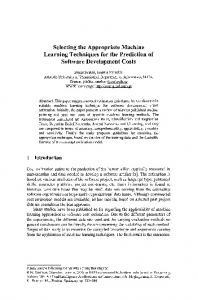
Initial thoughts and identifying the need, regarding the replacement of an existing system or indeed setting up a new service, should include informal discussions with local imaging and medical staff as to the likely benefit of purchasing a SPECT unit with CT capability. It is advantageous to contact other departments with experience of using SPECT/CT systems to discuss how their service has developed after the introduction of SPECT/CT as this would help direct your thinking to areas which you might not have otherwise considered. It is good practice to raise interest in the new technology and potential capability of a SPECT/CT system by informally inviting manufacturers to give presentations of their systems’ capabilities. Consequently, based upon a range of knowledge and experience, the staff responsible for the procurement process can start to begin to formulate informed ideas of what is available and whether the options would meet local operational and clinical demands (Fig. 6.1). Managers evaluating the cost/benefit of SPECT/CT systems are likely to require evidence of its advantages; they would also require financial information too. When considering this evaluation, the following points should be considered: • Clinical benefit, for example, increasing the diagnostic value, compared with SPECT alone, in terms of sensitivity and anatomical location of disease. This may have associated cost savings, which should be explained. For example, the surgical excision of parathyroid adenomata is a good example where (a) the precise anatomical location demonstrated by CT fusion can reduce the operation time and (b) the increased sensitivity to aberrant glands reduce the need to reoperate in the case of “missed” tumors and failed treatment. Also, the ability to correct images for SPECT attenuation losses can improve the diagnostic outcomes – and minimize false-positive and false-negative results – which often means further imaging and expense using alternative techniques. • Increased productivity/innovation – here, redundant SPECT/CT system time can be used for other purposes outside of normal working hours or as normal nuclear medicine workload allows, for instance: – – – – – – – –
CT colonography CT biopsy Conventional CT imaging Trauma imaging Coronary angiography CT coronary calcium scoring Research Combined cancer staging where nuclear medicine investigations can be combined with CT appointments and undertaken by the nuclear medicine staff on the hybrid system
6
113
Selecting an Appropriate SPECT/CT Scanner
Current imaging needs
Hybrid imaging functionality for image fusion
Planned SPECT/CT unit
Modified imaging possible with CT gantry
Stand alone CT use e.g. back-up unit
Fig. 6.1 Illustration of some considerations which can assist in specifying a SPECT/CT system to suit local needs in terms of patient flow, type of examinations envisaged, “future-proofing,” and formulating innovative ideas for imaging and treatment pathways
• Imaging service resilience – where smaller imaging departments can: – Plan to utilize the CT component during routine maintenance of the standalone CT scanner used for conventional radiology. – In exceptional cases, during unplanned downtime on the radiology CT unit, provide a “backup” service for emergency CT cases. The above possibilities can be seen as controversial in nuclear imaging terms, where there might be a perceived threat that the CT imaging might overwhelm the existing nuclear service. However, with effective leadership and suitable guidance for service delivery, this potential disadvantage can be turned into a strong advantage in terms of advancing nuclear imaging possibilities with image fusion and
114
J. MacDonald et al.
attenuation correction. Of course, the issue of service “creep” toward using CT as stand-alone, if allowed to, will more than likely apply to smaller imaging departments. Those nuclear imaging departments remote from radiology departments, or indeed where they are separate organizational entities, might benefit from collaborating on some of the above issues in order to procure the best imaging solution for the organization as a whole, bearing in mind the large financial outlay of a HP-CT unit and the possibility for redundant scanner time.
6.3
Formal Procurement
The process of deciding to proceed to plan the purchase of a large and expensive piece of medical equipment, especially one which emits ionizing radiation, has many stages (Fig. 6.2) and usually involves complex local issues together with national/international rules and regulations regarding the procurement process. This is especially true for the publically funded health-care services, such as the British National Health Service (NHS). Most organizations and countries have strict procedures and governmental regulations in the case of large capital investment involving public organizations [1–3]. Consideration also needs to be given to the disposal of old imaging equipment, as this in many countries is regulated too. At an early stage it is advisable to form a project team involving key individuals likely to have an influence on the procurement, installation, and commissioning of the new system or imaging suite. The project team is likely to consist of the following: a manger, imaging professionals, relevant clinicians, a medical physics expert, a finance representative, and a contracting manager. This team would then collaborate with other departments within the organization and with the “bidding” manufacturers and suppliers – as shown in Fig. 6.3. In the UK, NHS organizations follow the guidance of the Department of Health (DOH) in terms of the proper conduct for procuring equipment. The following guide represents which might be considered as a logical approach to procurement, based on this advice [4], and it might be generally applicable within other countries. It is advisable however to consult your own policies before proceeding. Devising a robust business case ensures that there is organizational commitment to deliver the planned change and that there is financial backing to progress with the procurement. The business case also provides a framework for progressing with the project, and it is finally used to monitor the project outcomes to determine whether they have been achieved as set against the business case [4]. The business case document should at the very least address the following [4]: (a) Strategic fit – description of the business need for purchasing a SPECT/CT system and how it will contribute to the business (imaging) strategy of the organization (b) Objectives – why it is needed now, key benefits of buying the new imaging system, and the critical success factors and how they will be monitored against the business case objectives
6
115
Selecting an Appropriate SPECT/CT Scanner
Project Team Conveened
Business Case/ Securing Funds
Exploring the Market/ Available Systems
Evalutation of Bids/ Systems on offer
Site Visits/System(s) Evaluation
Tendering Process/ Bids
Formulate and advertise the System Specification
Award Contract to Supply/Install
Installation Planning/ Building Work
Acceptance Testing
Identifying Need
Clinical Training Phase & ‘Sign-off’
Fig. 6.2 Suggested path towards procuring a SPECT/CT system
Fig. 6.3 Illustration of collaboration with other departments within the organization and with the “bidding” manufacturers and suppliers
Project team
Manufacturer/ installer/ ‘turn-key’ provider
Estates & facilities/ medical physics
(c) Options appraisal – high-level cost/benefit analysis appraising at least three options and identifying a preferred option with justification for this, for example: (i) (ii) (iii) (iv)
Doing nothing Purchasing a system without CT capability Purchasing a LP-CT system Purchasing a HP-CT system
116
J. MacDonald et al.
(d) Commercial aspects – this is usually required where there is an external procurement necessary and should include the following considerations: (i) Proposed sourcing options, with a rationale (ii) Key features of proposed commercial arrangements (e.g., contract terms, contract length, payment mechanisms, and performance incentives) (iii) Procurement approach/strategy, with a rationale (e) Affordability – to include statements of available funding, and rough estimates of the total cost of the project including future running costs, etc. (f) Achievability – high-level plan for achieving the desired outcome, with key milestones and major dependencies: (i) Outline contingency plans, for example, addressing failure to deliver service on time (ii) Major risks identified and outline plan for addressing them (iii) Provider’s plans for the same, as applicable, skills, and experience required (g) Source information – containing: project management plans, procurement documentation, high-level requirements, and the business strategy
6.4
Exploring the Market
At an informal initial stage, this can be useful in terms of examining the available SPECT/CT systems. This can be done by visiting manufacturer’s commercial websites, informally requesting marketing material, such as brochures and demonstration DVDs, visiting commercial exhibitions and having informal discussions with commercial representatives who can explain system feature. From this a system specification/requirement document can be drawn up, and the formal tendering document can be compiled ready for advertising in the required journals. A good specification should [5]: • State the requirement completely in a clearly concise and unambiguous manner. • Primarily focus on outputs (focusing on business deliverables rather than detailed service/system requirements). • Contain sufficient detail for potential suppliers to determine, and cost, the goods or services they will offer. • State the criteria for acceptance. • Provide equal opportunity for all potential suppliers to offer a product or service which satisfies the needs of the organization. A good specification should not [5]: • Over-specify requirements. • Contain features that directly or indirectly discriminate in favor of, or against, any supplier.
6
Selecting an Appropriate SPECT/CT Scanner
117
The European Union requires all tenders above a specified value to be advertised in the Official Journal of the European Union (OJEU), and other countries are likely to have similar systems for raising interest with the system vendors [1]. Once manufacturers express an interest from the tendering advertisement, expressions of interest are usually forwarded to the project team, even if this is indirectly via the organization’s procurement department. Tender response(s) evaluation can then take place when all the information is to hand from the available suppliers. There should be a robust process in place at this stage to evaluate the responses methodically to compare the responses to the tender requirements. This process will determine the preferred supplier. Consideration should be given to: value for money, project management capability of the supplier, service support (after-sales), engineering, or enabling costs. The evaluation method should be included in the business case, or at least agreed formally within the project team prior to this stage, so that the goods and services offered meet the required specification set out earlier. Some tenders can be eliminated as “not meeting the core specification” as set out in the advertised tendering document. These can be filtered out in terms of their capability and capacity to meet the requirement as well as their financial standing [5]. Prequalification questionnaires can be used to achieve this elimination, and will aid any legal process, by fully documenting the procurement decision-making process. The evaluation of any SPECT/CT system on offer will necessitate: • The careful and systematic evaluation of supplied technical documentation in support of any bid. • A technical evaluation of the equipment in a functional clinical setting (site visits) including operation of all system features (although sometimes not all features are available on one site, especially when medical equipment is new to the market, or certain features). • A formal appraisal of all desirable system features – which can be tabulated in spreadsheet form – later used to systematically compare available shortlisted scanners. • An equality impact assessment should also be undertaken to meet local policy. When system features are not available for demonstration or evaluation, it is important that any written contractual agreement details the precise specification and operation required and that the supplied equipment will be constructed and commissioned to fully meet the need, and this clause should be linked to a payment model, for example, some retention of payment, until fully commissioned to specification [5]. The multidisciplinary project team should individually evaluate each system in terms of their own expertise, using an evaluation matrix, and any questions requiring responses from the supplier should be addressed at a single point of contact. Table 6.1 shows an example of an evaluation matrix where scores for features and functionality can be summed. This ensures that there is a good audit trail should problems arise later if a system is installed not quite meeting the expectation of the
118
J. MacDonald et al.
Table 6.1 SPECT/diagnostic CT procurement reference site evaluation matrix Reference site details Supplier System A System B Location No. 1 Comments, e.g., on type of center and type or work performed on unit
Location No. 2 Comments, e.g., on type of center and type of work performed on unit
Installation and commissioning support Quality (adequacy) of application specialist package Advice available from commissioning engineer? Anticipated installation problems? Will CT/gamma camera work independently? Overall confidence in system delivering anticipated functionality and reliability?> Subtotal: Gamma camera imaging system General ease of positioning camera heads (weighted score) Gamma camera system overall spec. (tech) Whole body positioning SPECT positioning – body SPECT positioning – brain SPECT positioning – cardiac Ease of “starting” a dynamic acquisition single handed Closest distance heads can come together Ease of positioning transmission phantom, e.g., sentinel node imaging Arm rests provided for WB positioning Arm rests provided for SPECT Head rest supplied for brain SPECT Interlocks for touching patients Crash avoidance system (heads/other equip.)
Address A Factory demonstration
Address B Private General Diagnostic center with wide range of investigations using CT/SPECT
Private facility using “x” system only, no CT
NHS Physics run department with full Nuc. Med but limited diagnostic CT usage
4
5
0
5
5 3
5 4
4
4
16
23
15
20
3.5
4
4 3.5 3 4 4
3.5 4 4 3.5 4.5
4
4
3
5
5
5
5 5 3.5 3.5
5 5 4 4
6
119
Selecting an Appropriate SPECT/CT Scanner
Table 6.1 (continued) Reference site details Supplier Termination bell (can it be silenced) Visible cue for scan termination (patient) Child-friendly features Suitability for imaging children overall Erect positioning in chair, e.g., renograms Able to image on patient bed? Adequate patient weight limit? Field of view size for large patients Collimator (time to change) Collimator exchange automation
System A
System B
0 3
0 4
3 17.5
4 20
3.5
5
3 5 5 3 10
5 5 5 4.5 20
Scores 0–5 (0 = no response, 1 = very poor, 2 = poor, 3 = good, 4 = very good, 5 = excellent)
project team [5]. Individual team members should note at this stage the sensitive nature of the information being evaluated, and they should take care to ensure that this stage is confidential. This should guard against releasing commercially sensitive information that might prejudice the whole procurement process. The project team should also consider the installation and commissioning process as part of the evaluation, including the environment in which the SPECT/CT scanner will be sited. The ability of the scanner to function according to specification might be adversely affected should this part of the process be neglected. After final consideration, it is sometimes beneficial to have private meetings with each of the companies tendering – in order that final negotiation can take place regarding supplied features within the cost quoted – and to clarify on any ambiguous areas of the procurement process in relation to each system manufacturer’s/ supplier’s goods and services. The project team will then be in a position to award the contract, with the assistance of procurement professionals within the organization, to the preferred supplier having met most, if not all, of the specification requirements initially set out. Usually this will involve issuing an agreement and cover letter.
6.5
Installation Planning and Building Work
This is often provided as a “turnkey” service by equipment suppliers or can be inhouse by hospital estates and facilities department. The essential requirements of a facility to house a SEPCT/CT scanner are discussed in Chap. 7 in detail. However, at this juncture, it is necessary to consider the environment housing the new scanner as being part of the commissioned service, especially if a “turnkey” provider has
120
J. MacDonald et al.
installed supporting facilities – as these need careful acceptance checking for compliance with the specification. Local estates and facilities staff can assist in ensuring that the terms of the contract have been met in this respect. With respect to accepting the new SPECT/CT scanner into use and to ensure that the terms of the procurement are met, the following points need to be evaluated: • That the equipment supplied is to specification and is the latest model with latest version of software installed. • That there is no apparent damage. • That specified accessories are available. • That any “software packages” are installed and fully functional. • The system should have local electrical safety checks made to ensure compliance with local legislation. Thereafter, the following needs to be considered: • Medical Physics Quality Assurance Acceptance Testing: – Ensuring the gamma cameras perform to specification – Ensuring the CT scanner and X-ray components perform to specification and within local legal constrains – Checks to ensure that the fusion alignment between the CT and gamma camera is to specification • • • •
Radiation Risk assessments should be made – according to local regulation Maintaining records of the above Ongoing system maintenance contracts That equipment documentation is available together with detailed operating instructions and reference material
Staff training on the new SPECT/CT scanner will need to include formal training of local staff by application specialists, and if this training is adequate, then this should be documented as evidence of competency to use a piece of medical equipment. End users need to be aware of the normal operation of the SPECT/CT system in order to use it safely and effectively. Training should cover [1]: • Any limitations on use • How to fit accessories and to be aware of how they may increase or limit the use of the device • How to use any controls appropriately • The meaning of any displays, indicators, alarms, etc., and how to respond to them • Requirements for maintenance and decontamination, including cleaning • Recognize when the device is not working properly and know what to do about it • Understanding the known pitfalls in the use of the device, including those identified in safety advice from government agencies, manufacturers, and other relevant bodies • Understanding the importance of reporting device-related adverse incidents to national safety agencies sponsored by government
6
Selecting an Appropriate SPECT/CT Scanner
121
Finally, the procurement process is likely to be a generalized process internationally, as local legislation is likely to vary in terms of detail. However, the above overview of the process should give a basic understanding of the complexity of the procurement process, some of its pitfalls, and serve to illustrate the need to involve professionals of various professional groups at appropriate stages, to ensure the best outcome.
6.6
Hardware Designs of Modern SPECT/CT Systems
Prior to the introduction of dedicated SPECT/CT systems within clinical practice, a number of techniques were available for the correction of attenuation and/or image registration. In the late 1970s, software-based attenuation correction algorithms began to emerge within medical imaging, as computers became more powerful. Chang’s [6] attenuation correction provided a software-based approach to correcting for the effects of attenuation within a relatively uniform field of density (Fig. 6.4). In the 1980s, increased clinical interest in corrective algorithms and image fusion techniques was again possible due to the provision of powerful dedicated computer systems. However, motion artifacts impacted upon software-based image fusion approaches, which imported reconstructed data from different imaging systems. This was especially the case for clinical areas such as the thorax, abdomen, head, and neck [7]. The use of external fiducial markers has also been utilized within clinical imaging in order to align anatomical and physiological data sets, using relatively basic software [8]. The availability of specialist’s three-dimensional elastic transformational/nonlinear warping has emerged within some clinical department
Fig. 6.4 External transmission source array and projected photon flux, which is centered around the myocardium
122
J. MacDonald et al.
over the last 10 years, providing a potential solution to the effects of breathing motion artifacts during the registration of two different data sets [9]. Combining data sets from different imaging systems is now considered to be a defined aspect of clinical practice, which is still evolving in many different clinical areas [10]. Published evidence indicates that the level of registration accuracy between data sets (thorax and abdomen) acquired on separate imaging systems is approximately 5–7 mm [9]. Software-based registration of anatomical and physiological data still has an important role in accurately correcting for misregistration issues and for corrective approaches to registration artifacts in the thorax, such as respiratory motion [11].
6.7
External Radionuclide Transmission-Based Correction Systems
The emergence of external radionuclide sources in order to perform attenuation correction became a clinical option in the late 1980s and early 1990s. A range of approaches were adopted, involving the use of moving or stationary radioactive rod sources, configured to provide a transmission map and apply an attenuation coefficient to the specific emission data. Gadolinium-153 was most commonly used within a number of systems [12], which has a physical half-life of 242 days, with two main useful photopeaks of 97 and 103 keV respectfully. Demonstrates a typical external transmission-based correction system, using an array of line profile sources in order to provide attenuation coefficient data, which is then applied to the emission data set. A number of commercial designs provided the user with an option to perform attenuation correction within myocardial perfusion imaging examinations. Simultaneous emission and transmission imaging is possible using an externalbased radionuclide system; however, consideration had to be factored in for the use of thallium-201, where sequential imaging was advised due to potential crossover of gadolinium-153 into the upper energy window of thallium-201. Another limitation of external transmission-based radionuclide correction systems related to the fact that validated use was purely for the purpose of myocardial perfusion imaging. Although transmission maps provided some anatomical information, the spatial resolution was poor (Fig. 6.5) and the photon flux was inferior in comparison to modern CT data. Issues relating to mechanical misalignment, malfunction of the radionuclide source housing, and ineffective count density values with obese patients have been reported with external transmission source systems [12]. Truncation artifacts are also a potential issue with radionuclide-based transmission sources, especially as size of the patient’s body increases. Additional corrective techniques may be employed (i.e., energy window crosstalk correction, scatter correction) to ensure data quality is not affected. It is argued that scatter correction should also be employed in addition to attenuation correction, in order to avoid overestimation of certain areas during myocardial perfusion examinations [13].
6
Selecting an Appropriate SPECT/CT Scanner
123
Fig. 6.5 Example reconstructed transmission maps of the lungs, produced from gadolinium-153 sources
Dedicated cardiac gamma cameras are utilized within modern clinical practice, with the option of external radionuclide-based transmission imaging for attenuation correction. Such systems provide a robust clinical service, and the patient dosimetry associated with the provision of attenuation correction data from the radionuclide transmission sources is considerably less than standard multislice CT protocols [14]. However, the introduction of low-resolution CT scanning protocols within hybrid SPECT/CT systems has reduced the effective dose considerably [15]. Most clinical nuclear medicine departments have replaced their radionuclide-based transmission systems with CT-based hybrid units, due mainly to the extended scope of potential clinical practice (i.e., not just cardiac work), higher photon flux, and localization/diagnostic imaging capabilities.
6.8
First-Generation CT-Based Systems
Initial research around the potential use of a combined SPECT/CT system was conducted in San Francisco by Dr. Hasegawa and colleagues [16] and involved the use of high-purity germanium detectors to simultaneously acquire X-rays (40–100 keV) and gamma rays (140 keV). Unfortunately, this system required a total examination
124
J. MacDonald et al.
time of between 3 and 4 h and was therefore impractical for routine clinical use. The concept of a single imaging environment, which utilized an X-ray-based detector system, in addition to gamma ray detection, was further refined to create a dedicated environment, which included a single-headed gamma camera and a single-slice CT unit. Acquisition times were quicker than the previous prototype, and this approach provided a true representation of anatomical localization and attenuation correction capabilities. The use of an X-ray source in the form of a CT-based unit provides attenuation coefficient data, which is rich in photon flux (lower image noise), compared to other transmission-based methods and provides an option for higher quality anatomical data [15]. Initial hybrid SPECT/CT gamma cameras utilized a low-end-resolution CT unit, which provides an axial resolution of 10 mm [11], and the X-ray tube and detector configuration are located on the same gantry as the detector heads of the gamma camera (Fig. 6.6). Unlike the initial approach taken by Hasegawa and colleagues [16], the SPECT and CT imaging is not simultaneous, with the CT examination being conducted after the SPECT procedure. A four-slice version of the GE Hawkeye provides an axial resolution of 1 cm but still utilizes the same gantry as the gamma camera detectors. Due to the physical geometry of the first-generation system, the rotation speed of the CT unit is limited to below 2.8 revolutions per minute [17], utilizing slip-ring technology within the gantry. Such low-resolution images are useful for attenuation correction, spatial localization, and fusion with SPECT data, but cannot substitute high-resolution diagnostic CT [18]. The acquisition time for 40 cm field-of-view coverage is 12 min with a first-generation GE Hawkeye system; however, the acquisition time is quicker for the 4-slice GE Hawkeye system. The approximate patient dose from the CT procedure is also considerably lower (20 times less) than a dedicated CT system [11]. In summary, an entry-level SPECT/CT system offers a gateway to the provision of a fundamental hybrid imaging service and an opportunity to incorporate new techniques within a nuclear medicine department. The introduction of SPECT/CT has redefined the layout of traditional nuclear medicine departments, with the addition of lead shielding required for the protection of operators during the CT examinations. Figure 6.7 demonstrates a typical setup for a first-generation SPECT/CT system (GE Hawkeye), with the inclusion of a secondary radiation protection barrier for the operator. Although the introduction of a secondary radiation barrier presents new ways of working for the traditional practitioner in nuclear medicine, the acquisition and possible processing workstations are now positioned behind a screen, which is less visible to patients. Certain acquisition operations are now also possible from behind the protective screen (e.g., commencement of examinations), which may minimize personal radiation dose from the patient during conventional nuclear medicine and/or hybrid examinations. However, consideration should be given to the impact upon future working practice of staff within this new environment, particularly when undertaking certain patient examinations [19, 20]. Within multisystem departments, the introduction of a SPECT/CT unit may require reorganization of available space, particularly if an open design is present.
6
Selecting an Appropriate SPECT/CT Scanner
125
Fig. 6.6 GE Hawkeye SPECT/CT system, with integrated X-ray unit, consisting of a low-output X-ray tube and cadmium tungstate detectors
Fig. 6.7 Shielding area for operator within a SPECT/CT environment
Figure 6.8 demonstrates an example multisystem departmental layout, and the use of retractable/movable lead screens is utilized during SPECT/CT examinations. The SPECT/CT system incorporated within Fig. 6.8 is a GE Hawkeye, which has a low X-ray tube output of between 1 and 2.5 mA. Consideration should however be given to operators working in other parts of an open space department, to ensure they are not at risk of unnecessary exposure during a hybrid imaging examination.
126
J. MacDonald et al.
Superintendents office
Spect/CT
Fig. 6.8 Example layout of a multisystem department, demonstrating configuration of operating areas and available floor space. The space required for a GE Hawkeye and Hawkeye 4 is similar to a conventional gamma camera SPECT system (14 × 16 ft) [11]
6.9
Modern SPECT/CT Systems
Modern hardware engineering developments have advanced at a rapid pace over the last 5 years, and the inclusion of a dedicated high-specification CT unit within an existing gamma camera is beginning to redefine patient treatment and subsequent management [13]. Multislice CT units, coupled to modern gamma camera units, also utilize clinical features such as laser positioning markers and semirigid imaging pallets, to ensure accurate co-registration of emission and transmission data, for the purposes of image fusion applications. The availability of separate gantry systems (Fig. 6.9) overcomes the relatively inferior resolution and slower CT acquisition speed, which is associated with first-generation SPECT/CT systems. This has however created the need for additional cooling systems for the CT components, which is either air or water controlled and adds increased noise levels within the imaging environment, compared with first-generation systems.
6
Selecting an Appropriate SPECT/CT Scanner
127 Persistence monitor
Rear bed support
CT system
Gamma camera detectors
Patient imaging pallet
Fig. 6.9 Overhead view of a modern SPECT/CT system, demonstrating the separate imaging components within one physical environment
In addition, greater consideration is now required for the accurate acquisition of CT data, as it will be performed quicker than conventional first-generation systems, which may lead to respiratory motion artifacts. SPECT/CT systems with 64-slice technology are now commercially available, providing an extended scope of clinical examinations, such as cardiac CT and stand-alone, contrast-enhanced CT techniques. The main advantages of multislice CT units include shorter scan times, extended scan ranges, and improved longitudinal resolution capabilities. The operator also has a choice of how the CT data is acquired (i.e., in terms of spatial resolution), with various detector array combinations possible with higher multislice CT units [11]. Recently, the emergence of a SPECT/CT system with a flat panel X-ray detector has been introduced within clinical practice (Fig. 6.10). The Philips BrightView system offers an ability to acquire coplanar and SPECT/CT and utilizes a digital amorphous silicon detector panel, which is retractable. Although the CT unit is on the same gantry as the gamma camera detectors, this system is capable of performing 5 rotations per minute, which is considerably quicker than other systems with a similar geometry design. The floor space required for a multislice SPECT/ CT unit is considerably bigger than a first-generation system, with 15 × 24 ft being documented by some manufacturers. This is considerably larger if you include a separate operator’s console as well. The floor loading space should also be
128
J. MacDonald et al.
Fig. 6.10 Philips BrightView XCT system, featuring a retractable flat panel X-ray detector system
Fig. 6.11 Installation of floor plates to preserve the alignment of the patient imaging pallet to the gantry
6
Selecting an Appropriate SPECT/CT Scanner
129
assessed, as the weight of a multislice SPECT/CT system is considerably heavier than a GE Hawkeye unit, almost double in some instances [11]. In some departments, the installation of floor plates (Fig. 6.11) has been undertaken to ensure the registration between the patient imaging system and gantry is accurate over time.
6.10
6.10.1
Additional Considerations for Introducing a New SPECT/ CT System Patient Weight Capacity of Patient Imaging Pallet (Bed)
Consideration for the maximum weight of the imaging pallet needs to be factored, especially if the patient is going to have a CT examination. Although all SPECT/CT systems have a rear bed support (Fig. 6.8), there is potential for image sag between the emission and transmission data sets with obese patients. Most SPECT/CT systems will guarantee weights up to 200 kg (440 lb), with a pallet deflection (image sag) of less than 2 mm at 90 kg.
6.10.2
Minimum Height of the Patient Imaging Pallet (Bed)
Ideally, the minimal height of the patient imaging pallet should be low enough to accommodate wheelchair patients but also high enough to transfer patients safely from a bed/stretcher.
6.10.3
Travel Length of the Patient Imaging Pallet (Bed)
Typically, this will be in the region of 200 cm, to allow multiple bed positions to be fused together within SPECT/CT examinations. First-generation SPECT/CT systems had limited z-axis coverage, due to the design of the hybrid imaging unit. However, the introduction of integral bed and CT gantry designs has created additional coverage and flexibility for multi-bed SPECT/CT examinations.
6.10.4 Auto Contour and Positioning Optimization All modern SPECT/CT systems should offer an auto contouring facility for SPECT examinations and the ability to plan the CT examination from the SPECT data (often referred to as “guided CT”).
130
J. MacDonald et al.
6.10.5 Automated Collimator Configuration Having a wide range of collimators to accompany the purchase of a new SPECT/CT system may be inevitable, especially if the range of examinations increases due to the availability of new imaging procedures (e.g., In111, I131). Some SPECT/CT systems offer a semiautomated form of collimator exchange process, which reduces the amount of manual handling associated with this task. However, the positioning of collimator carts within a bust nuclear medicine department needs considerations, especially if they contain high energy collimators.
6.10.6
Type of CT Unit
Some manufacturers offer a range of CT units for use within a SPECT/CT system. Typical entry-level SPECT/CT systems will provide CT data with an axial resolution of between 3 and 5 mm, whereas higher specification units will generate an isotropic resolution (e.g., 0.33, 0.63 mm) output.
6.10.7
CT Tube Loading
Initial SPECT/CT systems only offered tube loadings in the region of 10 mA; however, modern mutlislice CT systems offer tube loadings of between 30 and 240 mA, with higher specification systems providing up to 345 mA.
6.10.8
Dose Modulation
All modern (SPECT/)CT systems will incorporate dose modulation, in order to minimize patient dose from the CT examination.
6.10.9
Laser Positioning Lights
Laser lights aid in the positioning of patients for hybrid and stand-alone CT procedures.
6.10.10 Automated Routine Quality Control Mode Some systems now offer the ability for automated routine/daily quality control checks, with an integrated point source. This permits the daily quality control checks to be performed prior to the commencement of the working day.
6
Selecting an Appropriate SPECT/CT Scanner
131
Fig. 6.12 Variable geometry of gamma camera heads on a modern SPECT/CT system, reducing the “closed” space during the CT procedure
6.10.11
Size of CT Patient Bore
Consideration for the size of the CT aperture is needed, in order to identify any potential truncation artifacts from large patients undergoing a SPECT/CT procedure. Typical gantry aperture sizes within SPECT/CT systems are in the region of 70 cm, with a useful scan field of 50 cm.
6.10.12
Degree of Flexibility with the Gamma Camera Detectors
The greater the degree of flexibility with the gamma camera heads, the potential for patient compliance will become apparent. In addition, some equipment manufacturers position the gamma camera detectors in to the “L” mode (i.e., cardiac imaging) underneath the patient bed during the CT acquisition, in order to provide the appearance of open space for the patient (Fig. 6.12).
6.10.13
Integration of Flat Panel Imaging Pallet
The ability to fix a flat carbon fiber pallet to an existing patient imaging system provides an imaging environment which offers the capability to acquire data for radiotherapy planning and/or dosimetry purposes.
132
6.10.14
J. MacDonald et al.
Resolution Recovery Hardware/Software
Manufacturers now offer a new generation of focused collimators which offer the prospect of reduced scanning time for certain examinations. Coupled with advanced resolution reconstruction software algorithms, clinical departments are revisiting their traditional patient workflow patterns and introducing new accompanying imaging techniques, such as calcium scoring.
6.10.15
Flexibility of CT Acquisition Parameters
Modern SPECT/CT systems offer the operator the ability to acquire the CT data at various levels of resolution/quality.
6.10.16
CT Processing Parameters
Equally, there are also a number of processing parameters associated with the acquired CT data, which can be employed by the operator.
6.10.17
Integrated ECG Hardware Port and Output Display
The ability to acquire an ECG signal during cardiac examinations should be relatively straightforward. An integrated ECG port on the SPECT/CT unit (Fig. 6.13) and a display on the persistence scope provide the operator with flexible working environment.
6.10.18
Communication and Patient Monitoring Aids
A voice intercom and patient monitoring camera can provide additional monitoring during the CT examination. In addition, the use of visible lights for patients can provide an indication when the CT examination is about to begin.
6.10.19
Patient Positioning Supports
The use of a dedicated head support during neurological examination provides support/immobilization for the patient, close contact for the gamma camera detector heads, and an isocentric point of reference for the CT examination, if being performed.
6
Selecting an Appropriate SPECT/CT Scanner
133
Fig. 6.13 Integrated ECG port on the patient imaging pallet allows seamless acquisition of cardiac gating data during myocardial perfusion examinations
Most manufacturers adopt the use of carbon fiber within the construction of imaging beds and head supports. The use of carbon fiber represents a low atomic number material, which will absorb less than 10 % of gamma energy (at 140 keV).
6.10.20
Environmental Noise
The use of a multislice CT unit requires either additional air or a water cooler in order to maintain an operating temperature for the CT components.
6.11
Conclusion
The financial cost of implementing a SPECT/CT hybrid imaging system needs to be assessed early on in the procurement process as possible. Additional work will need to be performed on your existing examination room (e.g., addition of a lead glass screen/separate operator’s console) and ensuring there is enough space for the unit. In addition, the maintenance contract of the hybrid imaging unit may be slightly higher than a conventional gamma camera, to include the CT unit [19].
134
6.12
J. MacDonald et al.
Software Considerations for SPECT/CT
6.12.1 Acquisition Software SPECT/CT systems have acquisition setup software that allows various parameters to be specified for both nuclear medicine and CT imaging. For SPECT/CT specifically, there are several options for defining how imaging is carried out, and these need to be carefully considered when purchasing a system. Acquisition protocols can typically be set up to acquire either the SPECT followed by the CT or vice versa. In the first case, systems may then allow the scope of the CT to be determined from the SPECT images. This would be useful, for example, if a SPECT scan had identified a small focus of activity which would benefit from being fused with a CT image; the CT field of view could then be defined to encompass just the extent of the activity, thereby reducing CT exposure to the patient. This is termed SPECT-guided CT. Alternatively, it may be possible to acquire the CT first. In this instance, a topogram or scout view would typically be acquired, from which the area to perform CT on is determined. This would then be followed by a SPECT image covering the same volume. In terms of reducing patient exposure, some systems can perform a low-dose CT scan for the purposes of attenuation correction and SPECT/CT fusion, and this may be an advantage if fully diagnostic CT is not required. The availability of diagnostic quality CT on a SPECT/CT system may, however, be beneficial in obviating the need to carry out a separate CT scan if clinically indicated. These systems should also be capable of carrying out low-dose CT for the purposes of attenuation correction, for which high-resolution CT is not necessary. Most SPECT/CT systems will have automatic dose-reduction algorithms, which should be evaluated during the tendering process.
6.12.2
Processing Software
Processing software will include tomographic reconstruction of the SPECT and CT data. Options for SPECT reconstruction are likely to include filtered back projection (FBP), with a range of suitable filters, and iterative techniques such as ordered subset expectation maximization (OSEM). Processing systems should allow different types of pre- and post-filters and the ability to vary the parameters to control the extent and magnitude of smoothing before and/or after reconstruction. Most systems also allow some form of resolution recovery, which can correct for the lost of spatial resolution with distance from the gamma camera face and is purported to give equivalent image quality with a reduced number of counts. This allows reduction of imaging time and/ or activity (and hence radiation dose to the patient). Scatter correction is also generally an option within SPECT reconstruction for modern-day systems.
6
Selecting an Appropriate SPECT/CT Scanner
135
Correction for the attenuation of gamma rays within the body is important in some applications and comes as standard on most SPECT systems. Attenuation correction takes into account the differing amounts of attenuation of gamma rays as they traverse the body. This attenuation will vary with projection angle, as different anatomical structures will obstruct the gamma rays depending on the direction of the path between their origin and the gamma camera. Attenuation correction can be performed using simple geometric assumptions, for example, a uniform cylinder, but the availability of the CT on a SPECT/CT system allows this to be performed much more accurately since the CT images give an accurate anatomical map. The accuracy of attenuation correction depends on having proper registration between the two modalities. This is essential as nonaligned images will lead to errors in the calculated attenuation factors which, in turn, can cause artifacts in the reconstructed images. The system display should allow corrected and non-corrected images to be displayed side by side to indicate the presence of such artifacts. As the SPECT and CT procedures are not performed simultaneously or in the same bed position, misregistration may occur for two reasons: (i) a systematic error in the positioning offset between the SPECT and the CT and (ii) patient movement between the SPECT and CT imaging procedures. The former is calibrated at installation and should be checked periodically (see Sect. 4.5). The latter will be somewhat patient dependent but may be reduced through adequate explanation of the process to the patient beforehand and proper patient supervision throughout the whole imaging process. Although (i) may not be an issue, it is essential that the processing software allows manual registration of the SPECT and CT data sets to overcome situations where the patient has moved between studies. The ease of use of such software should be evaluated as part of the tendering process. Properly aligned SPECT and CT data sets can then be used to allow accurate attenuation correction. Typically, software will calculate an attenuation map from the CT slices. This is a set of slices of the same resolution as the SPECT data with values representing attenuation coefficients that are derived from the CT number. The attenuation map is then used in the iterative reconstruction algorithm. Normally, this is an automatic part of the processing with little or no control other than to switch it on or off. SPECT/CT image fusion display is another important part of the processing software. Typically, this will allow SPECT and CT images to be overlaid. It is useful if the software allows control of the blending or weighting between the two data sets from one extreme, that is, 100 % CT 0 % SPECT, and to the other, that is, 0 % CT 100 % SPECT. Color scales or lookup tables (LUTs) are also very important when trying to assess SPECT/CT fused images. CT is typically displayed in a linear grey scale, whereas the SPECT data is displayed in color. Figure 6.14 shows a SPECT-CT fusion display with weightings: (a) 100 % CT, (b) 70 % CT 30 % NM, (c) 50 % CT 50 % NM, and (d) 70 % CT 30 % NM. Some systems allow other display options, such as count contours, which can also be useful in certain situations, as shown in Fig. 6.14d.
136
a
J. MacDonald et al.
b
c
d
e
Fig. 6.14 (a–e) SPECT-CT fusion display with weightings: (a) 100 % CT, (b) 70 % CT 30 % NM, (c) 50 % CT 50 % NM, and (d) 70 % CT 30 % NM (e) Count contour type display
Tools, such as triangulation cursors and slice scrolling, are generally available to simplify localization of lesions. Some systems may also offer 3D image fusion, which may be useful in certain situations. Archiving of images is another area of software that needs to be considered. This can be done via local backup media such as optical disks or DVDs and/or through a picture archiving and communication system (PACS). The latter allows images to be stored on a central server, together with other images from other modalities and other data such as clinical reports and medical photographs. Images stored on PACS are typically in Digital Imaging and Communications in Medicine (DICOM) format, which is a medical imaging standard allowing images to be transferred between and viewed by any DICOM-compliant software. Options such as automatic archiving, for example, overnight, and the types of images and data that can be stored, should be carefully considered.
6.13
Quality Control Tests for SPECT/CT
Aside from the usual range of quality control tests that are needed to maintain the separate gamma camera and CT elements of the SPECT-CT scanner, the combination requires additional testing in two respects – registration and accuracy of attenuation correction.
6.14
Registration, or Alignment, Between the Two Modalities
Precise registration is essential in achieving accurate attenuation correction and SPECT/CT image fusion. There are two elements that affect the accuracy of SPECT-CT registration: (a) Patient movement between the SPECT and CT imaging procedures This includes not only change of position of the patient between scans but also involuntary movement due to respiration, cardiac motion, etc. Quality control on a per-patient basis must be carried out using appropriate system software that
6
Selecting an Appropriate SPECT/CT Scanner
137
Fig. 6.15 SPECT-CT alignment phantom
allows clear assessment of SPECT/CT registration and the ability to perform a manual reregistration if necessary. (b) The mechanical offset between the SPECT and CT gantry positions This is calibrated by the manufacturer’s engineers at installation of the system, thereby providing an automatic means of correction thereafter. This needs to be checked on a periodic basis as part of the system’s routine quality control and immediately following any gantry adjustments. The frequency of testing depends on the stability of the system, and the European Association of Nuclear Medicine (EANM) Physics Committee have proposed that this be done at least monthly [21]. This is achieved by using a test object which has structures that are visible on both SPECT and CT; for example, the phantom shown in Fig. 6.15 could be used. This has hollow spheres which can be filled with a solution of Tc99m, allowing them to be visualized on the gamma camera as well as the CT. A SPECT/CT scan is then carried out and the image fusion software is used to ensure accurate alignment. Figure 6.16 shows some of the resulting fused images for a system with good registration between the two modalities. The colored nuclear medicine images clearly show uptake in the sphere and cylinder volumes, the boundaries of which are highlighted with the CT.
138
J. MacDonald et al.
Fig. 6.16 Example of good SPECT-CT registration
Fig. 6.17 SPECT-CT alignment check setup for GE Hawkeye
Apart from such generic phantoms, manufacturers generally supply specialized test objects for the purpose of testing SPECT/CT alignment, which can also be used to recalibrate the offsets should it be necessary. These test objects vary from one
6
Selecting an Appropriate SPECT/CT Scanner
139
manufacturer to another; some use an array of small gadolinium-153 (Gd-153) disks mounted on a frame. The Gd-153 sources emit gamma rays that are detected and imaged by the gamma camera and that are dense enough to show on the CT images. Others use syringes filled with Tc99m solution mounted in a foam structure (as shown in Fig. 6.17) or small vials which are filled with a Tc99m solution mixed with CT contrast media. There are advantages and disadvantages to these methods which need to be considered when purchasing a system. For example, test objects that utilize long-lived, sealed sources, such as Gd-153, will need to have those sources replaced several times during the lifetime of the camera, since the half-life of this radionuclide is around 8 months. The resupply and radioactive waste disposal of these sources will incur a cost each time this is done, and this needs to be borne in mind when costing the system. Conversely, although the methods that rely on containers that are filled with Tc99m solutions do not have that disadvantage, they do require significantly more time on each occasion to set up and use. It is largely then a balance between cost and convenience.
6.15
Accuracy of Attenuation Correction (AC)
Proper correction of attenuation will produce images with accurate reproduction of the radionuclide distribution. This is especially important when quantification of uptake is required. AC is commonly used in myocardial perfusion imaging where it can correct for differences in attenuation, which is particularly problematic in the anterior wall in women with large breasts and in the inferior wall for obese men. Accuracy of AC depends on SPECT-CT registration (see (i)) and on the translation of CT data to an attenuation map. This latter aspect relies on attenuation coefficients derived from CT numbers. Accuracy of AC is not normally assessed by manufacturers at installation, and test objects are not normally supplied to enable this to be tested. Third-party test objects, however, are available, such as those in Fig. 6.15. This phantom has 2 refillable cylindrical chambers of the same diameter, one outside the phantom and the other inside. Both can be filled with a Tc99m solution. The activity in the inside phantom is subject to variable attenuation from water, liquid bone, and air. A SPECT-CT acquisition is performed and the SPECT data attenuation corrected. A profile drawn through the center of the cylinders on a sagittal or coronal slice will indicate whether AC is correcting properly. Figure 6.18 shows example profiles of non-AC vs. AC overlaid on a sagittal CT slice to show the structures within the phantom. In this example, the AC data is a significant improvement over the non-AC but has overcorrected by about 20 %. It is quite possible to test AC using locally constructed test objects, for example, using Tc99m-filled syringes inside and outside different attenuating media.
140
J. MacDonald et al.
NoAC AC
Fig. 6.18 Assessment of attenuation correction results
6.16
Emerging Techniques for SPECT/CT
The emergence of SPECT/CT systems within the nuclear medicine environment has provided the opportunity to perform new techniques and interprofessional working opportunities [22, 23]. Modern multislice computed tomography (MSCT) technology coupled with state-of-the-art photon detection systems has provided a realistic solution to attenuation and registration issues [24]. Hybrid SPECT/CT systems are now accessible in most nuclear medicine departments, along with associated sophisticated software to correct for the effects of misregistration and motion artifacts. The integration and clinical use of CT within a SPECT imaging environment has been slower than PET/CT, but over the last 10 years, this balance has been addressed, with modern multislice SPECT/CT units now having the diagnostic capability to provide a high level of anatomical information, which is considered important for the management of patient pathways [25]. Over several years the reemergence of established nuclear medicine techniques, involving radioisotopes such as gallium (Ga67) citrate, indium (In111) octreotide, iodine (I131), and thallium (Tl-201) chloride, has been documented [26–29]. This has led to a steady resurgence of SPECT/ CT techniques within the nuclear medicine department [25] and a greater level of diagnostic confidence and overall involvement in the patient management. Clinical areas where SPECT/CT is emerging as a “front-line” technique include: Benign/malignant skeletal tumors: The use of SPECT/CT minimizes the number of equivocal findings normally associated with planar imaging and is beginning to be
6
Selecting an Appropriate SPECT/CT Scanner
141
utilized as a whole body protocol to characterize indeterminate lesions in patients with known malignancies [30]. Sentinel node lymphoscintigraphy: The use of SPECT/CT for sentinel lymph node mapping is an area, which has brought together health-care professionals and begun to transform clinical practice. SPECT/CT techniques improve the accuracy of anatomical localization of the sentinel nodes, especially if they are close to the injection site [31]. Preoperative assessment of parathyroid adenomas: The use of SPECT/CT increases the overall sensitivity and specificity of parathyroid adenomas and also aids in the localization of potential ectopic and/or multiple adenomas [32]. The inclusion of nuclear medicine practitioners in the preoperative assessment of parathyroid adenomas, working in conjunction with other professional groups, has a positive impact on workforce dynamics. Neuroendocrine tumors: The value of SPECT/CT and the use of radiopharmaceuticals such as In111 octreotide in the detection of neuroendocrine tumors (NETs) are well documented [33–35]. The use of SPECT/CT as part of the imaging technique for the detection of NETs has been reported to change the overall management of patients in over one-third of cases [36] and impact on the type of therapeutic treatment [37]. Figure 6.19 provides an example of the clinical value of In111 octreotide SPECT/CT imaging. Selective internal radiation therapy (SIRT): The use of SPECT/CT can be useful in the pre- and post-therapy imaging of SIRT techniques, such as yttrium-90, which is used for the treatment of non-resectable liver tumors. Integration of coronary angiography and calcium scoring CT: The emergence of multislice diagnostic CT units with low-dose acquisition protocols and prospective ECG triggering offers a realistic opportunity to perform hybrid imaging techniques on different risk groups of patients [38]. Using the latest iterative reconstruction algorithms for SPECT myocardial perfusion imaging (and a reduced radioactivity dose) and a low-dose CTA results in the production of hybrid images with a radiation dose of less than 3 mSv [39].
6.17
Changes to Working Practice
Referrals for examinations requiring new isotopes/radiopharmaceuticals may require modifications to various aspects of working practice, including the development of new clinical protocols, which may encompass anatomical-based imaging. Combined SPECT/CT procedures should be chosen on an individual basis, justified, and reflect clinical need [40]. Decisions should be made related to the appropriate use of CT for the specific examination being performed. The use of diagnostic CT within a SPECT/ CT examination may increase the overall patient dose by up to 14 mSv [41]. Use of low-dose CT may reduce the additional patient dose to a range of 1–4 mSv [40] and may be useful for attenuation correction or localization purposes. Modern technology and resolution-based software methods have provided greater access to hybrid imaging techniques within most nuclear medicine departments. Such developments have also placed greater responsibility on the practitioner to engage with new imaging and processing protocols and possible use of ionic contrast media
142
J. MacDonald et al.
a
b
Fig. 6.19 (a) SPECT/CT of patient with known diagnosis of metastatic carcinoid, with mixed response to treatment. (b) In111 octreotide examination performed to explore the possibility of radiolabelled octreotide treatment. Octreotide uptake was demonstrated within the liver and metastases within the skeleton
examinations. Equipment manufacturers are also responding to the changing nature of nuclear medicine practice, by offering flat imaging couches as part of a tender response, in order to accommodate possible radiotherapy planning examinations (Fig. 6.20).
6
Selecting an Appropriate SPECT/CT Scanner
143
Fig. 6.20 Adaptation to conventional nuclear medicine environment. Inclusion of a flat imaging couch and stereotactic frame for radiotherapy patients
Clinical departments are beginning to explore the value of performing dosimetry-based examinations within a SPECT/CT environment [42] with a view to providing valuable planning information prior to external beam radiotherapy treatment [43]. Using CT as part of a nuclear medicine examination is useful for tumor staging, restaging, and the possible identification of pulmonary nodules, which may show as negative on functional images [40]. The monitoring of patients’ post-ablation therapy for the treatment of thyroid carcinoma has provided an opportunity for skill mix and greater involvement in the overall patient management. Traditional planar imaging of I131 is characterized by poor anatomical representation [44]. The use of SPECT/CT for the localization of differentiated thyroid cancer improves the overall diagnostic accuracy and provides a use for nuclear medicine as a monitoring tool, leading to the modification of ongoing treatment as high as between 35 and 47 % in some patients [45]. The involvement of SPECT/CT within the patient’s overall medical management also impacts on the unnecessary need for invasive surgery [44] and provides new prognostic imaging techniques such as calcium scoring and multiplexing imaging approaches, such as SPECT V/Q and CTPA examinations. Terms such as “one-stop shop” are beginning to emerge whereby patients, especially those who live a
144
J. MacDonald et al.
geographical distance from their hospital, may have a diagnostic CT examination as part of a joint hybrid imaging procedure. This may provide additional benefit to the patient’s management, particularly where incidental findings are identified. The clinical introduction of solid-state semiconductor materials, such as cadmium zinc telluride, continues to improve the sensitivity and intrinsic resolution compared to conventional-based designs. This will provide an opportunity to use hybrid imaging technology within compact footprints. Departments are however advised to consider the additional time that may need to be factored in when delivering new imaging services [23]. Optimization of patient workflow, processing time, and careful consideration of the potential increase in staff personal dose levels from the increased use of longer-lived radioisotopes should be explored when introducing new techniques within the nuclear medicine department.
References 1. 2006 MHRA Department of Health (UK) “DEVICE BULLETIN – Managing Medical Devices, Guidance for Healthcare and Social Services Organisations” DB2006(5), Nov 2006 (Web document only). 2. 2004 European Commission “DIRECTIVE 2004/18/EC of the European Parliament and of the Council of 31 March 2004 on the coordination of procedures for the award of public works contracts, public supply contracts and public service contracts”. 3. 2005 USA Government: “Federal Food, Drug, and Cosmetic Act (FD&C Act) SEC. 532. [21 USC §360ii] Electronic Product Radiation Control Program” 4. 2003 (Updated 2008) “Guide to Buying Services and Goods – Procurement” – Prepared by Procurement Centre of Expertise, Department of Health – UK. 5. Welsh Health Estates (NHS Wales (UK)) for Advice regarding Procurement Process – (not published). 6. Chang L. A method for attenuation correction in Radionuclide Computed Tomography. IEEE Trans Nucl Sci. 1978;NS-25:638–43. 7. Perault C, Schvartz C, Wampach H, Liehn J, Delisle M. Thoracic and Abdominal SPECT-CT image fusion without external markers in endocrine carcinomas, The Group of Thyroid Tumoral Pathology of Champagne-Ardenne. J Nucl Med. 1997;38:1234–42. 8. Vikhoff-Baaz B, Bergh A, Starck G, Ekholm S, Wikkelso C. A new set of fiducial markers for MRI, CT and SPECT alignment. Nucl Med Commun. 1997;18(12):1148–54. 9. Forster G, Laumann C, Nickel O, Kann P, Rieker O, Bartenstein P. SPET/CT image co-registration in the abdomen with a simple and cost-effective tool. Eur J Nucl Med Mol Imaging. 2003;30:32–9. 10. Giovanella L, Lucignani G. Hybrid versus fusion imaging: are we moving forward judiciously? Eur J Nucl Med Mol Imaging. 2010;37:973–9. 11. O’Connor M, Kemp B. Single photon emission computed tomography/computed tomography: basic instrumentation and innovations. Semin Nucl Med. 2006;36:258–66. 12. Bateman T, Cullom S. Attenuation correction single photon emission computed tomography myocardial perfusion imaging. Semin Nucl Med. 2005;35:37–51. 13. Griffiths M. An introduction to cardiac attenuation correction in nuclear medicine. Synergy. 2004;10–14. 14. Cohnen M, Poll M, Puettmann C. Effective doses in standard protocols for multi-slice CT scanning. Eur Radiol. 2003;13:1148–53. 15. Boucher M, Balan A, Krausz Y. Gamma camera mounted anatomical X-ray tomography: technology, system characteristics and first images. Eur J Nucl Med. 2000;27:619–27.
6
Selecting an Appropriate SPECT/CT Scanner
145
16. Hasegawa B, Stebler B, Rutt B. A prototype high purity germanium detector system with fast photon counting circuitry for medical imaging. Med Phys. 1991;18:900–10. 17. Keidar Z, Israel O, Krausz Y. SPECT/CT in tumour imaging: technical aspects and clinical applications. Semin Nucl Med. 2003;XXXIII(3):205–18. 18. Schillaci O. Hybrid SPECT/CT: a new era for SPECT imaging? Eur J Nucl Med Mol Imaging. 2005;32(5):521–4. 19. Griffiths M, Lee A. SPECT/CT hybrid imaging: technology, techniques and clinical experience. Synergy. 2006;20–27. 20. Nightingale JM, Murphy FJ, Blakeley C. I thought it was just an X-ray’: a qualitative investigation of patient experiences in cardiac SPECT-CT imaging. Nucl Med Commun. 2012;33(3):246–54. 21. EANM Physics Committee, Busemann SE, Płachcínska A, Britten A; EANM Working Group on Nuclear Medicine Instrumentation Quality Control, Lyra Georgosopoulou M, Tindale W, Klett R. Routine quality control recommendations for nuclear medicine instrumentation. Eur J Nucl Med Mol Imaging 2010;37:662–71. 22. Griffiths M, King S, Stewart R, Dawson G. Evaluating the fundamental qualities of a nuclear medicine radiographer for the provision of an optimal clinical service. Radiography. 2010;16(3):238–43. 23. Vaz A, Griffiths M. Parathyroid imaging and localization using SPEC/CT hybrid imaging: Initial results. J Nucl Med Technol. 2011;39:1–6. 24. Seo Y, Mari C, Hasegawa B. Technological development and advances in single photon emission computed tomography/computed tomography. Semin Nucl Med. 2008;38:177–98. 25. Patel C, Chowdhury F, Scarsbrook A. Hybrid SPECT/CT: the end of “unclear” medicine. Postgrad Med J. 2009;85:606–13. 26. Palumbo B, Sivolella S, Palumbo I, Liberatig A. Ga67 SPECT-CT with a hybrid system in the clinical management of Lymphoma. Eur J Nucl Med Mol Imaging. 2005;32(9):1011–7. 27. Pauline AC, Thorstad WL, Fox T. Role of fusion in radiotherapy treatment planning. Semin Nucl Med. 2003;33(3):238–43. 28. Filippi L, Schillaci O. SPECT/CT with a hybrid camera: a new imaging modality for the functional anatomical mapping of infection. Expert Rev Med Devices. 2006;3(6):699–703. 29. Wong K, Zarzhevsky N, Cahill J, Freay K, Avram A. Incremental value of differentiated thyroid carcinoma. Am J Roentgenol. 2008;191:1785–94. 30. Romer W, Nomayr A, Uder M, et al. SPECT-guided CT for evaluating foci of increased bone metabolism classified as indeterminate in SPECT in cancer patients. J Nucl Med. 2006;47:1102–6. 31. Hursarik D, Steinert H. Single emission computed tomography/computed tomography for sentinel node mapping in breast cancer and melanoma. J Nucl Med. 2007;37:29–33. 32. Krausz M, Bettman L, Guralnik L. Technetium-99m MIBI SPECT/CT in primary hyperparathyroidism. World J Surg. 2006;20:76–83. 33. Geatti O, Cattaruzzi E, Giacomuzzi F. Additional value of SPECT/CT versus SPECT alone in the management of patient with Neuroendocrine Tumour with 111In-DTPA-Pentetreotide. Eur J Nucl Med Mol Imaging. 2008;35 suppl 2:S216–402. 34. Krausz Y, Keider Z, Kogan I, Evan-Sapir E, Bar-Shalom R, Engel A, Rubenstein R, Sachs J, Bocher M, Agranovic S, Chisin R, Israel O. SPECT/CT hybrid imaging with In111pentetreotide in assessment of neuroendocrine tumours. Clin Endocrinol. 2003;59:565–73. 35. Rufini V, Calcagni ML, Baum RP. Imaging of neuroendocrine tumours. Semin Nucl Med. 2006;36:228–47. 36. Evan-Sapir E, Keidar Z, Sachs J. The new technology of combined transmission and emission tomography in evaluation of endocrine neoplasms. J Nucl Med. 2001;42:998–1004. 37. Hillel P, van Beek E, Taylor C. The clinical impact of a combined gamma camera/CT imaging system on somatostatin receptor imaging of neuroendocrine tumours. Clin Radiol. 2006;61:579–87. 38. Kaufmann P, Marcelo F, Carli D. Hybrid SPECT/CT and PET/CT imaging: the next step in non-invasive cardiac imaging. Semin Nucl Med. 2009;39:341–7. 39. Herzog B, Husmann L, Landmesser U. Low-dose CT coronary angiography and myocardial perfusion imaging: cardiac hybrid imaging below 3 mSv. Eur Heart J. 2009;30:644.
146
J. MacDonald et al.
40. Buck A, Nekolla S, Ziegler S, Beer A, Krause B, Hermann K. SPECT/CT. J Nucl Med. 2008;49(8):1305–19. 41. Kuehl H, Veit P, Rosenbaum S, Bockisch A, Antoch G. Can PET/CT replace separate diagnostic CT for cancer imaging? Optimising CT protocols for imaging cancers of the chest and abdomen. J Nucl Med. 2007;48(1):45S–57. 42. Bybel B, Brunken R, DiFilippo F, Neumann D, Wu G, Cerqueira M. SPECT/CT imaging: clinical utility of an emerging technology. Radiographics. 2008;28:1097–113. 43. Ellis R, Kaminsky D. Fused radioimmunoscintigraphy for treatment planning. Rev Urol. 2006;8(1):S11–9. 44. Mariani G, Bruselli L, Kuwert T, Kim E, Floats A, Israel O, Dondi M, Watanabe N. A review on the clinical uses of SPECT/CT. Eur J Nucl Med Mol Imaging. 2010;37:1959–85. 45. Chen L, Luo Q, Shen Y, Yu Y, Yuan Z, Lu H. Incremental value of I131 SPECT/CT in the management of patients with differentiated thyroid carcinoma. J Nucl Med. 2008;49:1952–7.