This publication has been designed for use by Lotus Dealers, and may be
updated periodically by the .... Fascia Structure & Supporting Hardware, USA/
Canada.
20 ELECTRIC CONTROL AND OPERATING PARTS - AC310 & AC350 - GEN II.
27 ... This parts list identifies service replacement parts for the Mobile Climate ...
Jan 26, 2005 - 9014-310803. GASKET. 2. 33. 9NHC-08. NUT. 1. 66. 9188-310802. PUSH ROD. 1. 5. 9292-310801F. CYLINDER. 1.
HURTH Marine reversing gearbox units of the ZF M line, ... gearbox if the
instructions in this manual .... Power diagram for Pleasure Craft Duty. Based on
engine ...
1 n1. 1. 1m. uE 111111111 4 11111 1 1 a. D. YD 111111111 4 11111 1 1 t. 0. C 111111111 4 11111 1 1. 8 111111111 4 11111
Apr 12, 2004 - SPARK PLUG. 1. 1-39. C. MC-9288-310501-CH. IGNITION ASS'Y .... A - Dealer stocked. B - Distributor stocke
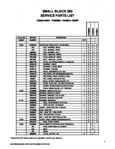
10105123. BLOCK CAST IRON (4 BOLT,1PC RR SEAL). 1. X ... SMALL BLOCK
350. SERVICE ... GM PERFORMANCE PARTS CRATE ENGINE PARTS LIST. 1 ...
are handled only as a sales item, and therefore both types of parts are not
supplied as .... I numeri nella lista del materiale d'imballagio e accessori indicano
il.
THIS MANUAL CONTAINS THE ILLUSTRATED PARTS LIST FOR MODELS:
STT52A-23CH with a serial ... Engine and Attaching Parts (22HP Kawasaki) .
General information. This spare parts list applies to the following: Description.
Part number. Hydraulic breaker RX 2. 8460 0500 38. Use only authorized parts.
Spare parts list. Forward and reversible plate. MV 305, 320. Valid from serial
number. 13003001. MV 305 Honda. 13003001. MV 320 Hatz www.cp.com ...
DESCRIPTION. PART NUMBER. 1.6 GPF. 1.28 GPF. Tank Lever LH. Bolt Cap Kit
. Fluidmaster 400A Inlet. Flushvalve Assembly - 1.6 GPF. Flushvalve Assembly ...
Use of service/replacement parts other than original equipment parts may void
your warranty. ALL UNNUMBERED. ITEMS ARE INTERCHANGEABLE.
DESCRIPTION OF PART NO. REQ. Motor assembly (1) Motor mount plate (1) Screw (2) Gearcase assembly (1) Variable electronics switch assembly (1) Screw (5) Screw (4) Housing Connection Clip (1) Forward/reverse button (1) Service nameplate (1) Warning label (1) Fuel gauge label (1) Fuel gauge (1) Housing assembly (1) Housing halve- left (1) Housing halve- right (1) Metal pin (2)
NOTES: 1,2,4 IMPORTANT: See the back side of this bulletin if servicing the motor assembly (1) or the gearcase assembly (4). 3
Seating torque is to be 6-12 Kgf-cm (5-10.5 in-lbs)
5, 1
Solder red lead wire from electronics module assembly (5) to positive terminal (red) of Motor Assembly. Solder black lead wire from electronics module assembly (5) to negative terminal of Motor Assembly.
5, 13
Insert the fuel gauge (13) wire assembly into the electronics module assembly.
MILWAUKEE ELECTRIC TOOL CORPORATION 13135 W. Lisbon Road, Brookfield, WI 53005 Drwg. 4
Early M12™ Handle Sets utilize Housing Connection Clip No. 42-70-0055. Install this clip design by aligning the side rails of the clip with the two slots in the handle set. Gently push into place with the aid of a small flat blade screwdriver or a similar instrument. Be sure that the clip is properly seated in both slots and that the clip is flush to sub-flush to the end of the handle set. To remove the clip, use the same small flat blade screwdriver or a similar instrument and push the clip out of the handle set. If the clip is loose or will not stay in place, a needle nose pliers can be used to gently bend/pinch the side rails of the clip. If the clip is damaged do not use, replace with a new 42-70-0055 housing clip.
Slots
Recess in early handle sets may only have the slots to accommodate a housing clip. Use 42-70-0055 only in this situation.
42-70-0055
Updated M12™ Handle Sets utilize Housing Connection Clips No. 42-70-0055 and 42-700058. (The 42-70-0058 is a preferred upgrade). Install this clip design by aligning the side rails of the clip with the two slots in the handle set. Gently push into place with the aid of a small flat blade screwdriver or a similar instrument. Be sure that the clip is properly seated in both slots and that the tab of the clip snaps down in the round dimpled cavity of the handle set. Be sure that the clip is flush to sub-flush to the end of the handle set. To remove the clip, use the same small flat blade screwdriver or a similar instrument and lift up on the clip tab while pushing the clip out of the handle set. Use a needle nose pliers to gently rebend the clip tab if necessary. If the tab on the clip is damaged during this process and is loose or will not stay in place, replace with a new 42-70-0058 clip.
Slots
Dimples
Recess in this handle set design has slots and dimples to secure a housing clip. The 42-70-0055 can be used but the 42-70-0058 is preferred in this situation.
42-70-0058
Newer M12™ Handle Sets utilize Housing Connection Clip No. 42-70-0058. Install this clip design by aligning the side rails of the clip with the two slots in the handle set. Gently push into place with the aid of a small flat blade screwdriver or a similar instrument. Be sure that the clip is properly seated in both slots and that the tab of the clip snaps down in the rectangular cavity of the handle set. Be sure that the clip is flush to sub-flush to the end of the handle set. To remove the clip, use the same small flat blade screwdriver or a similar instrument and lift the clip tab out of the cavity while pushing the clip out of the handle set. Use a needle nose pliers to gently rebend the clip tab if necessary. If the tab on the clip is damaged during this process and is loose or will not stay in place, replace with a new 42-70-0058 clip.
Slots Dimple Tab Cavity Recess in newer handle sets have two slots, a dimple and a tab cavity to accommodate the newer housing clip design.
42-70-0058
SUBJECT:
23-30-0095 MOTOR ASSEMBLY with NYLON or ALUMINUM Motor Mount Plate 14-29-0095 GEARCASE ASSEMBLY with NON-MACHINED or MACHINED Gearcase
Motor Mount Plate of service replacement 23-30-0095 MOTOR ASSEMBLY can be either NYLON or ALUMINUM.
When replacing either the 23-30-0095 MOTOR ASSEMBLY or 14-29-0095 GEARCASE ASSEMBLY the mating of the motor assembly with the gearcase is dependent on the original motor mount plate of 2401-20 Hex Driver being serviced. If a 2401-20 Hex Driver original motor has a nylon motor mount then replace any service replacement MOTOR ASSEMBLY aluminum motor mount with the original nylon motor mount plate from the original motor before installing it to the gearcase and vice versa - if the original motor has a aluminum motor mount then replace the service replacement MOTOR ASSEMBLY nylon motor mount with the original aluminum before installing to the gearcase.
NON-MACHINED GEARCASE Nylon Motor Mount Plate must be used
Notch for Nylon Motor Mount Alignment Tab will be utilized
MACHINED GEARCASE Aluminum Motor Mount Plate must be used
Gearcase has machined undercut
NOTE: Highlighted small tab of Motor Mount Plate (either NYLON or ALUMINUM) must-be-in-line with positive (+) terminal side of motor as illustrated to allow for correct placement of the motor and wiring in the handle of the tool A dab of red paint indicates positive (+) terminal