Nov 5, 2003 - Move the cottage to the center */. MVF 1E1A,6A,384E;. /* Say Hello to the ..... The Hardware/Software Interface. Morgan Kaufmann Pub. 1997.
Session F1C A VISUAL INSTRUCTION SET ARCHITECTURE AND SIMULATION TOOL FOR COMPUTER ENGINEERING EDUCATION A. Yavuz Oruç1 and Emre Gunduzhan2 Abstract- This paper presents a holistic approach to develop a visual simulation system for computer engineering education. This approach starts out with a visual instruction set architecture, and plans to build the other layers of computers by moving up and down from such an instruction set architecture specification in a simulation environment. As a step in this direction, an instruction set architecture, called CodeMill, has been developed and used successfully in teaching computer organization courses at the University of Maryland as well as computer science classes in a number of secondary school programs, and is being extended to include compiler and operating systems layers into its simulation environment. The paper describes the CodeMill and its simulation environment, and presents a road map for expanding it into a comprehensive system for learning core computer engineering concepts with hands-on tools. Index Terms: computer engineering, computer programming, processor simulation, visual simulation.
I. INTRODUCTION One of the major challenges of teaching computer engineering courses is to demonstrate how things tie together in various layers of computers to make them work the way they do. The difficulty of teaching computer engineering courses is widely acknowledged [1,2], and a number of recent articles on teaching computer design and architecture suggest that hands-on simulation and learning tools are essential for an effective instruction of the subject material [3,4]. Existing processor simulation tools help explain how various parts of computers function and illustrate the operations of computers at various levels of specificity. Nonetheless, these simulation tools are more suitable for generating statistical information and validating architectural innovations than for classroom instruction. An alternative approach, that is also used in computer engineering courses, is to assign design projects with the desired effect of involving students in the process of architecting a contemporary processor in a simulated environment if not one in silicon. One problem with this 1
Electrical and Computer Engineering Department, University of Maryland, College Park, MD 20740. 2 Nortel Networks, Germantown, MD 20874.
approach is that such design projects are typically written in programming languages that do not readily support graphics
and visualization capabilities. To be sure, Java and other visual programming languages have provided some relief in this regard, but students have to conquer yet another highlevel programming language to study computer engineering. Moreover, the focus needs to remain on learning computer engineering concepts rather than mastering programming languages. Teaching computer engineering concepts effectively involves clear expositions of dynamic processes such as program translation and assembly, instruction fetch, decode, and execution, microsequencing, pipelining, branch prediction, multithreading, memory operations, caching, subroutine calls, stack processing, among others. Widely circulated computer architecture texts often resort to sequences of diagrams, each serving as a snapshot of a sequential or pipelined processor executing a program or carrying out a computation [5,6,7]. While the snapshot approach works for simple examples, it is clearly not very effective to illustrate the execution of programs or dynamics of program flow and control in more realistic settings. More realistic visualizations of the executions of programs in machine layers are often accomplished using microarchitecture simulation tools such as SPIM [8], RSIM[9], Proteus [10], SimOS [11], and VMW [12]. For example, in SPIM, MIPS R2000/3000 assembly language programs can be stepped and/or executed along with a visual description of the data and control registers. Like SPIM, RSIM is an execution-driven processor simulator that derives from MIPS R10000 processor with much more extensive simulation capabilities, including multiprocessor simulations. It provides modeling and simulation of instruction-level parallelism behavior of superscalar architectures including instruction prefetching and pipelining, out-of-order execution, static and dynamic branch prediction, and register renaming, among other features. At the end of a simulation run, RSIM generates a set of statistics including the total execution time, instruction mix profile, busy and stall cycles as well as the usage of various functional units of the processor that is simulated. Proteus is another execution-driven multiprocessor simulator with message-passing and shared-memory capabilities. It can be extended to include network, memory and other functional units in the simulations, and it runs programs written in a variant of the C language. SimOS is a systems level simulation environment that allows the simulation of computers systems in both hardware and software layers including operating system processes. Unlike SPIM, RSIM, and SimOS, VMP is a trace-driven simulator, which relies on the instruction and data traces from an executed program
0-7803-7961-6/03/$17.00 © 2003 IEEE November 5-8, 2003, Boulder, CO 33 rd ASEE/IEEE Frontiers in Education Conference F1C-1
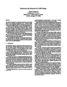
Session F1C to simulate and display processor behavior in executing visually and hierarchically. Given the complexity of a programs. The target machine is specified by the simulator computer as a system, it is only practical to structure this both in machine and micro architecture terms to describe its information in terms of the learning objectives of the user. It instruction set architecture, instruction timing, machine is generally agreed that the operations of a computer are best organization and behavior. The simulator then combines this described by viewing it as a hierarchical system of layers. architectural specification with an execution trace of a These layers are typically identified as shown in Figure 1. program to generate a trace animation and visual In each of these layers, a set of parameters and/or entities performance statistics. can be of interest to the user of a simulator. For example, in While these processor simulators provide powerful the application layer, the user is more likely to be interested simulation capabilities, their main weakness from the point in text, picture, or sound information whereas in the circuit of computer engineering education is that they are not layer, voltages, currents, and power consumption would be designed as instructional tools with the exception of SPIM, more appropriate kinds of information for a user to peruse. but rather for testing and analyzing the performance of new computer architecture ideas and systems. Another critical deficiency is that they are not easy to set up and operate, and Application Layer this makes them unattractive for classroom use. The CodeMill processor architecture and simulation environment Operating System Layer described in this paper is designed to overcome these problems and provide a user friendly and visual processor significance visual Machine Layer simulation environment. This is accomplished by integrating of raw data content machine level simulation and assembly language Microarchitecture Layer programming together under a simple but powerful graphical user interface. Besides the visual animation of register operations, CodeMill includes a set of graphics instructions Logic Layer to facilitate pixel and raster graphics animation as well. Register and pixel animations together with the animations Circuit Layer of stack and memory operations make CodeMill a very powerful simulation system. At the same time, CodeMill is FIGURE 1. A layered view of a computer. an ongoing project and its description in the paper is only intended to serve as an example of a visual processor As indicated in the figure, the visual content of the simulator and to motivate more work on similar and more information increases as we move from the circuit layer comprehensive visual processor simulators. We should note towards the application layer, but at the same time, the that there have been other efforts that emphasize significance of the raw data decreases. This fact must, visualization in processor simu lation. In particular, clearly, be taken into account in the design of the visual Carpinelli et al. focus on the impact of using visualization in interface. processor simulation on learning core digital design and The determination of precisely which set of parameters computer architecture concepts using a simple instruction set or entities should be visualized in each layer is not an exact architecture [13,14,15]. The CodeMill instruction set science, and might depend on the intended use of the architecture described in this paper is much more extensive simulator as well as by the limitations of the available and, besides providing machine layer visualizations, it resources. Nonetheless, there should be a minimal set of includes graphics instructions for realistic animations of parameters without which the visualization would be computer programs. incomplete in each layer. For example, it will be difficult to The rest of the paper is organized as follows. Section II conceptualize how a program is executed at the machine discusses the parameters that are critical in visualizing layer without displaying the contents of what is called a computer operations in various layers. Section III presents program counter or instruction counter. Similarly, the our ideas on instruction set design for processor simulators. contents of the instruction and data registers should be Section IV describes the issues in integrating hardware and included in this minimal set of visualization parameters software concepts together. The paper is concluded with should the user be interested in the outcome of executing a potential extensions and future work in Section V. program. Thus we can state: II. VISUAL S IMULATION IDEAS Remark: A machine layer processor simulator must, at a minimum, simulate the program counter, instruction register, A number of factors must be considered when designing a and a subset of data registers in order for the user to track the visual interface for a processor simulator. One is the level of behavior of the processor that is being simulated. detail at which the simulation information is presented to the user. Another is how this information is represented both 0-7803-7961-6/03/$17.00 © 2003 IEEE November 5-8, 2003, Boulder, CO 33 rd ASEE/IEEE Frontiers in Education Conference F1C-2
Session F1C The register space is surely critical to visualize the operations in the machine layer of computers, but there are other entities of interest such as the pixel space where pictures are created and animated. Likewise, there is the stack space where operands and addresses are pushed and popped during the course of a computation. Finally, there is the program space where machine instructions are compiled together to form programs.
verify that registers cannot hold numbers that are greater than 127 and less than –128. This means that if the user needs to work with integers outside the interval [-128,127], either the register size should be increased by reconfiguring the scratchpad registers or his program must be modified to accommodate operating on numbers outside this range.
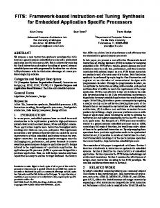
A Working Example: CodeMill Visual Interface
Instruction set design is one of the most critical aspects of developing a processor simulator. Ideally, one can include as many instructions as desirable in the simulator since the instructions are implemented in software. On the other hand, instruction sets are subject to various hardware resource and implementation constraints that must also be taken into account in designing them.
Some of these visual simulation ideas have been implemented in CodeMill [16]. In particular, the CodeMill visual interface, which is shown in Figure 2, has been designed by taking into account all these considerations. The window on the left consists of a pixel space for the animation of a raster screen (upper portion), and a register space (lower portion) where the control and data registers of the simulated processor are displayed. On the right hand side is the program window where the user enters programs. This window also includes a template of all the instructions in CodeMill as well as command console for executing, suspending, resuming or stepping through a program, among several other commands. /* Written By: A. Yavuz Oruc */ /* Paint lower part of the house */ STF 1E3E,24,0F; STF 2040,20,AD; STF 403E,24,0F; STF 4040,20,AD; STF 643E,24,0F; STF 6440,20,96; STF 294F,0C,0F; STF 2A50,0A,94; CPF 294F,0C,494F; STF 6C4F,0B,0F; STF 6C55,0B,0F; STF 6D50,0A,02; STF 6D55,0A,02; STF 6F57,03,0F; /* Paint the roof */ LDI R0,X1E; LDI R3,X2F; LOOP1:MOV R1,R0; LDI R2,X3D; LOOP2:STF R1R2,01,85; DEC R2; STF R1R2,01,85; DEC R2; INC R1; JCD R1,