gers becomes larger, as explained in Sections V and VII, which increases the ...... [10] A. R. Calderbank and N. J. A. Sloane, âNew trellis codes based on.
IEEE TRANSACTIONS ON INFORMATION THEORY, VOL. 57, NO. 8, AUGUST 2011
5203
Signal Codes: Convolutional Lattice Codes Ofir Shalvi, Member, IEEE, Naftali Sommer, Senior Member, IEEE, and Meir Feder, Fellow, IEEE Abstract—The coded modulation scheme proposed in this paper has a simple construction: an integer sequence, representing the information, is convolved with a fixed, continuous-valued, finite impulse response (FIR) filter to generate the codeword—a lattice point. Due to power constraints, the code construction includes a shaping mechanism inspired by precoding techniques such as the Tomlinson-Harashima filter. We naturally term these codes “convolutional lattice codes” or alternatively “signal codes” due to the signal processing interpretation of the code construction. Surprisingly, properly chosen short FIR filters can generate good codes with large minimal distance. Decoding can be done efficiently by sequential decoding or for better performance by bidirectional sequential decoding. Error analysis and simulation results indicate that for the additive white Gaussian noise (AWGN) channel, convolutional lattice codes with computationally reasonable decoders can achieve low error rate close to the channel capacity. Index Terms—Achieving AWGN capacity, coded modulation, convolutional lattice codes, lattice codes, sequential decoding, shaping.
I. INTRODUCTION
S
EVERAL years ago [42] we came up with a simple construction for coded modulation: pass the uncoded information sequence (represented as an integer or an odd integer sequence) through a filter to output a continuous-valued modulated codeword. To overcome the power increase at the output, we proposed to apply a shaping mechanism inspired by precoding techniques such as the Tomlinson-Harashima filter. We termed the scheme “signal codes” due to the signal processing interpretation of the code construction. Following [48], this paper presents and analyzes this scheme in depth. It first observes that by convolving the integer sequence with the impulse response of the filter one gets a “convolutional” lattice. The code described above, which can be naturally termed “convolutional lattice code,” is obtained by taking a finite region of this lattice using a shaping operation. It turns out that even a short length FIR filter, properly designed, can generate a lattice whose Hermite parameter (or nominal coding gain, normalized minimum distance [13]) is large. As demonstrated later in the paper, over the AWGN channel the scheme can work at a rate Manuscript received June 25, 2008; revised January 19, 2011; accepted March 13, 2011. Date of current version July 29, 2011. The work was supported by the Israeli Science Foundation by Grant 634/09. The material in this paper was presented at the IEEE Information Theory Workshop, Paris, France, 2003. O. Shalvi is with the Department of Electrical Engineering–Systems, TelAviv University, Tel-Aviv, Israel, and also with Anobit Technologies, Herzlia, Israel. N. Sommer is with the Department of Electrical Engineering–Systems, TelAviv University, Tel-Aviv, Israel, and also with Anobit Technologies, Herzlia, Israel. M. Feder is with the Department of Electrical Engineering–Systems, Tel-Aviv University, Tel-Aviv, Israel. Communicated by H.-A. Loeliger, Associate Editor for Coding Techniques. Color versions of one or more of the figures in this paper are available online at http://ieeexplore.ieee.org. Digital Object Identifier 10.1109/TIT.2011.2158876
[or signal-to-noise ratio (SNR)] close to the channel capacity with practical decoders. This fact, together with their simple construction, makes convolutional lattice codes a viable, attractive alternative for practical coded modulation. The usage of lattice codes as a natural and elegant alternative to random Gaussian codes [43], [44] in the continuous-valued space is well known. As shown in [15]–[17], [33], [34], [53], lattice codes attain the AWGN channel capacity. Lattice codes are the Euclidean space analog of finite alphabet linear codes. Considering the rich arsenal of finite alphabet (binary) linear codes that includes algebraic codes, convolutional codes, modern capacity achieving turbo codes [9], and low density parity check (LDPC) codes [25], polar codes [4], and so on, one may have expected that an analog situation will exist for lattice codes. Unfortunately, this is not the case. There are some specific lattice codes based on known low dimensional classical lattices [13]. Other constructions utilized finite alphabet algebraic (or other) codes [10], [21], to “thin out” the integer lattice by the code constraints. Yet until recently, the analogy was not utilized for designing lattice codes directly in the Euclidean space or in finding specific capacity achieving lattice codes. Convolutional lattice codes, presented here, provides the desired analogy to finite alphabet convolutional codes. The uncoded symbols are convolved with a “filter pattern” to generate a codeword. Since the codes are used over the Euclidean space (real or complex), the operations are done in the real or complex field. Noticing that the filter output has an increased power which in effect, cancels out the coding gain, the code construction includes a mechanism inspired by pre-coding techniques such as the Tomlinson-Harashima filter. This “shaping” can either guarantee that the resulting lattice point will reside in the cube corresponding to the input integer sequence (or the input PAM/QAM constellation), or even better, reside in a more power efficient shaping domain. In the latter case, the code will also have a shaping gain in addition to the lattice coding gain. Notice that this technique actually provides a general framework for constructing lattice codes directly in the Euclidean space, composed of linear (or filtering) operation and shaping operation. This construction may be an alternative to the well known techniques (constructions A-D, [13]) that generate lattices from finite alphabet linear codes. The role of the nonlinear shaping (pre-coding) operation should be further motivated. Shaping “whitens” the codewords. Otherwise one would expect that the codeword spectrum will be proportional to the colored filter frequency response. Good codes, and in particular capacity achieving codes, should have a white spectrum! It also clarifies the major distinction between convolutional lattice codes and other coding schemes that use linear filtering, such as Partial Response Signaling (PRS) and Faster Than Nyquist (FTN) signaling [40]. These techniques also filter the input integer sequence, but do not employ shaping, as one of their goals is to color the output to a desired
0018-9448/$26.00 © 2011 IEEE
5204
IEEE TRANSACTIONS ON INFORMATION THEORY, VOL. 57, NO. 8, AUGUST 2011
may well be the best solution in terms of performance for continuous-valued channels. Convolutional lattice codes, presented here, complement the picture for cases where low delay is desired, or in cases where a somewhat lower rate can be tolerated in turn for low computational complexity, obtained by the sequential decoding. The outline of this paper is as follows. An introduction to lattices and lattice codes is presented in Section II, followed by a definition of convolutional lattice codes (Section III) and methods to design lattices for convolutional lattice codes (Section IV). Then, Section V presents several shaping algorithms that can be used for practical lattice coding for the AWGN channel, and Section VI discusses bounds on the error probability. In Section VII, a description of computationally efficient decoders is provided, followed by simulation results in Section VIII. II. LATTICES AND LATTICE CODES Fig. 1. An example of the shaping operation for a 2-D lattice.
spectrum. The distinction and the advantages of convolutional lattice codes over these techniques is further discussed later. Convolutional lattice codes can be decoded efficiently by sequential decoding [56]. Unfortunately, Viterbi decoding [54] or backward-forward BCJR [8] decoding cannot be used. This is since the shaping operation increases substantially the range of possible integer values for any filter tap, and hence the number of states in the Viterbi decoder. Sequential decoding may require high computational efforts to exceed the cut-off rate, yet it can guarantee low average delay, and can handle convolutional lattice codes with long filter patterns. For better performance, we also propose a more elaborate bidirectional [29] sequential decoding, and allow larger memory for the decoding algorithm. Several algorithmic techniques are provided that further reduce the computational complexity. Error analysis and simulation results for the proposed algorithms indicate that convolutional lattice codes with computationally reasonable decoders dB from the AWGN channel can achieve low error rate at capacity. Since some of the loss is due to practical implementation compromises, the results actually indicate that the lattice itself can attain a low error probability at less than 1 dB off the optimum. Note that the proposed scheme is attractive for intersymbolinterference (ISI) channels. The code filter and the ISI filter are essentially combined, resulting in a seamless unification of equalization and decoding. The general concept of designing codes directly in the Euclidean space, originated with convolutional lattice codes, was extended a few years later with the introduction of “low density lattice codes” (LDLC) [47], the lattice analog of LDPC codes. In LDLC the lattice generator matrix has a sparse inverse. It was shown that by proper choice of the elements of this sparse inverse, LDLC can approach the AWGN channel capacity with iterative decoding of linear complexity in the block length. More recently LDLC’s become practical with shaping [49], and highly efficient decoding [30], [57]. Thus, LDLC’s
( ) is defined as the A real lattice of dimension in set of all linear combinations of real basis vectors, where the coefficients of the linear combination are integers
is the generator matrix of the lattice, whose columns are the basis vectors which are assumed to be linearly independent . over The Voronoi region (or Voronoi cell) of a lattice point is the set of all vectors in for which this point is the closest lattice point, namely
where
. The volume of the Voronoi cell of a lattice is , or in case is square. The minimum squared distance of a lattice is defined as the minimal squared Euclidean distance between any pair of lattice points. Clearly, the minimum squared distance of a lattice equals the squared length of the shortest nonzero lattice point (1)
is defined as the The kissing number of a lattice number of nearest neighbors to any lattice point. The Hermite parameter of an -dimensional lattice, also referred to as the nominal coding gain of the lattice, is defined as [24]. This definition of the nominal coding gain properly normalizes the minimum squared distance by the density of the lattice points such that it becomes invariant to scaling. A lattice code of dimension is defined by a (possibly and a shaping region (e.g., an shifted) lattice in -dimensional sphere), where the codewords are all the lattice points that lie within the shaping region . Straightforward encoding of an integer information vector by the lattice point will not guarantee, in general, that only lattice points within the shaping region are used. Therefore, the encoding operation must be accompanied by shaping, where
SHALVI et al.: SIGNAL CODES: CONVOLUTIONAL LATTICE CODES
5205
Fig. 2. A typical lattice coding scheme for the discrete-time AWGN channel.
instead of mapping the information vector to the lattice point , it should be mapped to some other lattice point , such that the lattice points that are used as codewords belong to the shaping region. The shaping operation is the mapping of the integer vector to the integer vector . The shaping operation is illustrated in Fig. 1 for a two-dimensional lattice whose generator matrix is
Each information integer is assumed to be in the range to , so a two-dimensional lattice code needs to use lattice points as codewords. If no shaping is used, the information vector is mapped directly to and the codewords will be the 81 lattice points inside the parallelogram. If a rectangular or spherical shaping region is used, each information vector should be mapped to one of the 81 lattice points inside the shown rectangle or circle, respectively, resulting in average power which is lower by 4.59 and 4.77 dB, respectively, than the no-shaping case. Note that traditionally the term “shaping gain” is defined with respect to the average energy associated with the hypercube shaping domain, and is bounded by 1.53 dB [24, Sect. IV.A]. However, the shaping operation, as defined above, can reduce the average energy by much more than 1.53 dB, since the starting point (after straightforward mapping of the integer vector to the lattice point ) may have average energy which is much higher than the average energy of a hypercube, as illustrated above for the example of Fig. 1. A typical lattice coding scheme for the discrete-time AWGN channel is summarized in Fig. 2. First, the shaping operation maps the information integer sequence to another integer sequence , as described earlier. The new sequence is encoded by multiplication with the lattice generator matrix. Then, the resulting lattice point is transmitted through the AWGN channel, which adds additive Gaussian noise with variance . , where is the avThe SNR is defined as erage energy of a single component of the transmitted lattice point . The effective coding gain of a lattice code is measured by the reduction in required SNR to achieve a certain target error probability relative to using the cubic lattice , with a hypercube shaping region, using the same data rate.
At the receiver, a maximum-likelihood (ML) decoder should find the closest lattice point within the shaping region to the noisy observation in the Euclidean space. For a general lattice, the computational complexity of finding the closest lattice point to a given vector is exponential with the lattice dimension [1]. Therefore, lattices for practical use should have some structure that enables simple decoding. Finally, an inverse shaping operation is performed to the detected lattice point in order to recover the information integers. is defined as the set An dimensional complex lattice in of all linear combinations of a given basis of linearly indepenwith complex integer coefficients. All the dent vectors in properties of real lattices and real lattice codes that were cited above can be extended in a straightforward manner to complex lattices and complex lattice codes. III. DEFINITION OF CONVOLUTIONAL LATTICE CODES Convolutional lattice codes are defined as lattice codes which genare based on an -dimensional lattice whose erator matrix has the following Toeplitz form
.. . .. . .. . .. . .. .
.. . .. .
.. . .. . .. . .. . .. . .. . .. . .. .
.. . .. .
.. . .. . .. . (2)
.. . .. .
are the impulse response coefficients of where a monic causal FIR filter, which will be denoted as the generating filter. As will be explained in Section V, it is worthwhile to choose a minimum-phase filter (i.e., a filter whose zeros are inside the unit circle) due to the proposed shaping methods. The -transform of the generating filter will be denoted by .
5206
IEEE TRANSACTIONS ON INFORMATION THEORY, VOL. 57, NO. 8, AUGUST 2011
The components of a lattice point , where is an -dimensional vector of integers, are the convolution of the sequence of components of with the generating filter (3) for , where is assumed zero outside the range 1 to . For convenience, we shall assume at this point are real valued and is a real lattice, but the that observations below can be extended in a straightforward manner to complex lattices. We shall now show that this lattice has better (or at least than equal) nominal coding gain , which can be regarded as a latthe uncoded cubic lattice tice whose generator matrix is the identity matrix. First, we shall show that both lattices have the same density, i.e., same . For the cubic lattice , for value of every , where as discussed in Section II, for the proposed lat. As shown in Appendix A, for tice we have (This should not be surprising, since the first rows of form a lower diagonal matrix whose determinant is exactly 1). Therefore, for large , is nearly a volume preserving transformation, and the density of the proposed lattice approaches the density of the cubic lattice. is greater of equal for the It is left to show that proposed lattice than for the cubic lattice. For the cubic lat. For the proposed lattice, tice, we clearly have . denote the shortest nonzero lattice point by be the smallest index for which , where Let denotes the component of . As noted above, is the convolution of the sethe sequence of components of with the generating filter. Since quence of components of , the generating filter is monic and causal, and thus
response signaling (PRS) and faster than Nyquist (FTN) signaling (see [40] for an overview of these techniques). Both these techniques obtain bandwidth efficiency by introducing intentional ISI to a sequence of integer information symbols. Therefore, these schemes essentially use lattice points, where the lattice generator matrix is of the form (2). However, the basic difference is that these schemes do not employ shaping. As indicated earlier, without shaping, the coding gain of the lattice can not be utilized, since the improvement in the squared minimum distance of the lattice versus the cubic lattice is always smaller than the increase in signal power due to the filtering operation. As a result, these schemes try to achieve effective gains in other ways: in PRS, the ISI is designed to narrow the power spectrum of the transmitted signal with minimal degradation to error probability. As already noted in [41]: “Herein lies an important fact about PRS-coded modulation: Free distance cannot be gained via linear convolutions in the complex field; the game is to lose as little as possible, while reducing the bandwidth.” In FTN, the gain is higher data rate, which is achieved by using signaling rate which is higher than the Nyquist rate of the channel, and handling the unavoidable ISI at the receiver. Convolutional lattice codes inherently differ from these two techniques, since employing the shaping operation enables to utilize the lattice coding gain, rather than changing signaling rate or signal bandwidth. Therefore, it is applicable to the simple AWGN channel, where PRS and FTN envision a different channel scenario, namely one where signals must have a certain power spectral density (PSD) shape or property. IV. LATTICE DESIGN: CHOOSING THE FILTER In order to design a convolutional lattice code, we need to choose the generating filter. We shall seek generating filters that . As will be shown later, it is beneficial to use yield high complex-valued lattices that are based on a complex-valued generating filter. For simplicity, we shall examine complex-valued , i.e., their generating filters that have a th-order zero at -transform is
(4)
(5)
Note that it is essential to use the shaping operation, as described in Section II, in order to benefit from the improved nominal coding gain of the lattice. Otherwise, assuming that the information integers are independent, identically distributed (i.i.d.), the lattice points are filtered sequences of i.i.d. integers, than the whose power is larger by a factor of power of the i.i.d. integers. However, by considering the lattice point that corresponds to an “impulse” integer vector (with ’1’ in the first element and zero otherwise), it can be seen that the improvement in the squared minimal distance due to filtering is , so it is never upper bounded by the same term enough to justify the power increase, unless shaping is used. Several shaping methods for convolutional lattice codes will be described in Section V. In fact, incorporating the shaping operation is one of the basic differences between convolutional lattice codes and other coding schemes that employ linear filtering, such as partial
where due to the minimum-phase restriction. This simple choice is not necessarily optimal, but the experimental results in the sequel indicate that it can lead to lattices with good coding gains. (i.e., ) it can be easily seen For . Since , the nominal coding that , it is more difficult to gain is bounded by 2 (3 dB). For analytically and a numerical search is required. find Methods that were developed for finding the minimum distance between output sequences of ISI channels can be applied here, and we have chosen to use the approach of [6], properly modified to our case. The resulting search algorithm, whose details are presented in Appendix B, finds all the lattice points within a given hypersphere, by developing a tree of all possible integer sequences, and truncating tree branches as soon as it can identify that all the corresponding lattice points will lie outside the hypersphere. The tree is searched in a depth first search (DFS)
SHALVI et al.: SIGNAL CODES: CONVOLUTIONAL LATTICE CODES
Fig. 3. The squared minimum distance as a function of the filter’s zero for different value of the zero’s magnitude.
Fig. 4. The squared minimum distance as a function of the filter’s zero for different value of the zero’s magnitude.
5207
P
= 2. d
is shown as a function of the zero’s phase, where every plot is for a
P
= 3. d
is shown as a function of the zero’s phase, where every plot is for a
manner, which can be easily implemented using recursion techniques. In fact, this search algorithm is equivalent to a sphere decoder [1], with the proper modifications due to the shift invariance of the convolution operation and the band Toeplitz structure of the generator matrix .
Using this algorithm, the squared minimum distance was . Figs. 3 and 4 show found for various values of and , respectively. The squared the results for minimum distance is shown as a function of the phase , with a different plot for each value of the magnitude .
5208
IEEE TRANSACTIONS ON INFORMATION THEORY, VOL. 57, NO. 8, AUGUST 2011
TABLE I HIGH CODING GAIN FILTER PATTERNS
The figures are for for relation
radians, where the values can be obtained using the symmetry and the periodicity relation , where denotes the minimum . These squared distance as a function of for a fixed relations are derived in Appendix C. It can be seen that the squared minimum distance improves as the spectral null of the filter becomes deeper, either by inor by letting the zero apcreasing the number of zeros proach the unit circle more closely. However, as the spectral notch becomes deeper, the dynamic range of the shaped integers becomes larger, as explained in Sections V and VII, which increases the decoding and shaping implementation complexity. , a global The phase has a significant effect, and for a given . optimum value for exists that maximizes Several generating filters with high are summarized in Table I. For each generating filter, the table shows the squared minimal distance and the nominal coding gain of the resulting lattice (assuming the lattice dimension is large enough, as explained in Section III). The table also shows the nonzero portion of the integer vector for which is the shortest nonzero lattice point (where throughout this paper the term “nonzero portion” of a vector means the portion that starts with the first nonzero component and ends with the last nonzero component). Note that all the integer sequences in the third column of Table I maintain an interesting symmetry. Denote the , the length of the integer sequence by . Then, for ’th element and the ’th elements are equal up to comor plex conjugation followed by multiplication by (where the same factor is used for the whole sequence). It can be seen that even short filters with , , and zeros can achieve considerable nominal coding gains of more than 6, 8, and 9.5 dB, respectively, where the shortest lattice points correspond to reasonably short integer sequences. Consider the special case of . In this case, the generating , it approaches one of the filter is real-valued, and for or . well-known partial response channels As can be seen from Figs. 3 and 4, these filters have considerable (though not optimal) coding gain. However, as shown in [2], these filters have null error sequences, i.e., infinite-length integer sequences that yield a sequence of zeros when filtered with these filters. This singularity is not desirable, since the norm of many lattice points will be close to , making the effective coding gain much smaller than the nominal coding gain. Also,
buffers of sequential decoders will overflow with high probability due to many possible candidates with short distance from the observation. In fact, when Fig. 4 was generated, the search algorithm could not find the minimum distance for the case of and with reasonable computational complexity is not shown due to this reason, and as a result the value of for this combination. As a result, from now on we shall assume a complex , resulting in a complex lattice. Note that in case a real lattice is required (e.g., in a baseband communication system), a complex lattice can be transformed to a real lattice by using the real and imaginary parts of each lattice point component as two independent real components. demonstrates that nominal coding The behavior for gain does not necessarily guarantee effective coding gain. In fact, the nominal coding gains of dense -dimensional lattices while the effective coding gain is become infinite as bounded by channel capacity [24]. Therefore, the generating filters will be further checked for their effective coding gain using bounds on error probability (Section VI) and numerical simulations (Section VIII). V. SHAPING As discussed in Section III and throughout, shaping is essential for convolutional lattice codes, otherwise the power increase due to the filtering operation is higher than the increase in minimal distance. As shown in Figs. 1 and 2, the shaping operation should map the information integer vector to another integer is inside a vector such that the resulting lattice point desired shaping domain, such as a hypercube or a hypersphere. We shall assume that the components of the information vector belong to either PAM or QAM constellations, which are defined as follows. An -PAM constellation is defined as the set . An -QAM constellation is defined as the set of complex integers whose real and imaginary parts belong to an -PAM constellation. Assuming equi-probable usage of the constellation values, the average energy of -PAM and -QAM constellations is and , respectively. PAM and QAM constellations use odd-valued integers in order to have a zero-mean constellation with an even number of points. Therefore, it will be more convenient to restrict also the components of the shaped integer vector to odd values. Using only odd values (instead of all integer values) is equivalent to scaling and shifting the lattice. The shaping operation has a close resemblance to the precoding operation for ISI channels, as illustrated in Fig. 5. The purpose of precoding is pre-equalizing the distortion of a linear , which is known at the transmitter, in order to channel avoid the need for equalization at the receiver. In principle, the transmitter can simply filter the data symbols with the inverse , but the inverse filtering operation can sigchannel filter nificantly increase the signal’s power and peak value. The solution is a precoder that maps the sequence of information symbols to another sequence such that the constraints at the channel . input are fulfilled after filtering the new sequence with This is exactly the required operation of the shaping algorithm
SHALVI et al.: SIGNAL CODES: CONVOLUTIONAL LATTICE CODES
5209
Fig. 5. Resemblance between shaping for lattice codes and precoding for ISI channels. (a) Preequalization for ISI channels. (b) A lattice code with shaping for the AWGN channel.
for convolutional lattice codes, where the generating filter replaces the channel inverse . Three shaping methods for convolutional lattice codes will now be proposed, where the first two are indeed based on well-known precoding schemes for ISI channels. A. Tomlinson-Harashima Shaping The first shaping method that we shall consider is based on Tomlinson-Harashima precoding [52], and uses a hypercube shaping domain. The components of the information vector are assumed to be i.i.d. -QAM symbols. The shaping operation is (6) , where and are the th component of the for shaped integer vector and the information vector , respectively, and is a complex integer. The inverse shaping operation (i.e., recovering the information integers from the shaped integers ) is then a simple modulo operation. The integers are chosen such that the real and imaginary parts of the comare in . Substituting (6) in the basic ponents of encoding operation of convolutional lattice codes, we get
form a recursive loop, which will be stable (i.e., does not increase without bound as increases) if and only if the generis minimum phase. It is well known [22] that ating filter except for some special cases (including for example the case ), the output of a Tomlinson-Harashima precoder is of a spectrally white sequence uniformly distributed over , . Since the for both real and imaginary parts, so its power is , the power of power of uncoded -QAM symbols is is almost the same as the uncoded signal power, albeit higher by a factor of , which is negligible for large . The power spectral density of the shaped integer sequence is proportional to , where is the Fourier transform of the generating filter. Thus, is the generating filter has a deep spectral notch (such as the filters in Table I), will be a narrow-band signal. This shaping scheme guarantees the range of the first components of the lattice point, since the filtering and shaping op. The last erations (7) and (8) are done only for components , which correspond to the “convolution tail”, can not be precisely controlled and may therefore have large magnitude. This problem is common to all the shaping methods that are proposed in this section. Three possible solutions are suggested in Appendix D which solve the problem at the price of negligible data rate degradation.
(7) B. Systematic Shaping Therefore, we should choose (8) where denotes the complex integer closest to . Equations (6)–(8) are equivalent to a Tomlinson-Harashima . These equations precoder for the ISI channel
The second shaping scheme is based on flexible precoding [31]. A lattice code that uses this shaping scheme can be regarded as “systematic,” by extending the definition of a systematic binary code, for which the information bits are part of the codeword components, in the following manner. A lattice code will be regarded as systematic if the information integers can be extracted from the corresponding noiseless lattice point by rounding the lattice point components (or part of them, in case
5210
IEEE TRANSACTIONS ON INFORMATION THEORY, VOL. 57, NO. 8, AUGUST 2011
of a nonsquare generator matrix). Since we use odd integers, the rounding operation will be replaced by quantizing to the closest odd integer. For the systematic shaping scheme, the shaping operation is (9) , where the complex integer sequence is for now chosen such that the real and imaginary parts of , the difference between the coded and uncoded sequences, will . By substituting (9) in the basic belong to the interval encoding operation , the required value of is (10) Equations (9)–(10) are equivalent to flexible precoding [31] for . As for Tomlinson-Harashima the ISI channel should be minimum-phase in order to guarprecoding, antee the stability of the recursive loop. With systematic shaping, the lattice point components equal the information integers plus an additive “dither” signal, whose real and imaginary parts have magnitude less than 1. Therefore, it is indeed a systematic lattice code, as defined above. The inverse shaping operation filters to get , and then quantizes the components to get . Alternatively, can be recovered from using (10) and then can be recovered using (9). Following the same arguments that were used for TomlinsonHarashima shaping, the additive dither would generally be uniformly distributed and uncorrelated with the input sequence. Therefore, if the input to the shaping operation is -QAM symbols, the resulting shaping domain is a hypercube, where the real and imaginary parts of the lattice codewords are uniformly dis, and the same power increase tributed in factor of Tomlinson-Harashima shaping exists also here. However, systematic shaping can be combined with standard constellation shaping algorithms, such as trellis shaping [23] or shell mapping [32], such that additional shaping gain of up to 1.53 dB can be potentially obtained. This can be done by applying a constellation shaping algorithm to the uncoded sequence prior to systematic shaping. The combined operation of systematic does not alter the shaping propshaping and filtering with erties of the input signal significantly, since it is equivalent to adding a small dither, so the constellation shaping gain will be retained. C. Nested Lattice Shaping The nested lattice shaping scheme tries to achieve some of the potential 1.53 dB shaping gain benefit of a hypersphere shaping domain over a hypercube shaping domain. Consider the Tomlinson-Harashima shaping operation (6). Suppose that instead of setting in a memoryless manner as in (8), we choose a sethat minimizes the energy of the resulting lattice quence point components , where . Using vector notations for (6), we have (11)
. From (11), we Denote the nonshaped lattice point by . Choosing that minimizes then have is essentially finding the nearest lattice point of the scaled to the nonshaped lattice point , where the chosen lattice codeword is the difference vector between the nonshaped lat. As a result, tice point and the nearest lattice point the chosen lattice points will be uniformly distributed along the . Therefore, the resulting Voronoi cell of the coarse lattice shaping scheme is equivalent to nested lattice coding [12], [17], where the shaping domain of a lattice code is chosen as the Voronoi region of a different, “coarse” lattice, usually chosen as a scaled version of the coding lattice. Such a shaping domain has the potential to attain some of the shaping gain which is attainable by a spherical shaping domain. The complexity of finding the nearest lattice point is the same as the complexity of ML decoding in the presence of AWGN. However, unlike decoding, for shaping applications it is not critical to find the exact nearest lattice point, as the result of finding an approximate point will only be a slight penalty in signal power. Therefore, approximate algorithms may be considered. As shown in Section VIII, close-to-optimal shaping gains can be attained by nested lattice shaping using simple sub-optimal sequential decoders such as the -algorithm (see [7] and references therein). Interestingly, it should be noted that the criterion for good shaping can be generalized to meet the needs of communications systems. For instance, the algorithm can combine power optimization with peak magnitude optimization or with short-time power optimization, or even with spectral shaping optimization that can reduce the bandwidth of the signal, similarly to PRS. D. Shaping for Nonminimum-Phase or Non-FIR Filters The proposed shaping methods incorporate nonlinear feedback loops, which are stable only if the generating filter is minimum-phase. In Appendix E, the shaping algorithms are extended to nonminimum-phase filters, and also to autoregressive, moving average (ARMA) filters, which can have both poles and zeros in the plane. Nonminimum-phase filters may have benefits for fast fading channels or for channels with impulse noise. ARMA filters are useful, for example, when the encoding operation should be combined with preequalization for an ISI channel. Joint preequalization and encoding is also described in this appendix. VI. BOUNDS ON THE PROBABILITY OF ERROR We shall consider complex lattice codes, used for the com(i.e., the plex AWGN channel with complex noise variance ). variance of the real and the imaginary parts of the noise is As explained in Section II, a ML decoder should find the closest lattice point to the noisy observation within the shaping domain. We shall assume that the decoder ignores the shaping domain boundaries, and thus performs “lattice decoding” instead of ML will be defined decoding [17]. The probability of error as the probability that a transmitted lattice point was mistakenly detected as a different lattice point. Due to the linearity of the lattice, the probability of error for such a decoder does not depend on the transmitted lattice point, so we can calculate it under the assumption that the zero lattice point was transmitted. Then,
SHALVI et al.: SIGNAL CODES: CONVOLUTIONAL LATTICE CODES
5211
is bounded by the union bound ([24], properly modified for the complex case) (12) where is the Gaussian error function. The lower and upper bounds of (12) are usually not practical since the lower bound may be too loose, where the upper bound requires an infinite can then be approximated by the union bound estisum. mate, defined as (13) is the kissing number of the lattice, i.e., the where number of nearest neighbors to any lattice point. The union bound estimate is expected to be a good approximation at high signal to noise ratios. Define the effective length of an integer vector as the length of the nonzero portion of . Due to the shift invariance of the convolution operation, for each lattice point that corresponds to an integer vector with effective length , there will be different lattice points with the same norm, corresponding to all possible shifts of the nonzero portion of the corresponding integer vector, where is the lattice dimension. Also, for each lattice point there will be 4 lattice points with the same norm that correspond to multiplications of and . Therefore, we the corresponding integer vector by , where deshall assume that notes the effective length of the integer vector that corresponds to the shortest nonzero lattice point. This assumption holds for all the filters of Table I. In case there are several lattice points with the shortest norm, except for shifts and multiplications by and , the search algorithm of Appendix B will find them, should be furand in such a case the above value of ther multiplied by the number of such points. Regarding the upper bound of (12), it is not necessary to sum over all nonzero lattice points, but only over Voronoi relevant is defined lattice points. A Voronoi relevant lattice point as a lattice point that defines a facet of the Voronoi region of the , where this facet is perpendicular to and interorigin sects it in its midpoint . The set of Voronoi-relevant vectors for which can be defined [1] as the minimal set
Practically, it is hard to find all the Voronoi relevant points of a high-dimensional lattice (A lattice of dimension can have up Voronoi relevant vectors [1]). Therefore, can to be approximated by truncating the infinite sum and taking into account only lattice points whose squared norm is bounded by . We then get the following approximation: (14) In order to use this approximation, the search algorithm of Appendix B can be used to generate a list of all lattice . This list is points whose squared norm is less than then used as an input to a sorting algorithm, whose details are
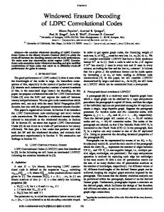
Fig. 6. A histogram of the squared norm of the lattice points for the lattice that corresponds to the third row of Table I.
described in Appendix F, which can determine for each lattice point whether it is Voronoi-relevant or not. As explained in Appendix B, the search algorithm finds a single representative from each group of lattice points that correspond to an integer vector with a shifted nonzero portion, and up to multiplication or . Denote the effective length (as defined above) by of this integer vector by . As noted in Appendix F, if one lattice points within such a group is of the Voronoi-relevant, then all the lattice points in the group are also Voronoi-relevant. Therefore, it is enough to sum in (14) over a single representative from each such group (which is the natural output of the search algorithm) and add a weighting to each element in the sum. coefficient of The search algorithm of Appendix B was applied to the lattice (10.2 generated by the third filter of Table I, with of the cubic lattice). This has required the examdB above ination of 500 billion tree nodes. Fig. 6 shows a histogram of the squared Euclidean distance of the 5593 lattice points that were found, where each bar corresponds to an interval of length 0.25 and shows how many lattice points had squared norm within this interval. The norms assume that all integer values are allowed for the integer vector components, without the restriction of odd integers that was imposed in Section V. When this restriction is applied, the norms should be scaled up by a factor of 4. As explained above, only a single representative is counted from each group of lattice points that corresponds to shifts and multiplicaor . tions by The leftmost bar corresponds to the (single) shortest nonzero lattice point, whose squared norm is 5.90. It can be seen that the first several shortest lattice points (whose squared norms are in the range 5.75–7.25) are discrete points, and there is no “flood” of lattice points whose norm is very close to the norm of the shortest nonzero lattice point. For higher norms, the number of lattice points grows exponentially with the Euclidean norm. The sorting algorithm of Appendix F was then applied to the output of the search algorithm in order to find which of the lattice points is Voronoi-relevant. Almost all the lattice points were
5212
IEEE TRANSACTIONS ON INFORMATION THEORY, VOL. 57, NO. 8, AUGUST 2011
found to be Voronoi-relevant, and only 49 out of the 5,593 lattice points were found to be non-Voronoi-relevant. Most of those 49 points have a relatively high norm (larger than 8.75). The fact that most of the lattice points within the feasible search radius are Voronoi-relevant shows that our search did not go far from the Voronoi region of the origin. These lattice points will be used in Section VIII to compare the simulation results with the bounds of (13) and (14). Note that union bounds are not expected to be valuable, in general, beyond the channel cutoff rate [24]. Note that convolutional lattice codes are similar in their nature to binary convolutional codes in the sense that the probability of an error event starting at symbol does not depend on (ignoring frame boundary effects), where an error event at symbol is defined as a sequence of decoder symbol errors starting at the th symbol. As in (12), this error event probaand upper bounded bility can be lower bounded by where denotes the first element of by the vector . Therefore, the probability of a frame error for a fixed generating filter approaches 1 as the frame length approaches infinity. As shown in Section VIII, for practical frame lengths of several thousands of symbols the frame error rate is still low. As attempting to approach the channel capacity bound requires very large frame length, the length of the generating filter should be increased as frame length increases (see [45]). VII. COMPUTATIONALLY EFFICIENT DECODERS As shown in Fig. 2, the decoder consists of two blocks. First, is detected and then an inverse shaping operation is used to calculate the corresponding . The inverse shaping operation, which is relatively simple, was defined in Section V, and in this section we propose algorithms for detecting . A. Reduced Complexity ML Decoding Consider the discrete-time AWGN channel , where is the component of the transmitted lattice point, is a sequence of zero-mean, i.i.d. complex Gaussian random and is the noisy observation (see variables with variance Fig. 2). As explained in Section II, when a lattice code is used for transmission through the AWGN channel, a ML decoder should find the closest lattice point within the shaping region to the noisy observation in the Euclidean space. Sometimes it is not simple to take the nonlinear shaping operation into account in the decoding process, and then “lattice decoding” [17] can be used, where the decoder ignores the shaping domain (lattice decoding was assumed in Section VI when bounds on error probability were derived). With proper coding and decoding schemes, channel capacity can still be approached although lattice decoding is used [17]. For lattice decoding, the decoder should find the values of the ’s that maximize (15) where , is the generating filter. Finding the values of the ’s is essentially an equalization problem: an integer symbol sequence was convolved with a filter, and has to be detected from the noisy convolution output.
As shown in [20], minimum Euclidean distance decoding can be implemented by a Viterbi Algorithm (VA) whose state is . The number of trellis branches of this VA is equal to the constellation size of , raised to the power of . Therefore, the VA is practical only if is small, and if the dynamic range of the shaped symbols is not prohibitively high. However, good codes can result in values with large range. For example, for Tomlinson-Harashima shaping (Section V-A), the sequence can be obtained by applying the filter on the transmitted sequence , which is a white sequence. As has good generating filters have deep spectral nulls, high spectral peaks and thus it significantly enhances the magnitude of . We note that since the real and imaginary parts of are in the range , the magnitude of can be bounded . In general, a straightforward VA may by be too complex, and a reduced-complexity VA decoder should be used. Reduced complexity Viterbi decoding can follow the wellknown techniques used in the context of convolutional codes and ML channel equalization. One class of such techniques is sequential decoding, e.g., the Fano [26] and stack [55] algorithms. Another class includes list algorithms such as the M-algorithm (see [7] and references therein) and the T-algorithm [3]. A third class is reduced states sequence detection (RSSD) algorithms (e.g., [19]). The computational complexity of sequential decoding of any tree code obeys a Pareto distribution [28]. Such a distribution results in the computational cutoff effect, where for a given information rate, complexity increases abruptly below some cutoff SNR. Therefore, all the above reduced-complexity decoders are expected to be effective only above the cutoff SNR, which is known to be approximately 1.7 dB above the Shannon capacity for the high SNR regime of the AWGN channel [24]. On the other hand, even when the mean or the variance of the number of computations becomes asymptotically infinite, the probability that this number will exceed a predefined threshold is still finite. Therefore, if a target finite error rate is defined, sequential decoders can achieve this error rate with finite (though probably large) complexity even beyond the cutoff rate. In Section VIII we shall show that the sequential stack decoder can be used for decoding of convolutional lattice codes close to the cutoff rate. We shall also use bidirectional sequential decoders with large complexity to demonstrate that low error rate can be achieved even more than 0.5 dB beyond the cutoff rate, with large (but still finite) computational resources. These decoding algorithms will now be further elaborated. B. The Heap-Based Stack Decoder The stack decoder [55] is an algorithm to decode tree codes, which works as follows. A stack of previously explored paths in the tree is initialized with the root of the tree code. At each step, the path with best score in the stack is extended to all its successors, and then deleted from the stack. The successors then enter the stack. For a finite block with known termination state, the algorithm terminates when a path in the stack reaches the termination state at the end of the block. For convolutional lattice codes, each path in the tree corresponds to a sequence of integers , and its successors are sequences of the
SHALVI et al.: SIGNAL CODES: CONVOLUTIONAL LATTICE CODES
5213
form for various values of . Any implementation of the stack decoder should use a properly chosen database that enables efficient implementation of the basic step of the decoder, such as a balanced binary tree [36]. We propose an implementation which is based on the heap data structure [14]. The detailed implementation is described in Appendix G. For the Tomlinson-Harashima and systematic shaping methods, the lattice point components are bounded in the . Therefore, the stack decoder can ignore interval paths for which a resulting lattice point component is outside this range. The resulting decoder is a reduced-complexity approximation of an ML decoder, since it takes into account the shaping domain boundaries. This technique is very effective for complexity reduction, and will be referred to as “x-range testing.” On the other hand, for nested lattice shaping, truncation of incorrect paths is more challenging, so the shaping gain of the encoder is traded with the decoder’s complexity. Each path in the stack is assigned a score that should reflect the likelihood of this path to be the correct path, given the noisy channel observation. Naturally, we would assign scores to the paths in the stack according to the negated squared Euclidean distance of the resulting lattice point from the noisy channel observation as in (15). However, the stack contains paths of different lengths. If we use the negated squared distance, shorter paths will get higher score, as less negative terms are accumulated. This is not desired, since we want to extend the path which coincides with the correct path, even if it is much longer than other incorrect paths in the stack. Therefore, the path scores should be defined such that the effect of path length is eliminated. This problem is addressed in Section VII-C. C. The Fano Metric For sequential decoding of binary convolutional codes, Fano suggested to subtract a bias term from each increment of the natural likelihood score, where the bias equals the code rate . Massey [35] has shown that the score assignment problem is equivalent to decoding of a code with variable length codewords, and that the Fano metric is indeed the correct choice for stack and Fano decoding of binary convolutional codes, in the sense that the most likely path is extended in each step. Massey’s derivation can be extended to the Euclidean case, as done in [51] for the general case of lattice decoding. Here, we follow the lines of [51] and develop the Fano metric for convolutional lattice codes with Tomlinson-Harashima shaping. Similarly to convolutional codes, in order to extend the most likely path in each step, a bias term has to be subtracted from the score increments of (15) (16) where (17) See Appendix H for the derivation of (16) and (17). We can make an interesting observation from (17). In order for the stack algorithm (as well as the Fano algorithm) to work,
the expected value of the score of the correct path must increase along the search tree, otherwise the stack decoder may prefer shorter paths and the correct path may be thrown away [26]. For the correct path, we have
.
Therefore, in order for the expected value of the path score to increase along the tree, we need to have in (16). From , resulting in . (17), we then have Now, when using a lattice code for the real-valued AWGN and noise variance , the maxchannel with power limit . imal information rate is limited by the capacity Poltyrev [38] considered the AWGN channel without restrictions. If there is no power restriction, code rate is a meaningless measure, since it can be increased without limit. Instead, it was suggested in [38] to use the measure of constellation density, leading to a generalized definition of the capacity as the maximal possible codeword density that can be recovered reliably. When applied to lattices, the generalized capacity implies that there exists a lattice of high enough dimension that enables transmission with arbitrary small error probability, if and only if . A lattice that achieves the generalized capacity of the AWGN channel without restrictions, also achieves the channel capacity of the power constrained AWGN channel, with a properly chosen spherical shaping region (see also [17]). As discussed in Section III, and taking into account that our lattice is scaled by 2 due to using only odd integers, for large lat, and the Poltyrev tice dimension we have capacity condition for complex lattices becomes . Interestingly, this is exactly the necessary condition that was developed above for the stack decoder to converge to the correct path. As this is a necessary but not sufficient condition, the stack decoder is not guaranteed to converge above capacity. Indeed, it is well known that sequential decoders can practically work only above the cutoff SNR, which is approximately 1.7 dB above capacity for the high SNR regime [24]. (See [46] for another example of using the Fano metric for lattice decoding.) D. Bidirectional Sequential Decoding After developing the Fano metric for the stack (or Fano) algorithms, we shall now turn to develop a bidirectional decoding scheme for convolutional lattice codes. It is well known that sequential decoding is sensitive to noise bursts [28]. In [29], a bidirectional decoding algorithm was proposed for binary convolutional codes in order to reduce the complexity of decoding through a noise burst. Two stack decoders are working, where one works from the start of the block forward and the other moves from the end of the block backward. The algorithm stops when the two decoders meet at the same point. For a strong noise burst, each decoder will only have to face half the length of the burst. Assuming exponential complexity increase along the burst, the resulting complexity will be the square root of the complexity of a single decoder. For convolutional lattice codes, the two stack decoders work as follows. Each stack decoder holds a stack of previously explored paths, where each path is assigned a score according to the Fano metric, as described above. Both decoders work simultaneously. At each step, the path with best score in the stack is
5214
IEEE TRANSACTIONS ON INFORMATION THEORY, VOL. 57, NO. 8, AUGUST 2011
extended to all its successors and then deleted from the stack. The successors then enter the stack. Before deletion, the deleted path is compared to all the paths of the stack of the other decoder to look for a merge. A merge is declared when a path in the other decoder’s stack is found with the same state at the same time point in the data block as the current decoder, i.e., last symbols of the forward decoder match the time-reversed last symbols of the backward decoder. In order to reduce the probability of false merge indications, a match of more than symbols can be used. However, as the number of bits in each extended constellation symbol is usually large (as demonstrated in Section VIII, where 17 bits were needed to store the real or imaginary part of ), the probability of false indication is usually low enough for a match of symbols. A straightforward search for a merge will require a full pass on the whole stack every symbol. In order to avoid it, each stack entry can be assigned a hash value according to its last symbols. For each possible hash value, a linked list is maintained with all the stack entries that are assigned this value. Then, each decoder calculates the hash value that corresponds to its last symbols, and searches only the linked list of the other decoder that corresponds to this value, resulting in a much smaller search complexity. Note that in order to enable bidirectional decoding, the data must be partitioned to finite-length blocks, with known initial and final state. In principle, knowing both the initial and final states in each block requires transmitting additional overhead symbols. However, this overhead is anyway required for some of the shaping algorithms that were presented in Section V in order to properly terminate the shaping operation, as explained in Appendix D. It is desired to make the block length (or lattice dimension) as large as possible in order to make the effect of this overhead on code rate as small as possible. However, increasing the block size introduces delay to the system. In addition, the probability to have two or more distinct strong noise bursts that appear in the same block increases. In such a case, each of the two decoders will have to face a strong noise burst alone, and bidirectional decoding will no longer be effective. Therefore, the block length should be determined according to the tradeoff between these factors. Bidirectional decoding is possible for convolutional lattice codes due to the band-Toeplitz structure of the lattice generator matrix. However, decoding backward is not straightforward, as reversing the time axis causes the minimum phase generating filter to become maximum phase. Extending the paths of the stack has an effect similar to filtering with an autoregressive filter with nonstable poles, resulting in choosing extension symbols that grow without bound. This can be easily solved by filtering the codeword (in the forward direction) with the allpass , and letting the backward decoder work filter on the filtered data, which is equivalent to a code which is based on a maximum-phase generating filter. Decoding this data backward will now obey a stable recursion, where the allpass filtering does not change the power spectrum of the additive noise. VIII. SIMULATION RESULTS We shall now demonstrate the performance of convolutional lattice codes using simulations of the discrete-time
AWGN channel, as shown in Fig. 2. All the simulations are for 6 information bits per (complex) symbol (equivalent to uncoded 64-QAM). Unless otherwise stated, the simulations for use the generating filter and (the third generating filter of Table I), combined with Tomlinson-Harashima shaping (Section V-A). Data is framed to finite-length blocks, where block size (lattice . The total number of blocks dimension) is that were simulated for each result is 20 000. The SNR is , where is the average power of the defined as is the variance of the complex lattice point components and noise (such that the variance of the i.i.d. real and imaginary each). parts of the noise is In Appendix D, three solutions were proposed for shaping the “convolution tail.” In this section, we shall use the second proposed scheme, where shaping and encoding are done in a values of are transmitted once continuous manner, and symbols. As shown in Appendix D for this every scheme, transmitting three ’s using 8-QAM requires 24 symbols. Therefore, the actual information rate is not 6 bits/symbol . For a given SNR, the but capacity for the discrete-time complex AWGN channel is . To achieve a capacity of 6 bits/symbol, the required SNR is 18 dB, where for 5.93 bits/symbol, the required SNR is 17.8 dB. Therefore, data framing results in a loss of 0.2 dB. This loss is essentially an implementation loss and is not related to the coding properties of the lattice. Note also that this implementation loss can be made negligible by increasing block length, or by using a more efficient coding scheme for transmitting the tail symbols. Fig. 7 shows the frame error rate (FER) versus SNR using the stack and the bidirectional stack decoders. For each deto . coder, the FER is shown for stack sizes ranging from The figure also shows the channel capacity for 5.93 bits/symbol and the error probability approximations that were presented in Section VI. The same results are also presented in Fig. 8, where for each maximal stack length, the figure shows the required . Note that this FER SNR for achieving frame error rate of value is certainly a practical value for many applications, e.g., wireless networks. It can be seen that increasing the maximal stack length improves the performance for both the stack and the bidirectional stack decoders. This can be explained as follows. When a noise burst is present, incorrect paths in the stack will temporarily have better score than the correct path. If the number of such incorrect paths exceeds the stack length, the correct path will be thrown out of the stack. Such a correct path loss (CPL) event will result with a decoding error. Figs. 7 and 8 show that for FER of and stack length which is smaller than , most of the errors result from CPL events and not from decoding to a wrong codeword that was closer to the observation in the Euclidean space, so increasing the stack length improves the FER. Fig. 7 shows only the FER and does not show the symbol error rate (SER) or bit error rate (BER), since the SER and the BER are high even when the FER is relatively low. The reason is that most frame errors are due to CPL events, as described above. In a CPL event of the proposed unidirectional algorithm, all the data symbols from the CPL start point until the end of
SHALVI et al.: SIGNAL CODES: CONVOLUTIONAL LATTICE CODES
5215
Fig. 7. Frame error rate for stack and bidirectional stack decoding, for various maximal stack lengths. Each curve is labeled with the corresponding maximal stack length.
real valued dimensions, , symbol and solving for P, we get that this rate is achievable under the above frame length and FER constraints for SNR of 18.1 dB. Therefore, the stack and bidirectional stack decoders are as close as 2.6 and 2 dB, respectively, from the minimal required SNR under these finite frame length and FER constraints. The quality of the coding scheme results from the properties of the underlying lattice, as well as from the shaping and decoding algorithms. It is beneficial to separate these factors and isolate the coding properties of the lattice itself by evaluating what would the distance to capacity be if the proposed lattice was used with ideal shaping and decoding. Since the simulations were performed with Tomlinson shaping, the input to the AWGN channel was uniformly distributed. Therefore, the actual bound on the achievable rate is not the channel capacity but the mutual information between the input and output of the AWGN channel under uniform input distribution constraint. Numerical calculation shows that 5.93 bits/symbol can be transmitted with uniform channel input distribution at SNR of 18.9 dB.1 This SNR is also shown in Figs. 7 and 8. Comparing now to 18.9 dB, the bidirectional stack decoder is 1.2 dB from the required SNR to achieve this data rate under uniform input constraint. As discussed earlier, the implementation loss due to framing is 0.2 dB. This loss relates only to the decoder implementation and not to the properties of the lattice. Also, as discussed earlier, the required SNR is further shifted by 0.3 dB due to the finite frame and the finite FER of . Taking these length of into account, the proposed lattice has a potential to work within dB from channel capacity. This is a strong indication that the
Substituting
Fig. 8. Required SNR to achieve frame error rate of 10 bidirectional stack decoders.
for the stack and
the block are lost, so on average an erroneous frame has half of its symbols in error. Therefore, the proposed decoders are mainly suited for data applications, where a frame with errors is ignored, regardless if it has a single error or many errors, and therefore FER is the relevant performance measurement. , and It can be seen that with a very large stack length of , the stack decoder can work as close for frame error rate of as 2.9 dB from channel capacity, where the bidirectional stack decoder can work as close as 2.3 dB from channel capacity. It is worthwhile to compare the simulation results to the maximal achievable rate under the constraints of a finite frame length and frame error probability . As shown in [39], this rate is , where closely approximated by is the capacity, is a characteristic of the channel referred to is the complementary Gaussian as channel dispersion, and cumulative distribution function. For the real AWGN channel and . with SNR P,
1Note that the capacity loss due to the uniform distribution constraint is only 1.1 dB, as at these SNRs this capacity loss has not yet reached its asymptotic value of 1.53 dB
5216
IEEE TRANSACTIONS ON INFORMATION THEORY, VOL. 57, NO. 8, AUGUST 2011
Fig. 9. Average and maximal number of computations for the stack decoder. Each curve is labeled with the corresponding maximal stack length.
Fig. 10. Average and maximal number of computations for the bidirectional stack decoder. Each curve is labeled with the corresponding maximal stack length.
proposed lattice is good for AWGN coding in the sense defined in [38] and [18]. Fig. 7 also shows the union bound estimate (13) and the truncated upper bound (14) of Section VI, which were calculated based on the lattice points that were presented on Fig. 6. These are neither upper or lower bounds, but approximations to the probability of error, which should become more accurate as SNR increases. It can be seen that the approximations are indeed in good match with the leftmost empirical error probability curve, that corresponds to bidirectional decoding . The other curves are shifted due to with stack length of implementation-dependent errors (e.g., CPL events), where the theoretical bounds refer to an ideal ML decoder, which is approximated by the leftmost curve.
Turning to complexity, we shall now examine the computational and storage requirements of the decoders. The storage is determined by the maximal stack length, where the computational complexity can be defined by the average and maximal number of computations per symbol. For this purpose, a computation is defined as the processing of a single stack entry. The number of computations per a specific symbol is calculated by dividing the total number of computations for the block that contains this symbol, by the number of symbols in the block. The maximum and average over all the 20 000 blocks of each simulation are defined as the maximal and average number of computations per symbol, respectively. Fig. 9 shows the average and maximal number of computations for the stack decoder, where Fig. 10 shows it for the
SHALVI et al.: SIGNAL CODES: CONVOLUTIONAL LATTICE CODES
5217
Fig. 11. Nested lattice shaping gain for 64-QAM and 4-QAM constellations.
bidirectional stack decoder, for various maximal stack lengths. Combining the results from Figs. 8 and 10, we can see that in order for the bidirectional stack algorithm to work at FER at 2.3 dB from capacity, we need a stack of size . of The average number of computations is 80 computations per symbol, which is certainly a practical number (similar to a 64-states Viterbi decoder, or to an LDPC code with average node degree of 10 that performs 8 iterations). However, the maximal number of computations per symbol is 15 000—more than two orders of magnitude than the average. Therefore, such a decoder can be implemented with reasonable average complexity, but from time to time it will have large and unpredictable delays for the worst-case blocks. A more practical scheme might be a bidirectional stack de. FER of can be coder with maximal stack length of achieved for SNR of 20.8 dB (3 dB from capacity). The average number of computations per symbol is only 3 computations/symbol, where the maximum is 120. This is certainly a practical scheme, where the effect of nonpredictable decoding delays still exists, but it is much less severe. Note that the phenomenon of computational peaks also exists in modern iterative decoders, such as LDPC codes or Turbo codes. For these codes, it is common to have a “stopping criterion,” which stops decoding when the detected data is a valid codeword. In this case, most of the time the decoder performs a small number of iterations (e.g., 1–2), and from time to time it needs to perform more iterations (e.g., 8–16). This will result in non-uniform processing complexity. However, the “peak-to-average” of the number of computations is still significantly larger for the proposed sequential decoders. All the results so far were presented for Tomlinson-Harashima shaping. With this scheme, the codeword elements are uniformly distributed, so no shaping gain can be attained relative to uncoded QAM. However, such shaping gain can be achieved using, e.g., nested lattice shaping described in algorithm. Section V-C. Specifically, we used the following It starts from the first symbol of , and sequentially continues symbol-by-symbol. The input at stage is a list of up to candidate sequences for (where for the list
is initialized with a single empty sequence). Each of the sequences is extended with all possible values for , and each , using extended sequence is assigned a score of the ’s that correspond to . The scores are sorted, sequences with smallest score are kept as input to and the the next stage. When each sequence is extended, only a finite range of values should be checked, as outside this range the will be large enough such that this path can be energy of immediately ignored. is finally chosen as the sequence with smallest score after processing of the last symbol. The storage and computational complexity of this shaping al. The storage and processing delay can be gorithm is improved if instead of waiting for the last stage, the value of is determined at stage , where is the decision delay. If is large enough, the shaping gain reduction will be minimal, where storage reduces from to . Note that for , nested lattice shaping reduces an -algorithm with , the alto Tomlinson-Harashima shaping, where for gorithm approaches a full exponential tree search that finds the exact solution for . Fig. 11 depicts the average energy when the algorithm above is used compared with the energy of uncoded (Tomlinson-Harashima shaping) the QAM symbols. For relative to uncoded -QAM, energy penalty is which is 0.07 dB for 64-QAM and 1.25 dB for 4-QAM. As increases, the shaping gain increases and reaches 1.4 dB for 64-QAM, which is close to the theoretical limit. For 4-QAM, the energy penalty of the Tomlinson-Harashima scheme is completely compensated, with additional gain of 0.2 dB. Note that most of the shaping gain can be achieved with a practical value of 100 (1.25 dB gain for 64-QAM and 0 dB for 4-QAM). Unfortunately, the computational complexity of the stack and the bidirectional stack decoders is much larger when nested lattice shaping is used, compared to the case where TomlinsonHarashima shaping is used. The reason is that for the Tomlinson-Harashima scheme, “x-range testing” can be used to dilute the stack, as described in Section VII-B. Therefore, in addition to the increased complexity at the encoder side, nested lattice shaping has also a complexity penalty at the decoder side. This is a topic for further study.
5218
IEEE TRANSACTIONS ON INFORMATION THEORY, VOL. 57, NO. 8, AUGUST 2011
IX. SUMMARY
Applying [27, Th. 4.1] to
This paper discusses in depth convolutional lattice codes and their corresponding lattices, and provides several theoretical and practical contributions. Perhaps one unexpected observation is that these lattices, which are essentially lattices whose generator matrix is a Toeplitz band matrix, can have large coding gain with small band size (i.e., by convolving an integer sequence with a short FIR filter). By combining lattice generation with lattice shaping techniques, inspired by signal processing, the paper provides means to design lattice codes, with finite shaped power, directly in the Euclidean space. This elegant and natural concept has been followed up in designing other lattice codes, such as the low density lattice codes, without the need to go through finite alphabet error correcting codes. More specifically to convolutional lattice codes, the paper provides means to bound the error probability in lattice decoding that may be used in other contexts. The practical contributions of this paper for communication over continuous-valued channels, such as the AWGN, should also be mentioned. The paper provides a computationally efficient sequential decoder for convolutional lattice codes. Using this decoder the channel cut-off rate can be attained. This performance should not be considered lightly, as it is attained with low delay, and it outperforms trellis coded modulation techniques with similar complexity. For better performance the paper proposes a bidirectional decoder, that with large enough memory dB, even when using a hyper-cucan attain the capacity at bical shaping region rather than the optimal spherical shaping region. This part of the paper provides a chance to revisit and enhance aspects of convolutional codes, which moved away from the spotlight in the recent years. Clearly, there is room for further research and analysis of these codes. Better generating filters may be found. The decoding algorithms can be improved. Theoretically, the goal is to show that convolutional lattice codes attain capacity for the AWGN channel (probably with large filter or “constraint” length). In addition, further research should analyze and bound the error performance, at least at the level encountered in the classical analysis of convolutional codes. Finally, a challenging topic is to examine the codes over channels other than the AWGN, e.g., fading channel.
THE DETERMINANT OF
APPENDIX A FOR LARGE LATTICE DIMENSION
We would like to show that as , where is a Toeplitz matrix as in (2) whose nonzero column elements are the impulse response coefficients of a monic minwith . is a imum phase filter Hermitian Toeplitz matrix, whose elements are the autocorrelation coefficients of the filter’s impulse response
where is assumed zero for or . for lattice dimension by Denote the eigenvalues of for . We then have (18)
, we get (19)
where
is the Fourier transform of , i.e., . It is well known (e.g., [37, Ch. 12]) is of the that the right-hand side (RHS) of (19) equals 0 if form (20) and all less than unity, such that the facwith and correspond to zeros and tors poles inside the unit circle, and the factors and correspond to zeros and poles outside the unit circle. In our case, is monic, causal and minimum phase so , which is a special it is of the form case of (20). Substituting (18) in (19), we finally get
which is the desired result. Note that this result does not hold, in is not of the form (20). For example, if general, if with , the RHS of (19) equals instead of 0. APPENDIX B FINDING THE LATTICE POINTS INSIDE A SPHERE Consider a convolutional lattice code with a given monic, , whose imcausal, and minimum-phase generating filter pulse response is . We shall now present an algorithm that finds all the lattice points whose squared norm is for a lattice dimension of . The flowchart below a given of the algorithm is shown in Fig. 12. Basically, it develops a tree , and truncates tree of all possible integer sequences branches as soon as it can identify that all the corresponding latwill have squared norms above . The tree tice points is searched in a Depth First Search (DFS) manner, which can be easily implemented using recursion techniques. Due to the shift invariance of the convolution operation, all lattice points that correspond to shifts of the nonzero portion of their corresponding integer vectors will have the same norm. Therefore, it is more efficient to find only a single lattice point from each such group. This can be done by searching only for the nonzero portion of the corresponding integer vector, and forcing it to start in the first symbol by allowing only nonzero , but whenever values for . will be allowed to be 0 for a sequence of ’s is recorded as the nonzero portion of a lattice point, it is verified that the last in the sequence is not zero. The basic step of the algorithm is a “candidate preparation” , step, where a list of candidate integers is prepared for , such that the squared norm of given the values of the resulting lattice point (and its possible extensions) can still . In order to build the list, the sequence be lower than is first convolved with the generating filter, yielding
SHALVI et al.: SIGNAL CODES: CONVOLUTIONAL LATTICE CODES
5219
the sequence . Since is causal, the first elewill be the first components of the resulting ments of lattice point, regardless of the values that will be chosen for . Since is monic, the ’th com. A necessary ponent of the lattice point will equal condition for the squared norm of the lattice point to be less than is that the squared sum of its first components is less than , i.e. (21) A candidate list for can then be built according to (21). The computational complexity of the tree search can be furin (21) instead ther improved by using a modified bound , where . The reason is that of the left-hand side (LHS) of (21) does not include the “convolution tail,” whose contribution to the squared norm is at least (the minimal squared value for the last symbol of the convolution, since the minimal value for a nonzero integer is 1). This will decrease the size of the candidate lists and thus reduce the total tree search complexity. As noted above, we would like to find a single representative from each group of shifted lattice points. Also, for each lattice point there will be 4 lattice points with the same norm that correspond to multiplications of the corresponding integer vector and , and we would also like to record only a single by point out of these four. In order to do that, the candidate list for the first integer is built in a different manner than for the other integer symbols. For , the candidate list contains all possible complex integers whose squared magnitude is smaller than , diluted as follows. First, as noted above, eliminating will guarantee the zero symbol from the candidate list for that shifted versions of the same integer vector will not be encountered. Also, if a complex integer is in the candidate list for , we can dilute from the list the values , and , since the resulting tree branches will correspond to the same in, , , teger vectors, up to multiplication by the constants respectively. The flow of the algorithm, as shown in Fig. 12, is as follows. The algorithm starts by building a candidate list for the first error symbol . Then, it starts passing on this list. For each possible value of , it builds a candidate list for , and so on. For a general tree node at depth , the values of are determined by the path that leads to this tree node, and the . Whenever the algorithm constructs a candidate list for is empty (immediately at its generation, candidate list for or after finished passing on it) or the sequence length exceeded the lattice dimension , the algorithm steps back one step and turns to the next candidate for . When the candidate list for is finally exhausted, the algorithm terminates. This way, the whole tree is searched in a DFS manner. In each tree node, The algorithm checks if the sequence ends with zeros, in which case it skips to the next element in the list. Such a sequence can be skipped because continuing this sequence will result in an integer vector with a gap of zeros in its nonzero portion. For such an integer vector , the corresponding lattice point is a sum of two other
corresponds to the first part of lattice points , , where the nonzero portion of (i.e., before the gap of zeros) and corresponds to the second part. The nonzero components of and are at non-overlapping indices, because the convolution “tail” of the filtered first part of the nonzero portion of does not overlap the filtered second part due to the gap of zeros. If only the shortest lattice point is required, such a point is surely and are shorter not the shortest lattice point, since both than . If all the lattice points with squared norm below are required, such a point will have squared norm larger than , so it can be skipped if . Furthermore, even if , such a point is not Voronoi-relevant, and is therefore not needed for the error bounds of Section VI, as explained in Appendix F. During the search process, it is required to record all the integer sequences for which the squared norm of the resulting . Therefore, at each tree lattice point is smaller than , the algonode, after constructing the candidate list for , zero padded to dimension rithm checks if the sequence , is a lattice point with squared norm less than . This is done by summing over all the components of the convolution of with the generating filter, including the “convolution tail,” which was calculated as part of the candidate list construction step. If the sum-of-squares of the convolution output is less , the sequence is recorded, unless its last symbol is than zero (since we want to record only the nonzero portion of the integer vector that corresponds to the lattice point, as explained above. If the last integer is 0, then either the nonzero portion of this sequence was already recorded, or it may be recorded in the future if additional nonzero symbols will be added to it). and Note that instead of calculating the convolution the partial sum at each tree node, a simple recursive update can be applied to the results of the calculations at the parent tree node, thus reducing the computational complexity. Also, instead of actually storing the candidate lists for the ’s, the appropriate candidate can be calculated at each node where only an index needs to be stored. Note also that if only the minimal distance of the code needs to be found, the computational complexity of the algorithm can : whenever a lattice be reduced by dynamically updating is recorded, point whose squared norm is smaller than is updated to the squared norm of this lattice point. We finally note that the complexity of the algorithm of Fig. 12 can be further improved by using a “backward-forward” approach. With this approach, the algorithm first builds a tailsdatabase, which stores all the possible tail sequences whose Eu. This can be done by apclidean distance is lower than plying the algorithm of Fig. 12 backwards in time. The algorithm then develops the search tree forward in time, but the condition for keeping an integer sequence in the tree is that either , or that the last its squared norm is smaller than elements of the integer sequence coincide with the first elements of a sequence from the tails database, in which case their concatenation may yield a lattice point whose squared norm is . This way, the effective search radius of the forbelow instead of , which may reward search is sult in significant complexity reduction even for relatively small . values of
5220
Fig. 12. Algorithm for finding the lattice points inside a sphere with radius d
APPENDIX C SYMMETRY PROPERTIES OF THE SQUARED MINIMUM DISTANCE Assume that filtering an integer sequence with the filter yields the sequence . Then, it can be easily seen that filtering the integer sequence with will yield the sequence . and are Therefore, the lattices that correspond to essentially the same lattice, except for different mapping of integer vectors to lattice points and multiplication of the lattice generator matrix by a unitary matrix, which is equivalent to rotation and reflection. Using induction, the same argument is and true for the filters
IEEE TRANSACTIONS ON INFORMATION THEORY, VOL. 57, NO. 8, AUGUST 2011
.
. As a result, the two lattices that correspond to and have the same minimum distance, . so In the same manner, it can be easily seen that filtering the sewith will yield the quence sequence (where denotes the complex conjugate of ). and are Therefore, the lattices that correspond to essentially the same lattice, except for different mapping of integer vectors to lattice points, multiplication of the lattice generator matrix by a unitary matrix, and complex conjugation, which are equivalent to rotation and reflection. Using induction, the , as defined above, same argument is true for the filters . As a result, the two and
SHALVI et al.: SIGNAL CODES: CONVOLUTIONAL LATTICE CODES
lattices that correspond to imum distance, so
and
have the same min.
APPENDIX D TERMINATING THE SHAPING OPERATION Three solutions are proposed for controlling the energy of the . The first solution is to con“convolution tail” tinue the filtering and shaping operations for additional sym, and calcubols, assuming and accordingly. Then, late the values of will be transmitted in addition to the values of . These values should be transmitted such that the probability of error in detecting them is negligible, compared to regular data transmission, e.g., by using a smaller (sparser) QAM constellation or a different coding scheme. Assuming that are received without errors, their contribution can be subtracted, and the result is equivato the values of lent to shaping and encoding a finite sequence of information integers. In the second proposed solution, the encoder performs the shaping and filtering operations in a continuous manner, i.e., it shapes and encodes an infinite sequence of ’s. In addition to transmitting the resulting ’s, values of the shaped integers will be transmitted once every symbols (i.e., the first , the group of transmitted values will be and so second group will be on). Similarly to the first solution above, these values should be transmitted such that the probability of error in detecting them is negligible. Knowing the first and last values of for symbols, their contribution to the values of a block of can be subtracted, and the result is equivalent to shaping and encoding a finite sequence of information integers. For both solutions above, transmitting the additional values is additional overhead that will reduce code rate, but the impact becomes negligible as block size increases. The third proposed solution avoids the extra overhead by doing the same as in the first solution, but without transmit. The decoder will then ting the values of need to reconstruct additional symbols whose values are in addition to . The problem is that the squared distance of the resulting code may be less than the squared distance of the lattice generated by (2), since the convolution operation is not properly terminated. However, the additional symbols have high noise immunity, since the spacing of the equivalent constellation is . higher by a factor of than that of the regular symbols The performance of this scheme will thus be determined by the and higher constellacombined effect of possibly reduced tion spacing for the additional symbols, and requires further research. As an example, consider the second proposed scheme, where shaping and encoding are done in a continuous manner, and values of are transmitted once every symbols. Confor sider the generating filter and (the third generating filter of Table I), combined with Tomlinson-Harashima shaping (Section V-A). Simulation of the Tomlinson-Harashima shaping scheme for the
5221
chosen generating filter shows that when the information symbols belong to a 64-QAM constellation, the real and imaginary parts of the ’s have a dynamic range of 17 bits (each). bits are required to store Therefore, consecutive values of . However, the narrow band nature of the sequence , as pointed out in Section V-A, can be utilized we to “compress” these values. Instead of transmitting can transmit the “compressed” values where , is the prediction error of predicting from using the pre, i.e., , and is the diction error filter prediction error of predicting from , using the prediction error filter . The dynamic range of is still 17 bits, but the dynamic range of and is now 12 and 7 bits, respectively. Therefore, the total number of bits required to store 3 conbits. In order to secutive ’s is now only protect these ’s, uncoded 8-QAM modulation is used for their transmission. This way, the ’s are protected by approximately 9 dB relative to uncoded 64-QAM. Since the gap to capacity for is approxuncoded transmission at bit error rate (BER) of imately 9 dB [24], the uncoded ’s will be more protected than the coded data, so the error rate due to badly detected ’s is negligible. Sending 72 bits requires 24 8-QAM symbols. If the codeword length is =2000, as used in Section VIII, then the effect of the additional 24 symbol on code rate is negligible. APPENDIX E GENERALIZATIONS FOR NONMINIMUM-PHASE AND ARMA GENERATING FILTERS 1) Nonminimum-Phase Filter Patterns: So far, we have restricted the generating filter to be a minimum-phase filter, in order for the recursive loops of the various shaping methods to be stable (Section V). We shall now show how to extend the concept to nonminimum-phase filters of the form , where is a monic is a monic minimum phase filter and and all less than unity. From maximum phase filter with Appendix A, it can be seen that we still have for large , as required (Section III), where the restriction in (2) is now removed. We can then deploy convolutional lattice coding, combined with one of the proposed shaping , methods, with the generating filter which is a minimum phase filter, and then apply an allpass filter to the encoded signal. The allpass filter does not change the signal power level or its power spectrum. Therefore, this scheme generates a lattice which is based on the , which is not minimum-phase. As the regenerating filter cursive loops of the various shaping and encoding schemes work , which is minimum-phase, stability is with the filter ensured. Note that convolving the filter pattern with an allpass filter is equivalent to multiplying a lattice generator matrix by a unitary matrix, which is equivalent to rotation and reflection of the lattice in Euclidean space, that do not change the coding-related lattice properties. Since we can transform a nonminimum-phase filter to a minimum-phase filter by allpass filtering, we should not expect non-minimum-phase filter patterns to have advantage over their minimum-phase equivalents when the AWGN
5222
IEEE TRANSACTIONS ON INFORMATION THEORY, VOL. 57, NO. 8, AUGUST 2011
Fig. 13. Combining convolutional lattice coding with pre-equalization.
channel is considered. However, in non-AWGN channels, such as in fading channels and in impulse noise channels, mixedphase channels may be advantageous since their impulse response may be longer, thus allowing better time-diversity. 2) Autoregressive, Moving-Average (ARMA) Filter Patterns: Thus far, we have described codes which employ FIR generating filters, but the convolutional lattice code concept can be easily extended to ARMA generating filters. Suppose that we want to design a code with an ARMA generating filter , where and are monic invertible minimum phase filters. The encoding operation will then be (22) For Tomlinson-Harashima shaping, the shaping operation is
It can be easily seen that choosing
results in . The other shaping methods of Section V can be extended in a similar manner. ARMA generating filters can be particularly useful when convolutional lattice coding is combined with channel preequalization, as described in the next subsection. 3) Combining Convolutional Lattice Coding With Preequalization: Assume that coding should be used for transmission through a communications channel which introduces ISI. Convolutional lattice coding can be seamlessly combined with channel preequalization, by designing the encoder’s filter so that its convolution with the channel impulse response will be the desired convolutional lattice code generating filter, possibly up to a gain factor. However, this would work only if the channel is a minimum phase filter, since otherwise the encoder’s filter is nonminimum phase and the recursive loops of its shaping algorithms become unstable. In order to avoid this problem, an allpass filter can be applied to the transmitted signal, that converts the channel into a minimum phase system (this is a common procedure in equalization of digital communications channels , where [24]). Let the channel be is a gain factor, is a monic minimum phase filter, and is a monic maximum phase filter, as defined in Section A. Assume further that is stable and invertible. In order
to transform the channel into its minimum phase equivalent, we to the channel input, apply the filter into a minimum transforming the combined channel is an allpass filter, i.e., , phase system. Since it does not affect the transmitted signal’s power or power spectrum. We then apply the shaping and encoding operations using , where the monic minimum phase filter is the desired convolutional lattice code generating filter. The resulting scheme is illustrated in Fig. 13. It can be easily seen that the linear system that relates to the channel output, , folds into the desired pattern , multiplied by the channel gain . Therefore, the receiver can employ a detector that is optimized for an ideal (non-ISI) channel, and the error performance will be the same as in an ideal channel with . a gain of APPENDIX F SORTING THE VORONOI-RELEVANT LATTICE POINTS Assume that for a given lattice with a generator matrix , we have found all the lattice points whose squared norm is less than , and would like to know which of them are Voronoi-relevant lattice points, as defined in Section VI. The proposed algorithm is based on the following criterion [1]. A lattice point is a Voronoi relevant lattice point if and only if its midpoint is not a lattice point, and this midpoint has exactly two nearest lattice points, which are the origin and . An equivalent con, centered at , dition is that a hypersphere with radius should contain only two lattice points, which are the origin and . A further equivalent condition is that a hypersphere with ra, centered at , should contain only two lattice points dius whose corresponding integer vectors have even integer components, which are the origin and . Due to the linearity of the lattice, this sphere can be searched for lattice points by adding , to all the lattice points whose norm is less than or equal to and then checking if the result corresponds to an integer vector with even components. This suggests the following algorithm. – All lattice points whose
# Input:
squared norm is smaller than
, sorted by
ascending norm. – A list of corresponding integer vectors such that # Output:
.
– Flag bits such that
Voronoi-relevant and
otherwise.
if
is
SHALVI et al.: SIGNAL CODES: CONVOLUTIONAL LATTICE CODES
for
5223
to ; ; Fig. 14. An example of the heap data structure.
while if
;
zeros) and corresponds to the second part. The nonzero components of and are at nonoverlapping indices, because the convolution “tail” of the filtered first part of the nonzero portion of does not overlap the filtered second part due to the gap of is orthogonal to , and can zeros. As a result, not be a Voronoi-relevant lattice point, since it can be easily seen has 4 nearest lattice points, which are the that its midpoint origin, , and , in contradiction to the above criterion. See [50] for a related algorithm that uses a list of Voronoirelevant vectors for finding the nearest lattice point.
;
APPENDIX G IMPLEMENTATION OF THE HEAP-BASED STACK DECODER
; end ; end if
else
end end This formulation is for a general lattice, assuming that the list of lattice points includes all the points in a sphere with radius . For example, if is in the list, should also be in the list. However, the list of lattice points that is generated by the algorithm of Appendix B includes only a single representative from each group of lattice points whose corresponding integer vectors have the same nonzero portion, up to a possible shift, or . It can be seen that if any and up to multiplication by single member of such a group of lattice points is Voronoi-relevant, all the members of the group are also Voronoi-relevant. Then, the following modifications to the above algorithm are is replaced by required. First, the condition or , where denotes (i.e., the portion that starts from the nonzero portion of the first nonzero component and ends with the last nonzero component). This takes into account all the lattice points which are shifted versions of the given lattice points, as well as the lattice (multiplication points that correspond to multiplication by by is already taken care of by the operation itself). In case and have different lengths, their sum is undefined and the condition is evaluated as “False.” Second, the condifor marking a lattice point as nontion , Voronoi relevant should be changed to is in the input list. since only one point out of and A special type of non-Voronoi relevant lattice points for convolutional lattice codes, that can be eliminated already during the operation of the search algorithm of Appendix B, are lattice points that correspond to integer vectors whose nonzero portion contains a subportion of consecutive zeros. For such an integer vector , the corresponding lattice point is a sum corresponds to the of two other lattice points , , where first part of the nonzero portion of (i.e., before the gap of
At each step of the stack decoder, the path with best score in the stack is extended to all its successors, and then deleted from the stack. The successors then enter the stack. In principle, an infinite stack is required, as the number of paths continuously increases. Practically, a finite stack must be used, so whenever the stack is full, the path with worst score is thrown away. Therefore, a practical stack decoder should find at each step the paths with best score and worst score in the stack. An efficient implementation of the stack algorithm can be based on the heap data structure [14]. A heap is a data structure that stores the data in a semi-sorted manner (See an example in Fig. 14). Specifically, data is arranged in a binary complete tree (i.e., all the levels of the tree are populated, except for the lowest level, whose populated elements are located consecutively at the leftmost locations). The value of each node is larger or equal to the value of its successors. Practically, the heap is stored in a linearly addressed array, without any overhead (i.e., the root of the tree is stored in location 0 of the array, the two elements of the second level are stored in locations 1 and 2, the four elements of the third level at locations 3,4,5,6, and so on). The parent node of the element , and its two at location of the array is stored at location and , where denotes the children are at locations largest integer smaller than . In order to insert a new element to the stack, the element is initially inserted at the lowest level of the tree, adjacent to the rightmost current element. Then, the new element is moved up the path toward the root, by successively exchanging its value with the value in the node above. The operation continues until the value reaches a position where it is less than or equal to its parent, or, failing that, until it reaches the root node. Extracting the maximum element is simple, as the maximum is always at the root of the heap. However, in order to maintain a complete tree, the following procedure is used to delete the maximal element from the stack. First, the root element is deleted and replaced by the rightmost element of the bottom level of the tree. Then, its value is moved down the tree by successively exchanging it with the larger of its two children.
5224
The operation continues until the value reaches a position where it is larger than or equal to both its children, or, failing that, until it reaches a leaf. It can be easily seen that for a stack of size , extracting the operminimum or inserting a new element requires ations. As noted above, a practical implementation of the stack algorithm requires to efficiently extract both the minimal and the maximal elements at each step. The deap [11] or min-max heap [5] are modified versions that allow to extract either the maxoperations. These data imum or the minimum with structures are therefore suitable to hold the stack; otherwise, at operations may be required to extract the minimum least or the maximum, which may dominate the computational load of the algorithm. For decoding of convolutional lattice codes, each entry in the stack should include a score (by which the heap is organized) and a list of symbols that define the path in the code tree. As the codeword may be long (e.g., 1000 symbols), storing the path elements requires a large amount of memory. However, this amount can be reduced as follows. In general, a path in the stack starts in the root of the code tree. Then, it follows the correct path for several symbols, and diverges from it at a certain point. As a path diverges from the correct path, it begins to accumulate score at a much higher average rate than the correct path. Therefore, paths that diverged from the correct path for many symbols will have much worse score than the correct path, and will be thrown away from the stack with high probability. As a result, most of the paths in the stack will have a common start, which equals the first symbols of the correct path, and will differ only at the last few symbols. This observation also holds for Viterbi decoding of convolutional or trellis codes, where instead of taking a decision for a data symbol only after the decoder reached the end of the frame, decisions are taken by backtracking the best path for a finite number of symbols to the past, till a point where the paths are assumed to converge. The same can be done here, where each entry in the stack will only hold the several last symbols of the path, and decision is taken for the older symbols. The stored length should be chosen such that the additional error probability due to these early decisions will be negligible. However, this method is still not optimal, as most of the paths diverged from the correct path for a small number of symbols, but equal storage is allocated for all paths according to the worst case paths that might have diverged for a larger period. This can be improved as follows. Instead of storing a separate path for each stack entry, all the paths are stored together in a “symbol memory,” using linked lists of data symbols. Each entry of the symbol memory stores a data symbol , a link to another entry, and the total number of other entries that are linked to this entry. When generated, each score entry in the stack is linked to the last (newest) symbol of the corresponding path, which is stored in the symbol memory. This symbol is linked to the previous symbol in the path, and so on. The path of each stack entry can be simply followed by backtracking the links until the root. In order to maintain this database, whenever a path enters the stack after deletion of its parent, a new data symbol is added to the symbol memory, storing the last data symbol of the new path, and a link to the last symbol of the path of its parent entry (which is not deleted from the symbol memory when the parent node is deleted from the
IEEE TRANSACTIONS ON INFORMATION THEORY, VOL. 57, NO. 8, AUGUST 2011
stack). A symbol is deleted from the symbol memory only when no other symbol is linked to it. This way, the minimal number of symbols is stored at each point, and memory usage is optimized. Similarly to the previous approach, storage should be allocated to the symbol memory such that the additional error probability due to symbol memory overflow is negligible. APPENDIX H DERIVATION OF THE FANO METRIC Consider the following transmission model through a discrete, memoryless channel whose input and output are complex numbers in . The transmission uses a variable have lengths length code whose codewords , respectively. Let denote the th coordinate of . Let be the set of all possible , . Let complex values for the coordinate denote the cardinal number of , and let . To , having probaeach codeword bility , a random tail is appended, , producing the word where , which is sent over are independent of each the channel. It is assumed that other and of , for . Let denote . As explained in the probability distribution function of [35], this decoding problem is essentially the same problem of choosing the best path in each step of the stack algorithm, where the stack contains paths of different lengths. By independence, . Let denote the received word. The joint probability distribution of to a codeword and receiving is appending a tail
(23) Summing over all random tails gives the marginal distribution (24) where (25) Given , the maximum a posteriori decoding rule is to choose which maximizes . Equivalently
can be maximized, as the denominator is independent of . Taking logarithms, the final statistic to be maximized by the optimum decoder is
(26)
SHALVI et al.: SIGNAL CODES: CONVOLUTIONAL LATTICE CODES
5225
Interestingly, the statistic for each codeword depends only on that portion of the received word having the same length as the codeword. We can now derive the Fano metric for the decoding of convolutional lattice codes transmitted through the AWGN channel with noise variance . For simplicity, we shall start with real valued convolutional lattice codes, and then extend the results are to the complex case. Assume that the data symbols -PAM symbols. There are possible symbols, so the a-priori is probability of a codeword of length (27)
, respectively (where we have assumed that the Tomlinson-Harashima precoding causes the real and imaginary parts to be independent of each other). Substituting in (26), we get (31) again, where now we have (33)
ACKNOWLEDGMENT Support and discussions with E. Weinstein and D. Forney are gratefully acknowledged. REFERENCES
The numerator of the left term inside the sum of (26) is (28) In order to calculate the denominator, we shall assume that Tomlinson-Harashima shaping is used. In this case, the set , as defined above, is a finite set of values, uniformly spread in the . We shall assume that is large, such that we interval can approximate the sum of (25) by an integral
(29) where . Note that the integral of (29) is a convolution between a rectangular pulse and a Gaussian. Assuming (high SNR), the Gaussian is much narrower than the rectangular pulse, so the convolution result can be approximated by a rectangular pulse with height , except for values . We of that are relatively close to the edges of the pulse at can then simply approximate (29) by the constant , assuming that the probability of being near the edges can be neglected. We then get (30) Substituting (27), (28), and (30) in (26) and organizing terms, we finally get (31) where (32) The extension of these results to complex convolutional lattice codes with -QAM input constellation and complex noise variance of is straightforward. Instead of (27), (28), and (30), we have , and
[1] E. Agrell, T. Eriksson, A. Vardy, and K. Zeger, “Closest point search in lattices,” IEEE Trans. Inf. Theory, vol. 48, pp. 2201–2214, Aug. 2002. [2] S. A. Altekar, M. Berggren, B. E. Moision, P. H. Siegel, and J. K. Wolf, “Error-event characterization on partial-response channels,” IEEE Trans. Inf. Theory, vol. IT-45, no. 1, pp. 241–247, Jan. 1999. [3] J. B. Anderson, “On the complexity of bounded distance decoding for the AWGN channel,” IEEE Trans. Inf. Theory, vol. IT-48, no. 5, pp. 1046–1060, May 2002. [4] E. Arikan, “Channel polarization: A method for constructing capacity-achieving codes for symmetric binary-input memoryless channels,” IEEE Trans. Inf. Theory, vol. IT-55, no. 7, pp. 3051–3073, Jul. 2009. [5] M. Atkinson, J. sack, N. Santoro, and T. Strothotte, “Min-Max heaps and generalized priority queues,” Commun. ACM, vol. 29, pp. 996–1000, 1986. [6] T. Aulin, N. Rydbeck, and C. W. Sundberg, “Continuous phase modulation – Part II: Partial response signaling,” IEEE Trans. Commun., pp. 210–225, Mar. 1981. [7] T. Aulin, “Breadth-first maximum likelihood sequence detection: Basics,” IEEE Trans. Commun., vol. 47, no. 2, pp. 208–216, Feb. 1999. [8] L. R. Bahl, J. Cocke, F. Jelinek, and J. Raviv, “Optimal decoding of linear codes for minimizing symbol error rate,” IEEE Trans. Inf. Theory, vol. 20, pp. 284–287, 1974. [9] C. Berrou, A. Glavieux, and P. Thitimajshima, “Near Shannon limit error-correcting coding and decoding: Turbo codes,” in Proc. IEEE Int. Conf. Commun., 1993, pp. 1064–1070. [10] A. R. Calderbank and N. J. A. Sloane, “New trellis codes based on lattices and cosets,” IEEE Trans. Inf. Theory, vol. IT-33, pp. 177–195, Mar. 1987. [11] A. Carlsson, “The deap: A double-ended heap to implement doubleended priority queues,” Inf. Process. Lett., vol. 26, pp. 33–36, 1987. [12] J. H. Conway and N. J. A. Sloane, “A fast encoding method for lattice codes and quantizers,” IEEE Trans. Inf. Theory, pp. 820–824, Nov. 1983. [13] J. H. Conway and N. J. Sloane, Sphere Packings, Lattices and Groups. New York: Springer, 1988. [14] T. H. Cormen, C. E. Leiserson, R. L. Rivest, and C. Stein, Introduction to Algorithms. Cambridge, MA: The MIT press, 2001. [15] R. de Buda, “The upper error bound of a new near-optimal code,” IEEE Trans. Inf. Theory, vol. IT-21, pp. 441–445, Jul. 1975. [16] R. de Buda, “Some optimal codes have structure,” IEEE J. Sel. Areas Commun., vol. 7, pp. 893–899, Aug. 1989. [17] U. Erez and R. Zamir, “Achieving 1/2 log(1 + SNR) on the AWGN channel with lattice encoding and decoding,” IEEE Trans. Inf. Theory, vol. 50, pp. 2293–2314, Oct. 2004. [18] U. Erez, S. Litsyn, and R. Zamir, “Lattices which are good for (almost) everything,” IEEE Trans. Inf. Theory, vol. 51, pp. 3401–3416, Oct. 2005. [19] M. V. Eyuboglu and S. U. H. Qureshi, “Reduced-state sequence estimation with set partitioning and decision feedback,” IEEE Trans. Commun., pp. 13–20, Jan. 1988. [20] G. D. Forney Jr., “Maximum likelihood sequence estimation of digital sequences in the presence of intersymbol interference,” IEEE Trans. Inf. Theory, pp. 363–378, May 1972. [21] G. D. Forney Jr., “Coset codes—Part I: Introduction and geometrical classification,” IEEE Trans. Inf. Theory, pp. 1123–1151, Sep. 1988. [22] G. D. Forney and M. V. Eyuboglu, “Combined equalization and coding using precoding,” IEEE Commun. Mag., vol. 29, no. 12, pp. 25–34, Dec. 1991.
5226
[23] G. D. Forney Jr., “Trellis shaping,” IEEE Trans. Inf. Theory, vol. IT-38, no. 2, pp. 281–300, Mar. 1992. [24] G. D. Forney Jr. and G. Ungerboeck, “Modulation and coding for linear Gaussian channels,” IEEE Trans. Inf. Theory, pp. 2384–2415, Oct. 1998. [25] R. G. Gallager, Low-Density Parity-Check Codes. Cambridge, MA: MIT Press, 1963. [26] R. G. Gallager, Information Theory and Reliable Communication. New York: Wiley, 1968. [27] R. M. Gray, “On the asymptotic eigenvalue distribution of Toeplitz matrices,” IEEE Trans. Inf. Theory, vol. 18, pp. 725–730, Nov. 1972. [28] I. M. Jacobs and E. R. Berlekamp, “A lower bound to the distribution of computation for sequential decoding,” IEEE Trans. Inf. Theory, vol. IT-13, pp. 167–174, 1967. [29] S. Kallel and K. Li, “Bidirectional sequential decoding,” IEEE Trans. Inf. Theory, vol. 43, pp. 1319–1326, Jul. 1997. [30] B. Kurkoski and J. Dauwels, “Reduced-memory decoding of low-density lattice codes,” IEEE Commun. Lett., vol. 14, no. 7, Jul. 2010. [31] R. Laroia, S. A. Tretter, and N. Farvardin, “A simple and effective precoding scheme for noise whitening on intersymbol interference channels,” IEEE Trans. Commun., vol. 41, no. 10, pp. 1460–1463, Oct. 1993. [32] R. Laroia, N. Farvardin, and S. A. Tretter, “On optimal shaping of multidimensional constellations,” IEEE Trans. Inf. Theory, vol. 40, pp. 1044–1056, Jul. 1994. [33] T. Linder, C. Schlegel, and K. Zeger, “Corrected proof of De Buda’s Theorem,” IEEE Trans. Inf. Theory, pp. 1735–1737, Sep. 1993. [34] H. A. Loeliger, “Averaging bounds for lattices and linear codes,” IEEE Trans. Inf. Theory, vol. 43, pp. 1767–1773, Nov. 1997. [35] J. Massey, “Variable-length codes and the Fano metric,” IEEE Trans. Inf. Theory, vol. IT-18, pp. 196–198, Jan. 1972. [36] S. Mohan and J. B. Anderson, “Computationally optimal metric-first code tree search algorithms,” IEEE Trans. Commun., vol. COM-32, no. 6, pp. 710–717, Jun. 1984. [37] A. V. Oppenheim and R. W. Schafer, Discrete-Time Signal Processing. Englewood Cliffs, NJ: Prentice-Hall, 1989. [38] G. Poltyrev, “On coding without restrictions for the AWGN channel,” IEEE Trans. Inf. Theory, vol. 40, pp. 409–417, Mar. 1994. [39] Y. Polyanskiy, H. Vincent Poor, and S. Verdu, “Channel coding rate in the finite blocklength regime,” IEEE Trans. Inf. Theory, vol. 56, pp. 2307–2359, May 2010. [40] F. Rusek, “Partial Response and Faster-than-Nyquist Signaling,” Ph.D., Lund Univ., Dep. Elect. Inf. Technol., Lund, Sweden, 2007. [41] A. Said and J. B. Anderson, “Bandwidth-efficient coded modulation with optimized linear partial-response signals,” IEEE Trans. Inf. Theory, pp. 701–713, Mar. 1998. [42] O. Shalvi, N. Sommer, and M. Feder, “Signal codes,” in Proc. 2003 Inf. Theory Workshop, 2003, pp. 332–336. [43] C. E. Shannon, “A mathematical theory of communication,” Bell Syst. Tech. J., vol. 27, pp. 379–423, Oct. 1948. [44] C. E. Shannon, “Probability of error for optimal codes in a Gaussian channel,” Bell Syst. Tech. J., vol. 38, pp. 611–656, 1959. [45] N. Shulman and M. Feder, “Improved error exponent for time-invariant and periodically time-variant convolutional codes,” IEEE Trans. Inf. Theory, vol. 46, pp. 97–103, Jan. 2000. [46] N. Sommer, M. Feder, and O. Shalvi, “Closest point search in lattices using sequential decoding,” in Proc. Int. Symp. Inf. Theory (ISIT), 2005, pp. 1053–1057. [47] N. Sommer, M. Feder, and O. Shalvi, “Low density lattice codes,” IEEE Trans. Inf. Theory, vol. 54, pp. 1561–1585, Apr. 2008. [48] N. Sommer, “Capacity approaching lattice codes,” Ph.D., Tel-Aviv Univ., School of Elect. Eng., Tel-Aviv, Israel, 2008. [49] N. Sommer, M. Feder, and O. Shalvi, “Shaping methods for low-density lattice codes,” in Proc. 2009 Inf. Theory Workshop, Taormina, Oct. 2009, pp. 238–242. [50] N. Sommer, M. Feder, and O. Shalvi, “Finding the closest lattice point by iterative slicing,” SIAM J. Discr. Math., vol. 23, no. 2, pp. 715–731, 2009. [51] V. Tarokh, A. Vardy, and K. Zeger, Sequential Decoding of Lattice Codes, 1996, to be published. [52] M. Tomlinson, “New automatic equalizer employing modulo arithmetic,” Electron. Lett., pp. 138–139, Mar. 1971.
IEEE TRANSACTIONS ON INFORMATION THEORY, VOL. 57, NO. 8, AUGUST 2011
[53] R. Urbanke and B. Rimoldi, “Lattice codes can achieve capacity on the AWGN channel,” IEEE Trans. Inf. Theory, pp. 273–278, Jan. 1998. [54] A. J. Viterbi, “Error bounds for convolutional codes and an asymptotically optimum decoding algorithm,” IEEE Trans. Inf. Theory, vol. 13, pp. 260–269, Apr. 1967. [55] A. Viterbi and J. Omura, Principles of Digital Communication and Coding. New York: McGraw-Hill, 1979. [56] J. M. Wozencraft and B. Reiffen, Sequential Decoding. New York: Wiley , 1961. [57] Y. Yona and M. Feder, “Efficient parametric decoder of low density lattice codes,” in Proc. Int. Symp. Inf. Theory (ISIT), 2009.
Ofir Shalvi (M’04) received the B.Sc. degree in mathematics and physics from the Hebrew University’s Talpiot Program (cum laude), and the M.Sc. (summa cum laude) and the Ph.D. (with distinction) degrees in electrical engineering from Tel-Aviv University, Israel, in 1984, 1988, and 1994, respectively. He was a Postdoctoral Research Affiliate with the Department of Electrical Engineering and Computer Science, Massachusetts Institute of Technology, Cambridge, in 1994–1995, and a Visiting Professor with the School of Electrical Engineering, Tel-Aviv University, during 2005–2006. He has filed and holds more than 40 patents in the areas of signal processing and digital communications. He was a cofounder and the Chief Technology Officer (CTO) of Libit Signal Processing, a pioneer developer of cable modem technology, which was acquired in 1999 by Texas Instruments (TI), where he was elected TI Fellow. He is a cofounder and the CTO of Anobit Technologies, Herzlia, Israel, a pioneer developer of advanced signal processing technologies to the storage markets. Dr. Shalvi was the recipient of the 1990 Israeli Minister of Communications Award, the 1991 Clore Fellowship, the 1993 Wolfson Fellowship, and the 1994 Fulbright Fellowship.
Naftali Sommer (M’00–SM’05) received the B.Sc., M.Sc., and Ph.D. degrees in electrical engineering from Tel-Aviv University, Israel, in 1990, 1994, and 2008, respectively. From 1990 to 1996, he was with the Israel Ministry of Defence. In 1996, he joined Libit Signal Processing, a pioneer developer of cable modem technology, as its chief engineer. After the acquisition of Libit by Texas Instruments (TI) in 1999, he was elected as TI Distinguished Member of the Technical Staff (DMTS), and was the chief scientist of TI’s cable broadband communications business unit until 2006. Since 2007, he has been the chief scientist of Anobit Technologies, Herzlia, Israel, a pioneer developer of advanced signal processing technologies for the storage markets.
Meir Feder (S’81–M’87–SM’93–F’99) received the B.Sc. and M.Sc. degrees from Tel-Aviv University, Israel, and the Sc.D. degree from the Massachusetts Institute of Technology (MIT) Cambridge, and the Woods Hole Oceanographic Institution, Woods Hole, MA, all in electrical engineering in 1980, 1984, and 1987, respectively. After being a Research Associate and Lecturer with MIT, he joined the School of Electrical Engineering, Tel-Aviv University, where he is now a Professor. He had visiting appointments with the Woods Hole Oceanographic Institution, Scripps Institute, Bell Laboratories, and during 1995–1996, he has been a Visiting Professor at MIT. He is also extensively involved in the high-tech industry and cofounded several companies including Peach Networks, a developer of a unique server-based interactive TV solution which was acquired on March 2000 by Microsoft, and Amimon a leading provider of ASICs for wireless high-definition A/V connectivity at the home. Prof. Feder is a corecipient of the 1993 IEEE Information Theory Best Paper Award. He also received the 1978 “creative thinking” award of the Israeli Defense Forces, the 1994 Tel-Aviv University prize for Excellent Young Scientists, the 1995 Research Prize of the Israeli Electronic Industry, and the Research Prize in applied electronics, awarded by Ben-Gurion University. Between June 1993-June 1996, he served as an Associate Editor for Source Coding of the IEEE TRANSACTIONS ON INFORMATION THEORY.