AbstractâIn signed power-of-two (SPT) coefficient digital filter design, it is well known that a better frequency response performance can be achieved if the ...
Signed Power-of-Two Allocation Scheme for the Design of Lattice Orthogonal Filter Banks Ya Jun Yu
Yong Ching Lim
Temasek Laboratories Nanyang Technological University Singapore 639798
School of Electrical and Electronic Engineering Nanyang Technological University Singapore 639798
Abstract— In signed power-of-two (SPT) coefficient digital filter design, it is well known that a better frequency response performance can be achieved if the number of SPT terms for each coefficient is not limited to a fixed number but instead, is allowed to vary subject to a given number of total SPT terms for the filter. Many SPT term allocation schemes have been developed for distributing the number of SPT terms to the coefficients. In this paper, an SPT term allocation scheme is developed for the design of lattice orthogonal filter banks. The SPT terms are allocated to coefficients one at a time to minimize the frequency response errors due to rounding the coefficients to SPT numbers. Examples show that the proposed allocation scheme is eminently suitable for the design of SPT coefficient lattice filter banks. It is superior to those reported in the literatures.
I. I NTRODUCTION It is well known that the hardware complexity as well as power consumption of digital filters can be reduced by implementing the coefficients as sums of signed power-oftwo (SPT) terms, where the coefficient multipliers can be replaced by a small number of adders/subtractors and shifters. Preliminary studies show that significant advantages can be achieved if the coefficient values are allocated with different number of SPT terms while keeping the total number of SPT terms fixed. Many methods have been developed for optimizing the frequency response of a digital filter subject to SPT constraints imposed on its coefficient values [1]–[8]. Several SPT allocation schemes [1], [2] have been developed to assign different number of SPT terms to each coefficient to minimize the total complexity. In [1], the number of SPT terms is determined by a statistical estimation of the number of SPT terms required to represent a coefficient. [2] uses a time-domain approximation to determine the number of SPT terms. With increasing applications of multirate systems and filter banks in many areas [9], recently, much attention has been given to the design of multiplierless multirate filter banks [10]– [14]. Among the various types of this class of filter bank structures, the lattice-structure perfect-reconstruction (PR) filter bank [15] has attracted particular attention because it possesses the desirable feature that the PR property is preserved even under coefficient quantization. In this paper, an SPT term allocation scheme is developed for the design of two-channel lattice orthogonal filter banks. The SPT terms are allocated to coefficients one at a time to minimize the frequency response errors due to rounding the coefficients to SPT numbers. Examples show that the proposed allocation scheme is superior to those reported in
0-7803-8834-8/05/$20.00 ©2005 IEEE.
X (z ) β N
A(α 0 )
Λ( z 2 )
A(α N −1 )
Λ( z 2 )
− α0 z −1
− α N −1
α0
α N −1 z −2
z −2
1st stage
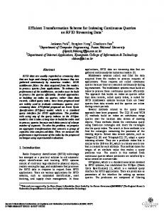
Fig. 1. bank.
H N ,0 ( z ) X ( z )
H N ,1 ( z ) X ( z )
Nth stage
Analysis bank of the perfect reconstruction lattice orthogonal filter
[1], [2] for the lattice orthogonal filter banks. The proposed SPT term allocation scheme produces excellent results when it is incorporated with suitable optimization techniques. II. L ATTICE O RTHOGONAL F ILTER BANK Consider a (2N − 1)-th order lattice structure (with N coefficients) implementing the analysis bank shown in Fig. 1. Let the z-transform transfer functions of the two channels be HN,0 (z) and HN,1 (z), respectively. Thus, � � HN,0 (z) = βN A(αN −1 ) Λ A(αN −2 ) Λ · · · HN,1 (z) � � 1 Λ A(αk ) Λ · · · Λ A(α0 ) , (1) z −1 where N −1 1 1 � , 2 1 + αk2 k=0 � � 1 −αk A(αk ) = , αk 1 � � 1 0 . Λ = 0 z −2 2 βN
=
(2)
It has been proved that the lattice structure of Fig. 1 satisfies the “power complementary property” � � � � �HN,0 (ejω )�2 + �HN,1 (ejω )�2 = 1, (3) and the conjugate quadrature condition in equation (4). H1 (z) = −H0 (−z −1 )z −N .
(4)
Conditions (3) and (4) ensure perfect reconstruction. To determine the lattice coefficients of the filter bank, only the stopband energy of HN,0 (ejω ) should be considered for minimization, since the lattice structure ensures that the
1819
stopband energy of HN,1 (ejω ) is equal to that of HN,0 (ejω ) and is automatically minimized. Moreover, a good stopband of HN,0 (ejω ) ensures a good passband of HN,1 (ejω ), and vice versa. The sensitivities of HN,0 (z) and HN,1 (z) with respect to the coefficient αk denoted by PN,k (z) and QN,k (z), respectively are defined as ∂HN,0 (z) � � PN,k (z) ∂αk (5) = . ∂HN,1 (z) QN,k (z) ∂αk It has been proved in [12] that � � � ∂HN,0 (z) � 1 �≤ � |PN,k (z)| = � < 1, � ∂αk 1 + αk2
(6)
i.e., the smaller the coefficient, the more sensitive the coefficient. III. SPT T ERM A LLOCATION S CHEME The rounding of an infinite precision coefficient value to its nearest SPT value may be modeled as adding an error term to the coefficient value. Suppose that the error term associated with the rounding of the filter coefficient αk is ∆αk . Let the frequency response error of HN,0 (z) in (1) due to the rounding of αk be denoted by Ek,0 (ejω ). For small |∆αk |, Ek,0 (ejω ) may be approximated as Ek,0 (ejω ) = PN,k (ejω ) × ∆αk ,
(7)
where PN,k (ejω ) is given by (5). Therefore, the frequency response error of HN,0 (z) due to the rounding of all its filter coefficients, denoted by EN,0 (ejω ), is given by EN,0 (ejω ) =
N −1 �
PN,k (ejω ) × ∆αk ,
would otherwise cause the largest frequency response error, given by (7). Therefore, ∆αk is initially the value of αk for all k. Once an SPT term is allocated to a particular coefficient, say αm , its corresponding ∆αm is updated accordingly. This procedure is repeated until the total number of SPT terms for the filter is equal to a prescribed number. The SPT term allocation scheme runs as follows: 1) Obtain the infinite precision αk and evaluate the coef1 ficient sensitivity theoretical upper bound Sk = 1+α 2 . k ˆ Let K be the total number of SPT terms to be allocated. Let Kk be the number of SPT terms to be assigned to αk . Initialize Kk = 0 so that ∆αk = αk for all k. 2) Evaluate Ek,0 (ejω ) using Ek,0 (ejω ) = Sk × ∆αk for all k. 3) Let Ei,0 (ejω ) be the largest Ek,0 (ejω ) for all k, i.e., Ei,0 (ejω ) ≥ Ej,0 (ejω ) for all j �= i. ˆ =K ˆ − 1. 4) Ki = Ki + 1, K 5) ∆αi = ∆αi − sign(∆αi ) × 2Li −1 , where 2Li −1 is the power-of-two term nearest to |∆αi |. ˆ = 0, stop; otherwise, go to Step 2. 6) If K 2 In the above SPT term allocation scheme, the theoretical 1 upper bound of the coefficient sensitivity, Sk = 1+α 2 , is k used to evaluate the frequency response error due to the rounding of the corresponding coefficient. The reasons to use the upper bound are as follows: First, numerical example [12] showed that the maximum coefficient sensitivity over all the frequency grids is very close to the theoretical upper bound. It is accurate enough to evaluate the coefficient sensitivity using the upper bound. Second, when infinite precision coefficients are available, it is more convenient and more efficient to calculate the theoretical upper bound than to find the actual maximum coefficient sensitivity. IV. I NCORPORATING THE SPT A LLOCATION S CHEME WITH THE T REE S EARCH A LGORITHM
(8)
k=0
In [2], an SPT term allocation scheme was proposed to allocate SPT terms to coefficients of FIR filters. Initially, all the coefficients are quantized to zero. One SPT term is chosen at a time and allocated to the currently most deserving coefficient to minimize ∆αk (the L∞ distance between the SPT coefficients and their corresponding infinite wordlength values). This process of allocating the SPT terms is repeated until the total number of SPT terms for the filter is equal to a prescribed number. This allocation scheme is suitable for the direct form FIR filters, as coefficient sensitivities for all the coefficients (except the center one) are the same. For the lattice orthogonal filter banks, the coefficient sensitivities vary from one to another. The SPT allocation scheme must consider both the coefficient values and the coefficient sensitivities. In the following discussion, direct rounding technique is used for coefficient quantization. Therefore, if more SPT terms are allocated to a particular coefficient αk , the coefficient rounding error, ∆αk , would be smaller, leading to a smaller frequency response error, which is given by (7). In our proposed SPT allocation scheme, initially, all the coefficients are quantized to zeros, too. One SPT term is chosen at a time and allocated to the current coefficient that
The SPT term allocation scheme proposed in Section III could work alone for the design of SPT coefficient lattice orthogonal filter banks; it also could be incorporated with tree search algorithms to optimize the filter banks further. In [12], a depth-first width-recursive tree search algorithm was proposed to design SPT coefficient filter banks. In that algorithm, each coefficient was allocated with a prespecified number of SPT terms. The tree search algorithm was also suitable for optimizing the lattice filter bank with varying number of SPT terms for each coefficient by incorporating an SPT term allocation scheme. In this section, the tree search algorithm incorporating the SPT term allocation scheme reported in Section III is discussed. In the algorithm described in [12], the infinite precision coefficient solution is the root of the tree. When a node of the tree is created, a pre-defined deterioration measure of the coefficients which have not been quantized are evaluated; the deterioration measure is defined as the product of the coefficient sensitivity and the distance between the upper discrete level and lower discrete level of the continuous coefficient. A child is produced when the coefficient with the largest deterioration measure is fixed to its nearest discrete value with a pre-determined number of SPT terms. The remaining infinite
1820
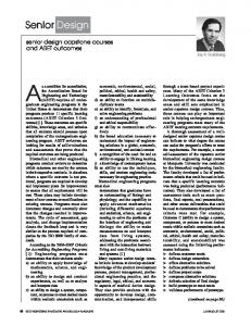
V. E XAMPLES A. Example 1. A series of examples based on the following specifications are selected to illustrate the advantage that can be gained from the proposed allocation scheme over that where all the coefficient are allocated with the same number of SPT terms. Comparisons between the proposed technique and those reported in [1], [2] will also be made. The specifications are: 1) Filter order: 2N − 1 for N ranging from 16 to 40. 2) Stopband edge: ωs = 0.56π. 3) The allowed smallest power-of-two term: 2−10 . In these examples, each coefficient value is either allocated with not more than two SPT terms, or totally 2N SPT terms are allocated to the coefficients using SPT term-allocation techniques so that different coefficient may have a different number of SPT terms. After obtaining the infinite precision coefficients, the coefficients are directly rounded according to SPT term allocation schemes. The stopband attenuation deterioration are plotted in Fig. 2 for N ranging from 16 to 40 for the following cases: 1) Not more than 2 SPT terms are allocated to each coefficient, 2) Using the proposed allocation scheme, an average of 2 SPT terms are allocated to each coefficient, 3) Using the scheme reported in [1], an average of 2 SPT terms are allocated to each coefficient, 4) Using the scheme reported in [2], an average of 2 SPT terms are allocated to each coefficient. Fig. 2 shows that the proposed allocation scheme produced filters with very much smaller deterioration when compared with the allocation scheme where each coefficient is allocated
50 45
2 SPT terms for each coefficient. proposed scheme;
40 Stopband deterioration / dB
precision coefficients are then reoptimized. This procedure is repeated until all the coefficients are quantized and a discrete solution is obtained. When the pre-determined tree width is larger than 1, the tree is branched recurcively by fixing the coefficient with the largest deteriortion measure at the current node to other discrete values with the pre-determined number of SPT terms until a pre-determined tree width is achieved. To incorporate the proposed SPT term allocation scheme to the tree search algorithm, after a node of the tree is created and the deterioration measures of all the unquantized coefficients are evaluated, the SPT allocation procedure described in Section III is performed to all the infinite precision coefficients subject to a total number of SPT terms. This total number of SPT terms is the predetermined total number of SPT terms less the number of SPT terms which have been assigned to the quantized coefficients at the current node. The coefficient with the largest deterioration measure is fixed to the nearest discrete value with the allocated number of SPT terms. The remaining infinite precision coefficients are reoptimized. This particular coefficient may also be fixed to other discrete values with the allocated number of SPT terms in subsequent search until a pre-determined tree width is achieved. In the tree search technique incorprating the SPT term allocation scheme, all children of a node share the same SPT term allocation, whereas the children of siblings have the same number of totoal un-allocated SPT terms, but the SPT terms allocation may or may be the not same.
35
scheme reported in [1]; scheme reported in [2].
30 25 20 15 10 5 0 15
20
25
30
35
40
N
Fig. 2. In the proposed scheme and those schemes reported in [1] and [2], each coefficient values is allocated with a different number of SPT terms such that the average number of SPT terms per coefficient is two.
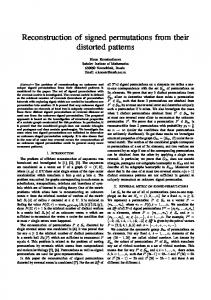
with not more than two SPT terms. The improvement in the reduction of the stopband attenuation deterioration ranges from a few dB to approximately 20dB. The improvement increases with increasing N although the increase is not monotonous. Furthermore, compared with the allocation schemes reported in [1], [2], the proposed allocation scheme produced the smallest deterioration; the maximum improvement in the reduction of the stopband attenuation is more than 6 dB. B. Example 2. An example taken from reference [13] is considered: the stopband edge is at ωs = 0.64π, the filter length is 22 (N = 11), and the total number of SPT terms for the whole filter is 28; in this section, three examples with this frequency response specification are designed. The allowed smallest power of two terms for the three filters are 2−10 , 2−9 and 2−8 , respectively. The tree search algorithm proposed in Section IV incorporating the SPT allocation scheme is used to design these examples. The coefficient values designed using the proposed algorithm are listed in Table I. The CPU-time are 148 s, 177 s and 290 s, respectively, when using a C ++ program running on a 3GHz Pentium 4 PC. The frequency response of the analysis lowpass filter with infinite precision coefficients and finite precision coefficients are plotted in Fig. 3. The allowed smallest power-of-two term for the finite precision coefficients in Fig. 3 is 2−9 . The performance of the filters designed using the proposed algorithm as well as those reported in [13] are tabulated in Table II. From Table II, it is obvious that the proposed algorithm results in a solution with comparable quality much faster than the algorithm proposed in [13]. VI. C ONCLUSION In this paper, an SPT term allocation scheme is developed for the design of lattice orthogonal filter banks where
1821
TABLE I O PTIMIZED SPT LATTICE COEFFICIENT VALUES FOR THE 21 TH ORDER FILTER BANK . 2−10 −2+2 + 2−2 2+0 + 2−3 + 2−7 −2−1 − 2−3 − 2−6 2−1 − 2−3 + 2−5 + 2−7 −2−2 − 2−5 + 2−10 2−2 − 2−4 −2−3 + 2−8 2−4 + 2−7 + 2−9 −2−5 − 2−7 2−6 + 2−9 −2−7 + 2−9
k 0 1 2 3 4 5 6 7 8 9 10
The Smallest Power-of-Two Term 2−9 −2+2 + 2−4 2+0 + 2−2 + 2−6 −2+0 + 2−2 + 2−5 + 2−7 2−1 − 2−5 − 2−7 −2−2 − 2−4 2−2 − 2−5 − 2−7 −2−3 − 2−6 + 2−9 2−3 − 2−5 − 2−7 −2−4 + 2−6 2−5 − 2−7 −2−7
2−8 −2+2 + 2−7 2+0 + 2−2 + 2−5 + 2−7 −2+0 + 2−2 + 2−5 − 2−7 2−1 − 2−5 −2−2 − 2−4 − 2−8 2−2 − 2−5 − 2−8 −2−3 − 2−6 2−3 − 2−5 − 2−7 −2−4 + 2−6 2−5 − 2−7 −2−7
TABLE II S TOPBAND ATTENUATION AND CPU TIME FOR THE DESIGN OF THE SPT COEFFICIENT LATTICE FILTER BANKS OF EXAMPLE 2. Stopband Attenuation / CPU time Allowed Smallest Power-of-Two Term 2−10 2−9 2−8 – 45.19dB / 1.14 h 44.92dB / 2.34 h 46.04dB / 148 s 45.82dB / 177 s 45.29dB / 290 s
Algorithm in [13] Proposed algorithm
0 −4
0
x 10
SPT coefficient design
−10 −0.5
Infinite precision design
Amplitude in dB
−20 −1 −30
0
−40
−45
−50
−50
−60
−70 0
−55
0.05
0.35 0.1
0.1
0.4
0.15
0.45
0.5
0.2 0.3 Normalized frequency
0.4
0.5
Fig. 3. Frequency responses of the analysis lowpass filters of the 21-th order filter bank. The allowed smallest power-of-two term for the SPT coefficient design is 2−9
each coefficient is allocated with a different number of SPT terms. The technique is developed based on the frequency response deterioration due to SPT rounding. The SPT terms are allocated to the coefficients one at a time to minimize the frequency response errors due to rounding the coefficients to SPT numbers. This allocation scheme is superior to those reported in published literatures. R EFERENCES [1] Y. C. Lim, R. Yang, D. N. Li, and J. J. Song, “Signed power-of-two term allocation scheme for the design of digital filters,” IEEE Trans. Circuits Syst. II, vol. 46, pp. 577–584, May 1999. [2] D. N. Li, Y. C. Lim, Y. Lian, and J. J. Song, “A polynomial-time algorithm for design digital filters with power-of-two coefficients,” IEEE Trans. Signal Processing, vol. 50, pp. 1935–1941, Aug. 2002. [3] C. K. C. J. H. Lee and Y. C. Lim, “Design of discrete coefficient FIR digital filters with arbitary amplitude and phase responses,” IEEE Trans. Circuits Syst., vol. 40, pp. 444–448, July 1993.
Language / Machine Used Fortran 95 / 500MHz AlphaServer C ++ / 3GHz Pentium 4 PC
[4] N. Benvenuto, M. Marchesi, and A. Uncini, “Applications of simulated annealing for the design of special digital filters,” IEEE Trans. Signal Processing, vol. 40, pp. 323–332, Feb. 1992. [5] A. Fuller, B. Nowrouzian, and F. Ashrafzadeh, “Optimization of FIR digital filters over the canonical signed-digit coefficient space using genetic algorithms,” in Proc. Midwest Symp. Circuits Syst., South Bend, Indiana, Aug. 1998, pp. 456–459. [6] D. Ait-Boudaoud and R. Cemes, “Modified sensitivity criterion for the design of powers-of-two FIR filters,” Electron. Lett., vol. 29, pp. 1467– 1469, Aug. 1993. [7] C.-L. Chen and A. N. Willson, Jr., “A trellis search algorithm for the design of FIR fiters with signed-powers-of-two coefficients,” IEEE Trans. Circuits Syst. II, vol. 46, pp. 29–39, Jan. 1999. [8] O. Gustafsson, H. Johansson, and L. Wanhammar, “An MILP approach for the design of linear-phase FIR filters with minimum number of signed-power-of-two terms,” in Proc. European Conf. Circuit Theory Design, Espoo, Finland, Aug. 2001. [9] P. P. Vaidyanathan, Multirate Systems and Filter Banks. Prentice-Hall, 1993. [10] B.-R. Horng, H. Samueli, and A. N. Willson, Jr., “The design of twochannel lattice structure perfect-reconstruction filter banks using powerof-two coefficients,” IEEE Trans. Circuits Syst. I, vol. 40, pp. 497–499, July 1993. [11] B.-R. Horng and A. N. Willson, Jr., “Lagrange multiplier approaches to the design of two-channel perfect-reconstruction linear-phase FIR filter banks,” IEEE Trans. Signal Processing, vol. 40, pp. 364–374, Feb. 1992. [12] Y. C. Lim and Y. J. Yu, “A width-recursive depth-first tree search approach for the design of discrete coefficient perfect reconstruction lattice filter bank,” IEEE Trans. Circuits Syst. II, vol. 50, pp. 257–266, June 2003. [13] J. Yli-Kaakinen, T. Saram¨aki, and R. Bregovi´c, “An algorithm for the design of multiplierless two-channel perfect reconstruction orthogonal lattice filter banks,” in Proc. IEEE ISCCSP’2004, Hammamet, Tunisia, Mar 2004, pp. 415–418. [14] Y. J. Yu and Y. C. Lim, “A novel genetic algorithm for the design of a signed power-of-two coefficient quadrature mirror filter lattice filter bank,” Circuit Syst. Signal Process., vol. 21, pp. 263–276, May/June 2002. [Online]. Available: http://www.ntu.edu.sg/home/yuyj/ publicatioin/cssp2002.pdf. [15] P. P. Vaidyanathan and P. Q. Hoang, “Lattice structures for optimal design and robust implementation of two-channel perfect-reconstruction QMF banks,” IEEE Trans. Acoust., Speech, Signal Processing, vol. 36, pp. 81–94, Jan. 1988.
1822