For example, the extraction time in a diffusion percolator may attain 3--4 weeks, while in an extractor containing stirrers it may be several days. High-intensity ...
Chemical and Petroleum Enghzeering, Vol. 36. Nos. 7--8, 2000
RESEARCH, DESIGN, CALCULATIONS, A N D OPERATING EXPERIENCE CHEMICAL PLANT SIMULATING A U-FORM PULSATION EXTRACTOR
UDC 621.69.001.24
R. Sh. Abiev
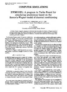
Extractors in current use often represent bottlenecks, as they have extremely low throughput, while they also have substantial sizes. For example, the extraction time in a diffusion percolator may attain 3--4 weeks, while in an extractor containing stirrers it may be several days. High-intensity rotor-pulsation plant tends to be of small size and is used either as flowline equipment or in branches. Also, particles in such an apparatus tend to become excessively reduced in size, so the extract may contain toxic or even poisonous substances. A realistic alternative to such equipment is a resonant pulsating one [I ]. Experiments with such plant have shown that the process takes much less time while increasing the degree of extraction by 15-20% and saving considerable amounts of energy [2]. A qualitative analysis of the capillary impregnation in the particles, which usually accompanies extraction, shows that it is best to conduct the process at relatively low pressure oscillation frequencies (a few Hz) [3, 4]. Efficient extraction from a connected-pore material requires unsymmetrical pressure oscillations [4] and turbulent motion of the liquid between the particles. Automating liquid pressure under the best conditions provides for extracting the material efficiently from the particles and reduces the internal transport resistance, while the turbulence between the particles reduces the external diffusion resistance. These requirements are fully met by the Fig. 1 resonant U-tube pulsation plant. The symmetrical construction consists of two cylindrical sections 1 having perforated bases 2 and connected by the tube 3. There is gas above the liquid in both sections, which acts as an elastic component in the oscillatory system. The elastic element 4 under the piston 6 is active, while element 5 under the blank seal is passive. In the initial state, the particles 7 form a dense layer on the base plate 2. The reciprocating piston produces the following processes. As the piston moves downwards, the gas under it is compressed, and the liquid in the fight-hand section filters through the channels between the particles and rapidly accelerates. In the left-hand section, the particles are fluidized almost immediately (calculations are given below), which produces good mixing and eliminates the diffusional boundary layers from the particles. Potential energy accumulates in passive elastic element 5, and when the piston moves in the reverse direction, it returns to the system and displaces the liquid from the left-hand section into the fight-hand one. The suspension in the left-hand section settles out quite rapidly and the liquid begins to pass through the channels there, while fluidization occurs in the right-hand section, i.e., in each period of the reciprocating piston motion, there are alternating processes of infiltration and fluidization. Good mixing is thus provided by the liquid pressure oscillations. The following forces act on the suspension: - the pressures from the gas in the elastic elements 4 and 5 (Fig. 1); - the interaction between the particles and the liquid; and - the inertia of the liquid and particles, including effects from the adjoint mass. A complete mathematical description of the oscillations is fairly complicated. To simplify the analysis, we examine the order of the quantities influencing the suspension dynamics. St. Petersburg State Technical University. Translated from Khimicheskoe i Neftegazovoe Mashinostroenie, No. 8, pp. 11-14, August, 2000. 0009-2355/00/0708-0471 $25.00 02000 Kluwer Academic/Plenum Publishers
471
o
5-'~
[~
: "t'.'~
7-
4
I B ~. ~ % , , ~
-'-'-"" "a'.
~
9 9 I
-_- = , , , ,,.
r..-_-.
'.:-:;-:-:',1 , I 9 9 ." ."%." ;:: [--_-,-: 1 / -
--~.
"-..-"'...1
Fig. 1. Scheme for U-tube pulsating extractor: 1) cylindrical section; 2) perforated baseplate; 3) connecting tube; 4 and 5) active and passive elastic elements; 6) piston; 7) particles.
Let piston 6 reciprocate harmonically: Zp = ( L p / 2 ) s i n ( o~t),
( 1)
where Lp is the total piston stroke, co the angular frequency, and t the time. In the unperturbed state (with Zp = 0), the volumes V 1 and V2 of the gas-filled passive and active elements respectively are identical: Vto = V2O.
(2)
The pressures Pl and P2 in those elements are also' identical in the unperturbed state: Pl0 = P20-
(3)
Conditions (2) and (3) provide symmetry with nonlinear variations in the pseudoelastic forces [5]. However, to retain generality, we assume that (2) and (3) may not be obeyed. For any displacement x of the liquid surface, the volumes of the elastic elements are Vl = V10- xSa;
(4)
V2 = V20 + x S a - zSp,
(5)
where S a and Sp are the areas of the apparatus and piston respectively. We take the pressure variations in the elastic elements as isothermal: Pl = PIoVIo/V1;
(6)
P2 = P20 V20 / V2"
(7)
Then the resultant of the perturbing and pseudoelastic forces due to the differences in pressure on the liquid in the two sections is Fr = (P2 -Pl)Sa" 472
(8)
-#.5, O
0.5
I.O
1.5
ZO
Z.5
z"
Fig. 2. Dependence of the dimensionless coordinates of the piston Z-p and liquid front s together with the liquid velocity ii on time z.
fit, ,OZ,z~,O, MPa
~-
-!.10 5 0
O.t
-o.~
0.$
LO
1.5
Z.O
Z.5 ~"
Fig. 3. Time course of pressure in active and passive elastic elements together with pressure difference Ap and the f u n c t i o n f
The second force is that between the phases, and in the section in which the liquid descends, it is determined by the infiltration conditions, while in the section where the liquid is rising, it is determined by the fluidization ones. In the first case, the pressure difference across the layer of suspension of height H is given by Erg-un's formula [6] as
(9) where A, = 21a s2(l -e)2~283 H;
B, = 0.7 s ( l - e)91~38~ 3 H;
~t is dynamic viscosity, s the specific surface of the particles, e the porosity of the dense particle layer (e = 0.45), 91 the density of the liquid, and ~ a factor representing the sinuosity of the particle channels (~ -- 1.5). The pressure difference across the fluidized bed of height H is Apt,,o = [91 ~ + 92(1 - 8)]gH,
(10)
where 92 is particle density and g the acceleration due to ~avity. Estimates of this difference show that it is about 104 Pa for H = 1 m. The parameters characteristic of plant materials such as ~ o u n d pine cones or medicinal herbs and roots are s = 103 m -l, 91 = 785 k ~ m 3, 92 = 942 k ~ m 3, and ~t = 1.1-10-3 Pa-sec, in which case Ap, is larger by an order of magnitude, i.e., for a pressure amplitude in the elastic elements of about 105 Pa, the fluidization in the rising flow and the deposition in the descending one occur almost instantaneously. Also, one can neglect the pressure losses in the fluidized bed in approximate calculations. 473
We now specify the amplitude and frequency of the oscillations: A = 0.02 m and f = 1 Hz. The amplitude of the liquid velocity is A v = (dx/dt)ma x = 2 n f A = 0.126 m/sec. Substitution into (9) shows that the first term, which characterizes the laminar infiltration, can be neglected. Also, the frictional losses in the connecting tube are small by comparison with the infiltration losses. That description shows that the particles are immobile in the infiltration section, and the inertial force is Fi! = SaHpted2x/dt2; in the other section, where there is fluidization, the particles and liquid move with similar velocities, and the inertial force is Fi2 = S a i l [ p i e + P2(l - s
2. The inertial force of the liquid in the connecting tube is
Fi3 = S t L t P l ( D I d ) 2 d 2 x / d t 2, in which S t and and L t are the cross section and length of that tube, whose diameter is d. Then the m o v i n g mass referred to the cross sectional area S a of the apparatus of diameter D is M = SaH[2pfi + P2(1 - e)] + S t L t P l ( D / d ) ' . Then the following is the equation of motion for the suspension due to the piston oscillation Zp(t) on the above basis: ,)
dt 2 -
r-Bq~Sa
or from(4)--(8), M d2x P20 V20 S a dt 2 = V 2 0 + x S a - z p ( t ) S p
Plo VIO VIo-XS a
dd.r) 2 I, d t ] "
(11)
The second-order nonlinear differential equation (11) contains the inertial forces, the nonlinear pressure forces, the perturbing force, and the quadratic resistance force. We can now estimate the terms in (11) for these parameters: for the apparatus H = 1 m; D = 0.273 m, for the tube Lt = 0.7 m, d = 0.08 m, and for the elastic elements VI0 = V20 = 4.42-10 -3 m3; PI0 = P20 = 105 Pa. The amplitude of the suspension acceleration is A a = (d2x/d~)max = (2nf)2A = 0.79 m/sec 2. The maximum value for the quadratic resistance with these parameters is B~(Aa)2 = 1.007.105 Pa, while the maximum inertial pressure is M A a / S a = 1.43-103 Pa, i.e., less by two orders of magnitude, so in the main the force due to the gas compressed in the elastic elements is consumed in overcoming the infiltration resistance. Then ( 11 ) may be rewritten as follows on the basis that the inertial forces are small:
u
(12)
qB,
where Ap(x,t) =
P20 V20 V20 +xS a - Zp(t)Sp
PloVIo VIO - xS a
is the pressure difference between the active and passive elastic elements. The nonlinear ordinary differential equation (12) has been solved by means of a fourth-order Runge-Kutta method with initial condition x = 0 for t = 0. Figure 2 shows results for Sp = Sa, Lp = 0.08 m in the dimensionless coordinates ~p = Zp/Xma x, X = X/Xma x, ff = u/(coL/2), and x = 2rot~to, in which Xmax is the maximum displacement of the liquid surface and u is the flow speed. From the second steady-state oscillation period onwards, the lines for the liquid displacement and speed of the front are shifted in phase by n/2. Also, there is a phase shift between the displacement of the liquid and the piston by about rd3, which is due to the substantial infiltration resistance. In (12), the inertia is taken as negligible, so the lag in the phase of the liquid surface should not be dependent on the frequency, as is confirmed by the calculations. An analogous shift occurs between the pressure curves (Fig. 3) for the active and passive elastic elements, together with the pressure difference 3 and the function f = 0.1sin(2nx) corresponding to the piston displacement. There is some advance in the phase of P2 in the active element by comparison with f because the liquid cannot descend as rapidly as the piston and the 474
f)'VJ/\'V _,; d vm vm _,., \ / O
0.5
\i
I.g
L5
\7
,~.0
L5
Fig. 4. Dimensionless quantities referred to the maximal values in the time dependence of the piston velocity ~p, force/Sp acting on the piston, and power A/p supplied to piston.
pressure rises somewhat more rapidly than the piston displacement. Also, the peaks are sharp and the minima in if(x) are flattened in Fig. 2 and in pl(x), p2(x), and Ap(x) in Fig. 3 because the (6) and (7) pressure variation laws are nonlinear. Other major parameters are the load on the piston and the power consumed. The instantaneous force applied to the piston is Pp = (,o2 - 105)Sp. The instantaneous power supplied to the piston is
Np = Ppup, where Up = dzp/dt is the piston's instantaneous speed. With these parameters, the maximal values of the force and power are Pp = 3.8 kN and Np = 584 W, which are quite reasonable for a prototype plant of volume about 100 liter. The phases of the piston's velocity and the force acting on it are displaced by about ~ 2 (Fig. 4), as for linear systems. The instantaneous power has a doubled frequency, which applies only forP20 = 105 Pa. The specific dissipation representing the input power for these conditions is e 0 = Np max/M 0 = 5.5 W/kg, in which M 0 is the total mass of the suspension, whereas the figure for an extractor containing a stirrer is 10 W/kg. Comparative tests show [7] that the extraction rate in this apparatus for the same specific energy consumption is several times higher than that in an equipment having a turbine stirrer. This is due to the substantially greater penetration of the liquid into the particles. The following is the Reynolds number derived from the maximal velocity Umax in the channels between the particles with the above parameters: R e k = 4eUmaxP--I = 37,
s(l - e)~t which corresponds to a moderate level of turbulence in the space between the particles. The two requirements formulated above as necessary for normal operation can thus be provided in this apparatus with relatively low energy consumption. The simplified equation (12) has been derived on the basis of low inertia for a comparatively small extractor. With a large apparatus, one cannot neglect the inertial forces, and one should solve (12) with the second derivative of the displacement. Then one can realize a state close to the classical resonant one [8], in which the potential energy of the compressed gas and the kinetic energy of the moving liquid are interchanged twice during a period, while the piston's input energy is almost completely dissipated in the infiltration. These calculations indicate as follows. 9 If the particles are large enough, the damping of the oscillations in such an equipment because of the turbulence in the liquid infiltration is extremely great at usable frequencies and amplitudes. 475
9 The specific power dissipation is comparatively low, and provides a considerable pressure amplitude, which guarantees deep penetration into the pores, and also good circulation at the particle surfaces. 9 The proposed design is a realistic alternative to existing extractors containing stirrers or rotational pulsating ones.
REFERENCES I.
2. 3. 4. 5. 6. 7. 8.
476
R. Sh. Abiev, E. G. Aksenova, and G. M. Ostrovskii, "New developments in resonant pulsating plant for liquid systems;' Khim. Prom., No. 11,764-766 (1994). S. N. Vasil'ev, R. Sh. Abiev, V. I. Roshchin, et al., "Kinetic regularities in extracting biologically active substances from woody plants," l~estiya VUZ, Lesnoi Zhurnal, No. 5-6, 126-131 (1994). G. M. Ostrovskii, A. Yu. Ivanenko, and E. G. Aksenova, "Impregnating through capillaries by periodic pressure variation," Teor. Osn. Khim. Tekhnol., 29, No. 6, 607-611 (1995). R. Sh. Abiev, "Impregnating capillaries with constant or variable pressures in liquids" Zh. PriM. Khimii, 67, No. 3, 419-422 (1994). R. Sh. Abiev, "Determining the best geometry for the elastic elements in a U-tube liquid apparatus," Khim. Neff. Mashinostr., No. 1, 8-13 (1998). M. I~. Aerov and O. M. Todes, Hydraulic and Thermal Principles in Equipment Containing Stationary or Fluidized Beds [in Russian], Khimiya, Leninvad (1968). S. N. Vasil'ev, R. Sh. Abiev, V. I. Roshchin, and G. M. Ostrovsldi, "'Fractionating mixtures o f natural compounds containing polyprenols and isoabienol by liquid extraction," Izvestiya VUZ, Lesnoi Zhurnal, No. 1, 96-100 (1998). I. I. Bykhovskii, Principles of Vibrational Engineering Theory [in Russian], Mashinostroenie, Moscow (1968).