section 8.1.10 entitled "Electronic Information Dissemination". At the time ... Xiang Gui, Member, IEEE, James W. Haslett, Senior Member, IEEE, Steven K. Dew,.
©1998 IEEE. Personal use of this material is permitted. However, permission to reprint/republish this material for advertising or promotional purposes or for creating new collective works for resale or redistribution to servers or lists, or to reuse any copyrighted component of this work in other works must be obtained from the IEEE.
Copyright and all rights therein are retained by authors or by other copyright holders. All persons copying this information are expected to adhere to the terms and constraints invoked by each author's copyright. In most cases, these works may not be reposted without the explicit permission of the copyright holder.
This copyright notice is taken from the IEEE PSPB Operations Manual, section 8.1.10 entitled "Electronic Information Dissemination". At the time of this notice, this section is posted at http://www.ieee.org/portal/index.jsp?pageID=corp_level1&path=about/docu mentation/copyright&file=policies.xml&xsl=generic.xsl
380
IEEE TRANSACTIONS ON ELECTRON DEVICES, VOL. 45, NO. 2, FEBRUARY 1998
Simulation of Temperature Cycling Effects on Electromigration Behavior Under Pulsed Current Stress Xiang Gui, Member, IEEE, James W. Haslett, Senior Member, IEEE, Steven K. Dew, and Michael J. Brett, Member, IEEE
Abstract—The temperature cycling effect on electromigration behavior under pulsed current conditions for metallization used in very large scale integrated (VLSI) devices is numerically investigated. This involves the solution of a two-dimensional (2-D) heat-conduction equation and a one-dimensional (1-D) diffusiondrift equation. We find that the characteristic thermal response time for establishing the equilibrium, for a typical VLSI metallization structure, is slightly longer than 1 ms. As a result, the steady-state temperature difference in the metal line between the upper and lower values in response to the pulsed current operation is maximized when the frequency is below 250 Hz with a duty factor of 0.5. The temperature difference decreases with increasing frequency. At frequencies above 10 MHz, the thermal capacity of the metal line inhibits appreciable temperature fluctuation. For a constant line temperature the time-dependent vacancy buildup has been shown to be proportional to rm with m = 2 (where r is the duty factor), consistent with the “average model” for predicting the failure time. In this study, we confirm the speculation that Joule heating due to an elevated current density employed in accelerated life testing can bring about an m < 2 dependence at low frequencies. The confirmation is based upon the solution of the electromigration initial and boundary value problem by taking into account the temperature dependence of several relevant physical parameters, particularly the vacancy diffusivity. Index Terms—Diffusion processes, electromigration, integrated thermal factors, metallization, numerical analysis, transmission line matrix methods.
I. INTRODUCTION
T
HE phenomenon of electromigration, or material movement resulting from the passage of an electrical current, continues to be a major reliability concern for the interconnects in very large scale integrated (VLSI) circuits. Longer electromigration lifetimes have been observed for metal lines subjected to pulsed current stress rather than to constantly flowing direct current (dc) stress and various possible mechanisms were proposed by many workers [1]–[12]. As most interconnects carry pulsed signals, it is important to have an improved understanding about the nature of the problem so as Manuscript received March 31, 1997; revised August 20, 1997. The review of this paper was arranged by Editor A. H. Marshak. This work was supported by the Natural Sciences and Engineering Research Council of Canada. X. Gui and J. W. Haslett are with the Department of Electrical and Computer Engineering, The University of Calgary, Calgary, Alta. T2N 1N4, Canada. S. K. Dew and M. J. Brett are with the Department of Electrical and Computer Engineering, University of Alberta, Edmonton, Alta. T6G 2G7, Canada. Publisher Item Identifier S 0018-9383(98)00939-3.
to assess adequately the enhancement of the electromigration lifetime. The Black empirical expression [13] for median time to failure (MTF) is well known as a standard dc electromigration equation. It is convenient to describe the research background of pulsed dc electromigration by using this equation in a modified form MTF
(1)
where is a material and geometry dependent constant, is the current density, is the duty factor, is the activation energy, is the Boltzmann constant, is the temperature, is the current density exponent normally assumed to be 2, and is the duty factor exponent. The value of is of particular interest because it is employed for characterizing the lifetime enhancement due to pulsed operation. There are two different models generally referred to as “on-time” and “average” models. is assumed in the on-time model, so that the MTF is inversely proportional to the duty factor This means that the current-induced material transport is a function only of the total “on” portions of a repetitive current pulse while there are no effects during the times when the signal is “off.” The concept of the on-time model was proposed to give a conservative approach for VLSI interconnect design [14], [15]. Alternatively, the average model [3], [4] assumes , so that the dc equivalent current is given by the magnitude of the current averaged over the entire period (i.e., Clearly, suggests a relaxation process which occurs during the off times. Many workers [3]–[6] have found that the results based on are in good agreement with experimental data. Based on the fundamental diffusion-drift model with the assumption of a constant interconnect temperature, the electromigration initial and boundary value problem under pulsed current conditions has been solved numerically and the conclusion of was also obtained [8], [12]. Furthermore, we have demonstrated that the “pure” electromigration-induced vacancy buildup (excluding the influence of Joule heating) under a pulsed dc stress can be described accurately by the dc stress scaled according to this duty factor dependence [12]. A recent theoretical investigation [11] has even shown that the MTF is proportional to for an arbitrary periodic stress (unidirectional but not necessarily to be rectangularly-
0018–9383/98$10.00 1998 IEEE
GUI et al.: SIMULATION OF TEMPERATURE CYCLING EFFECTS ON ELECTROMIGRATION BEHAVIOR
pulsed). On the other hand, several experimental studies [6], [7], [9], [10] supported an or dependence if the pulse repetition frequency is below a certain value. This can be qualitatively explained by nonlinear thermal effects. At sufficiently high frequencies, the interconnect temperature would remain constant because the pulse repetition time is much shorter than the thermal response time. This allows electromigrating material to substantially relax during the off portion of the pulse. In contrast, the fluctuation of temperature at low frequencies might retard the back diffusion during the cooler off portion. Practically, it is extremely difficult, if not impossible, to measure the transient temperature response of the metallization line accurately. Therefore, computer simulation is very desirable to confirm these speculations. In the present study, we perform a quantitative computation of electromigration behavior under pulsed current stresses, taking into account the effects of frequency dependence of temperature response. In the next section, we determine the maximum difference in interconnect temperature between on and off times at steady state as a function of the pulse repetition frequency for a typical VLSI metallization structure. This requires the solution of a two-dimensional (2-D) time-dependent thermal diffusion equation. In Section III, we incorporate such information into the vacancy supersaturation model for electromigration failure, which involves the solution of the one-dimensional (1-D) electromigration (diffusion-drift) equation in order to evaluate the influence of temperature cycling. The transmission-line matrix (TLM) techniques [12], [16], [17], along with the newly developed boundary treatment [18] are used for numerically solving all these equations. Finally, a summary of the results is given in Section IV. II. THERMAL MODEL: FREQUENCY DEPENDENCE OF TEMPERATURE RESPONSE In a digital VLSI circuit, a number of fairly long metallization lines are usually arranged in parallel to carry signals. Fig. 1(a) shows such a structure. We assume that the Al lines are 0.75 m thick by 0.8 m wide and equally spaced by 4.0 m between centers. These lines are deposited onto a 1.0m thick layer of SiO grown on a 300- m thick Si wafer. The lines are buried under 1.5 m of planarized SiO passivation layer. The electrical current flows through the Al lines and creates the Joule heating, , where is the current density and is the electrical resistivity. The temperature dependence of for Al is considered in the model according to
381
(a)
(b)
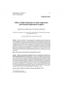
Fig. 1. (a) Parallel Al metallization lines encapsulated with SiO2 on a Si substrate. (b) Elemental cross section through the structure used in the simulation. Symmetry is exploited to reduce the computation. TABLE I SOME PHYSICAL PROPERTIES OF MATERIALS USED IN THE SIMULATION
conduction paths through passivation material) than can be a 1-D model. Second, the longitudinal temperature distribution perpendicular to the plane of Fig. 1(b) is ignored so as to emphasize the periodic temperature effect itself rather than others originating from temperature gradients. Meanwhile, intensive computer run time can be avoided with the simplified geometry as the calculation for temperature response to a repetitively-pulsed stress could be very time consuming. The governing heat-flow equation is given by (3) where is the density, is the specific heat, is the thermal conductivity, and is the time. The physical parameters for the materials used (Al, SiO and Si) are listed in Table I. Current density is a constant under the dc condition, and is periodically changed for a pulsed dc stress according to for for
(2)
(4)
cm/K [19]. with the constant being equal to A 2-D thermal analysis of a cross-sectional element as shown in Fig. 1(b) is conducted to reduce the computational effort. The top surface is approximated to be adiabatic and all sides represent the symmetry faces with zero gradient in temperature across the boundary. The back contact of the chip is held at an ambient temperature of 200 C The model geometry being chosen as such is based on several considerations. First, it is a 2-D model and thereby more accurate and complete (e.g., the inclusion of the heat-
where is the pulse duration, is the period, and is the period sequence number. The duty factor is defined as The temperature response versus time is calculated at a variety of different pulse repetition frequencies for sufficient time to achieve a steady-state cyclical condition. For the metallization structure described above, calculated results indicate that the Joule-heating-induced temperature rise is not appreciable for a current density of the order of 10 A/cm , and is about 2 C for A/cm at steady state. For higher current densities, the Joule heating
382
IEEE TRANSACTIONS ON ELECTRON DEVICES, VOL. 45, NO. 2, FEBRUARY 1998
(a) Fig. 3. Maximum temperature difference between on and off portions of the pulse at steady state versus the pulse repetition frequency (current density j = 2 :5 106 A/cm2 , duty factor r = 0:5).
2
(b)
(c) Fig. 2. Temperature variation of Al lines versus time due to a pulsed dc current stress at different frequencies (current density j 2:5 106 A/cm2 , duty factor r = 0:5). (a) 250 Hz. (b) 10 kHz. (c) 1 MHz and 10 MHz.
=
2
increases rapidly. Therefore, we choose A/cm as a plausible value to show our results, which is also typical in many traditional accelerated electromigration tests. Displayed in Fig. 2(a)–(c) are the simulation results of the temperature response within the Al lines at various frequencies. The magnitude of the thermal time constant is found to
be of the order of ms. For longer heating or cooling times we can expect to obtain a maximum difference in line temperature under steady-state pulsed excitation. If we consider a factor of 90 per cent of the temperature rise or decay, then the time scale for both on and off intervals can be approximated by 1 ms, corresponding to a repetition frequency of 500 Hz with a duty This steady-state establishing time is consistent factor with that in an early report [20], where the 1-D calculation of temperature distribution along the metallization line under dc stress is performed. Our more accurate calculations with respect to the 2-D structure indicate that 2 ms [or a frequency , see Fig. 2(a)] would allow the upper of 250 Hz with and lower line temperatures to approach the equilibrium value for a continuous current stressing and to return to the ambient temperature when the current is switched off. Consequently, the temperature difference is maximized and will remain as a constant for even lower frequencies. In the present case, this temperature difference is slightly greater than 12 C In other words, the line temperature varies between 200 and 212 C periodically at any frequency below 250 Hz. Fig. 3 shows the maximum temperature difference between on and off times as a function of the pulse repetition frequency. There is a large temperature drop in the frequency range from 250 Hz to about 10 kHz and the temperature variation decreases steadily as the frequency further increases. Eventually, after the frequency is above 10 MHz, the thermal capacity of the metal line inhibits any obvious change in the line temperature. As a result, the line temperature is stabilized to an average value, and the relevant temperature fluctuation effects would be negligible. Although a particular metal line geometry is employed in this study, the conclusions drawn above regarding the frequency dependence of temperature response do not appear to be significantly different for other realistic line sizes used in VLSI metallization. From the thermal point of view, current density is the most important parameter in determining the temperature rise within the metal line. For carrying the same current, a more “aggressive” design using a smaller line dimension (e.g., in the deep sub-micron range) will increase
GUI et al.: SIMULATION OF TEMPERATURE CYCLING EFFECTS ON ELECTROMIGRATION BEHAVIOR
current density and temperature rise. On the other hand, when the current density is the same, a smaller cross-sectional area represents a less power dissipation and will alleviate heat generation. A further relevant factor in thermal considerations is the SiO layer between the metal line and the Si wafer. A thinner SiO layer would be helpful to reducing the metallization thermal resistance and heat dissipation [21]. III. DIFFUSION-DRIFT MODEL: VACANCY SUPERSATURATION BEHAVIOR WITH NONLINEAR HEATING The electromigration initial and boundary value problem can be examined by the following continuity equation [22] for a diffusion-drift system (5) with (6) where is the vacancy concentration, is the effective ionic charge, is the grain-boundary self-diffusivity which has an Arrhenius temperature dependence with being the preexponential factor (7) The parameter whose reciprocal is directly related to the Blech length [23], characterizes the reduced electromigration driving force. Equation (5) is subject to an initial uniform vacancy concentration (8) along with the completely blocking (zero diffusion flux) boundary condition at (9a) and a constant vacancy concentration at (9b) Equations (9a) and (9b) represent a set of standard boundary conditions with reasonable physical meaning [24]. Vacancies would migrate from the supplying end at (such as a bonding pad) to the blocking end at (a contact) and accumulate there with the elapsed stressing time. The vacancy concentration will be saturated ultimately at the blocking boundary. If the quantity is sufficiently large (Blech length effect [23]), a critical value of the vacancy concentration may be reached before the occurrence of the saturation and a void formation will be initiated. Otherwise, the metallization line would be virtually immune to the electromigration damage. Clearly, the variation of vacancy concentration at the blocking boundary is of special interest for predicting failure time. Based on the above formulation, there is no macroscopic diffusion phenomenon at the very beginning owing to the initial
383
uniformity of the background vacancy concentration. However, the current-induced electromigration quickly changes the distribution of the vacancy concentration, and both drift (due to the electric field) and diffusion (due to the concentration gradients) come into play. In the off portion of the current pulse, there is only the diffusion process which tends to restore the migrated vacancies toward their original position and balance the vacancy distribution. One of the problems with simulations applied to the pulsed electromigration phenomena is that the modeler must consider two incompatible time scales simultaneously as the pulse period is very short compared with the time to failure. For high frequencies both the time step and the spatial resolution of a numerical method have to be made very small, which could bring about a prohibitive computational cost. However, there are appropriate ways to get round this difficulty. We have shown in [12] that the monotonical convergence of the vacancy concentration with increasing frequency allows reasonable conclusions to be drawn before the computation becomes intensive. Section II shows that above 10 MHz and below 250 Hz represent two distinct regions from the thermal point of view. In the present model, the parameter is a function of current density electrical resistivity , and temperature Notice that is varied with time according to the signal frequency and duty factor, and change at different , and depends on the created Joule heating. In order to highlight the temperature cycling effect, we calculate the vacancy concentration versus time at a very low frequency of 1 mHz with a duty factor of Although this frequency itself may not be so interesting in practical circuits, it is of assistance in characterizing the low-frequency behavior due to temperature effects. As the steady-state temperature field can be established in the order of 10 s, it would be appropriate to assume two constant temperatures, a high one and a low one , for the on and off portions of the waveform. Such treatment only very slightly enhances the effect to be simulated but greatly simplifies the matter. According to the solution of temperature response presented in the preceding section, and are A/cm 212 and 200 C, respectively, when In the calculation, cm s, and eV [23], [25] are assumed. The results are shown in Fig. 4. Here, the power is cycled a very large number of times to reach the steady state, with the temperature and associated parameters and varying 10 periodically. We have also plotted the high frequency MHz) curve in the same diagram for comparison, which is produced under an equivalent dc current stress scaled down by the pulsed current and duty factor A/cm [12]. As expected, the low-frequency curve with the temperature fluctuation is situated above the high-frequency curve where a constant average temperature of 206 C is assumed, giving rise to a higher vacancy concentration at the same stressing time. It has been shown [26] that the failure time is normally dominated by the void incubation process described by the vacancy supersaturation model instead of its subsequent rapid growth. As an example, one may assume that the ratio between
384
IEEE TRANSACTIONS ON ELECTRON DEVICES, VOL. 45, NO. 2, FEBRUARY 1998
Fig. 4. Vacancy buildup as a function of time at frequencies above 10 MHz 2:5 106 A/cm2 ; duty factor and below 250 Hz (current density j r = 0:5).
=
2
the critical vacancy concentration and the initial background is equal to four. With this ratio, the failure time value at the low frequency is found to be approximately s and that at the high frequency is doubled. Furthermore, if is equal to five, then the metallization line can survive for about 10 s at the low frequency while it will never fail under high-frequency operation. In Fig. 5, the vacancy buildup behavior is shown as a function of time scaled by the duty factor and its exponent, for , , and . All the curves are obtained under an identical peak current density of A/cm As already mentioned, a low frequency of 1 mHz is used for the pulsed current, and the dc stress is applied at a constant average line temperature of 206 C One can see that the level at which the vacancy concentration saturates increases with increasing since a greater means a longer time to apply the current stress for the same value of period. for the In this simulation, we tried different values of various in such a way that all the curves become coincident below saturation. The coincidence with assuming the same critical concentration implies that the vacancy buildup is , or an dependence can be seen proportional to to initiate electromigration failure. It has been shown that gives the best fit to the coincidence at a constant line temperature (high-frequency case) for different values of [8], [12]. An dependence in the lifetime enhancement would be expected at low frequencies due to the temperature cycling effect. As shown in Fig. 5, such a dependence is indeed is found obtained. For the reason of thermal nonlinearity, , and a somewhat greater value of 1.6 is to be 1.5 for exhibited for Fig. 6 is a more complete diagram, showing the temperature difference between on and off states and the resultant value variation for a frequency below 500 Hz with These calculations under a typical range of accelerated current-density stress conditions are performed by using the same approach as detailed above. We find that the value of decreases with the increase of the current density from A/cm onwards. A current density of A/cm
Fig. 5. Vacancy buildup as a function of time for several values of r (current density j = 2:5 106 A/cm2 ). The curves for the pulsed cases correspond to a frequency lower than 250 Hz. Notice that the time axis is scaled by multiplying a factor r : In the region below saturation, the vacancy buildup with time is proportional to r with m < 2:
2
m
m
leads to a temperature difference near 25 C and can be deduced from these data, which follows the on-time model. It is thus clear that the or dependence is observable experimentally and that the concrete value of depends strongly upon the temperature difference, which in turn varies with current density, test (oven) temperature as well as sample structure. This could be one reason why the reported transition region of frequency between the average and on-time models is far from consistent [6], [7], [9], [12]. On the contrary, the frequency value above which the average model holds true is comparatively independent of the strength of the applied stress because of the attainment of a stable temperature within the metal line. The frequency of greater than 10 MHz obtained in this study is in the same range as that reported elsewhere [9], [10]. The variance of the value with current stress and operating frequency can be shown by a numerical example based on our calculation. As already seen, a temperature difference of 12 C induced by A/cm and 25 C by A/cm at low frequencies with result in and , respectively. However, the temperature difference is negligibly small 0.5 C at both current densities if the pulse repetition frequency is above 10 MHz with the same duty factor, resulting in an identical dependence. Based on the present electromigration model, the vacancy concentration at the blocking boundary depends on the integrated current density which tends to the average value at a constant line temperature for commonly-used frequencies. The time to failure, as a result, scales as It is worthwhile to note that an dependence at sufficiently low frequencies may possibly be found even in the absence of the temperature cycling effects. This has been illustrated by a similar model within the diffusion-drift framework [27] and may also be produced by a totally different vacancy relaxation model where a fitting parameter based on experimental data is used [28]. However, a large deviation of the vacancy concentration from the average level to reach the critical ratio is observable only when there is a small number of vacancy-concentration
GUI et al.: SIMULATION OF TEMPERATURE CYCLING EFFECTS ON ELECTROMIGRATION BEHAVIOR
Fig. 6. The value of m and the temperature difference as a function of current density at frequencies below 250 Hz with a duty factor of 0.5.
oscillations in response to the pulsed current waveform up to the time of failure. The corresponding frequencies have been shown to be very much lower than 1 mHz for Al metallization [12]. Careful inspection of Figs. 4 and 5 reveals that such an oscillatory behavior (tightly around the average level) at a frequency of 1 mHz is actually exhibited while its apparent smallness is also demonstrated. As a frequency greater than 1 mHz would result in even smaller vacancy-concentration oscillations, the use of this value as an example frequency to show the temperature cycling effects can be justified. The deduced -value variation has therefore been attributed solely to the temperature cycling effects which are the main subject of the present study. Finally, we emphasize that the conclusions drawn in this section are only strictly valid under two basic assumptions of the vacancy supersaturation model. First, the void incubation process dominates the entire failure time. Additional studies would be necessary if this assumption were not used for the application of the on-time and average models at different operating frequencies. Second, the present model, which is based on the fundamental diffusion-drift transport mechanism, essentially incorporates grain-boundary kinetic parameters in a continuum form but does not take into account microstructural details of the thin metal film. For narrow VLSI interconnect lines with a near-bamboo microstructure, the responsible failure mechanism may be complicated by the coexistence of polycrystalline clusters and bamboo segments. Relevant implications on both the and values are still under further assessment and investigation. IV. CONCLUDING COMMENTS In summary, we have investigated the temperature cycling effect on electromigration behavior under pulsed current stresses by numerically solving two partial differential equations governing the physical processes. The temperature fluctuation has been given as a function of the pulse repetition frequency. We found that the metallization temperature remains at an average constant value at an operating frequency
385
above 10 MHz for a representative system. Under the condition of a constant temperature, the average current density model with for the duty factor is valid. On the other hand, the temperature oscillation in metallization lines reaches a maximum amplitude when the frequency is lower than 250 Hz. In this study, we confirmed the speculation that an dependence can be obtained at a low frequency due to the temperature dependence of several physical parameters, including the vacancy diffusivity and electrical resistivity of the metal lines. In addition, we found that a current density of the order of 10 A/cm does not create appreciable Joule heating within the metallization. Therefore, the temperature cycling effects (and dependence) may only be of the deviation from the much concern in accelerated life testing. Moreover, it should be noted that significant heat generation due to a high current density stressing can alter the value of in (1) as well. In order to obtain more reliable data that would be extrapolated to normal working conditions for lifetime estimation, a current density not excessively greater than that used in the real-life operation (e.g., below A/cm is recommended for those tests whenever possible. Finally, test structures should be designed appropriately to minimize severe Joule heating effects that may not be a factor under normal device operation. REFERENCES [1] A. T. English, K. L. Tai, and P. A. Turner, “Electromigration in conductor stripes under pulsed dc powering,” Appl. Phys. Lett., vol. 21, pp. 397–398, 1972. [2] J. M. Schoen, “A model of electromigration failure under pulsed condition,” J. Appl. Phys., vol. 51, pp. 508–512, 1980. [3] J. M. Towner and E. P. van de Ven, “Aluminum electromigration under pulsed dc conditions,” in Proc. 21st Int. Reliab. Phys. Symp., 1983, pp. 36–39. [4] L. Brooke, “Pulsed current electromigration failure model,” in Proc. 25th Int. Reliab. Phys. Symp., 1987, pp. 136–139. [5] B. K. Liew, N. W. Cheung, and C. Hu, “Electromigration interconnect lifetime under ac and pulsed dc stress,” in Proc. 27th Int. Reliab. Phys. Symp., 1989, pp. 215–219. [6] J. A. Maiz, “Characterization of electromigration under bidirectional (BC) and pulsed unidirectional (PDC) currents,” in Proc. 27th Int. Reliab. Phys. Symp., 1989, pp. 220–228. [7] J. S. Suehle and H. A. Schafft, “The electromigration damage response time and implications for dc and pulsed characterization,” in Proc. 27th Int. Reliab. Phys. Symp., 1989, pp. 229–233. [8] J. J. Clement, “Vacancy supersaturation model for electromigration failure under dc and pulsed dc stress,” J. Appl. Phys., vol. 71, pp. 4264–4268, 1992. [9] D. G. Pierce, E. S. Snyder, S. E. Swanson, and L. W. Irwin, “Waferlevel pulse-DC electromigration response at very high frequencies,” in Proc. 32nd Int. Reliab. Phys. Symp., 1994, pp. 198–206. [10] R. Frankovic, G. H. Bernstein, and J. J. Clement, “Pulsed-current duty cycle dependence of electromigration-induced stress generation in aluminum conductors,” IEEE Electron Device Lett., vol. 17, pp. 244–246, 1996. [11] V. M. Dwyer, “Electromigration behavior under a unidirectional timedependent stress,” IEEE Trans. Electron Devices, vol. 43, pp. 877–882, 1996. [12] X. Gui, S. K. Dew, and M. J. Brett, “Numerical solution of the electromigration boundary value problem under pulsed dc conditions,” J. Appl. Phys., vol. 80, pp. 4948–4951, 1996. [13] J. R. Black, “Electromigration—A brief survey and some recent results,” IEEE Trans. Electron Devices, vol. ED-16, pp. 338–347, 1969. [14] F. M. d’Heurle, “Electromigration and failure in electronics: An introduction,” Proc. IEEE, vol. 59, pp. 1409–1418, 1971. [15] J. W. McPherson and P. B. Ghate, in Proc. Symp. Electromigration of Metals, J. R. Lloyed, R. A. Levy, J. Pierce, and R. G. Frieser, Eds. Pennington, NJ: The Electrochem. Soc., 1985, p. 64.
386
IEEE TRANSACTIONS ON ELECTRON DEVICES, VOL. 45, NO. 2, FEBRUARY 1998
[16] X. Gui, P. W. Webb, and G. B. Gao, “Use of the three-dimensional TLM method in the thermal design and simulation of semiconductor devices,” IEEE Trans. Electron Devices, vol. 39, pp. 1295–1302, 1992. [17] X. Gui, S. K. Dew, M. J. Brett, and D. de Cogan, “Transmission-linematrix modeling of grain-boundary diffusion in thin films,” J. Appl. Phys., vol. 74, pp. 7173-7180, 1993. , “A general expression of boundary conditions in TLM diffusion [18] modeling,” Int. J. Numer. Model: Electron. Network Devices Fields, vol. 9, pp. 459–461, 1996. [19] X. Gui, S. K. Dew, and M. J. Brett, “Three-dimensional thermal analysis of high density triple-level interconnection structures in very large scale integrated circuits,” J. Vac. Sci. Technol. B, vol. 12, pp. 59–62, 1994. There is a typographical error in this reference for the constant value a in (2). [20] Y.-S. Chaug and H. L. Huang, “Temperature distribution on thin-film metallizations,” J. Appl. Phys., vol. 47, pp. 1775–1779, 1976. [21] H. A. Schafft, “Thermal analysis of electromigration test structures,” IEEE Trans. Electron Devices, vol. ED-34, pp. 664–672, 1987. [22] J. J. Clement and J. R. Lloyd, “Numerical investigations of the electromigration boundary value problem,” J. Appl. Phys., vol. 71, pp. 1729–1731, 1992. [23] I. A. Blech, “Electromigration in thin aluminum films on titanium nitride,” J. Appl. Phys., vol. 47, pp. 1203–1208, 1976. [24] J. R. Lloyd and J. Kitchin, “The finite electromigration boundary value problem,” J. Mater. Res., vol. 9, pp. 563–569, 1994. [25] J. W. Harrison, Jr., “A simulation model for electromigration in fineline metallization of integrated circuits due to repetitive pulsed currents,” IEEE Trans. Electron Devices, vol. 35, pp. 2170–2179, 1988. [26] J. R. Lloyd, “Electromigration failure,” J. Appl. Phys., vol. 69, pp. 7601–7604, 1991. [27] V. M. Dwyer, M. J. Kearney, and P. C. Bressloff, “An integral equation approach to electromigration under arbitrary time-dependent stress,” J. Appl. Phys., vol. 80, pp. 3792–3797, 1996. [28] J. Tao, K. K. Konrad, N. W. Cheung, and C. Hu, “Electromigration reliability of tunsten and aluminum vias and interconnects under AC current stress,” IEEE Trans. Electron Devices, vol. 40, pp. 1398–1340, 1993.
Xiang Gui (M’90) received the B.Sc. and M.Sc. degrees from Beijing Polytechnic University, China, and the Ph.D. degree from the University of Alberta, Edmonton, Alta., Canada, in 1982, 1988, and 1996, respectively, all in electrical engineering. From 1982 to 1990, he was a member of the lecturing staff in the Electronic Engineering Department, Beijing Polytechnic University. From 1990 to 1992, he was a Research Fellow in the School of Electronic and Electrical Engineering, the University of Birmingham, U.K. From 1992 to 1993, he was a Visiting Scholar in the Coordinated Science Laboratory and Materials Research Laboratory, University of Illinois at Urbana-Champaign. Currently, he is a Postdoctoral Fellow in the Department of Electrical and Computer Engineering at the University of Calgary, Calgary, Alta., Canada. His research interests are in novel applications and extensions of the transmissionline matrix method (e.g., diffusion or diffusion-drift systems), thin-film metallization studies, reliability physics, failure mechanism modeling, and thermal simulation and design of semiconductor devices. He has published approximately 40 technical papers in refereed international journals and conference proceedings.
James W. Haslett (M’64–SM’79) was born in Saskatchewan, Canada, on September 27, 1944. He received the B.Sc. degree in electrical engineering from the University of Saskatchewan, Saskatoon, in 1966 and the M.Sc. and Ph.D. degrees in electrical engineering from the University of Calgary, Calgary, Alta., Canada, in 1968 and 1970, respectively. After graduating, he joined the Department of Electrical Engineering at the University of Calgary, where he is currently Professor and Head of the department. His current research interests include optical imaging systems for spacecraft applications, instrumentation systems related to drill system testing of oil and gas wells, high-temperature semiconductor device behavior, and the design of analog and digital VLSI circuits. Dr. Haslett is a member of the Association of Professional Engineers, Geologists and Geophysicists of Alberta, the Canadian Astronomical Society, the Canadian Society of Exploration Geophysicists, and the American Society of Engineering Education.
Steven K. Dew received the B.A.Sc. and M.A.Sc degrees in engineering physics from the University of British Columbia, Vancouver, B.C., Canada, in 1987 and 1989, respectively, and the Ph.D. degree in electrical engineering from the University of Alberta, Edmonton, in 1992. Currently, he is an Associate Professor in the Department of Electrical and Computer Engineering at the University of Alberta and is affiliated with the Alberta Microelectronic Centre. His research field is in microelectronics process technology and, in particular, process simulation of metallization and etching. He has 50 journal publications and is one of the authors of the SIMBAD, SIMSPUD, and GROFILMS simulators. Dr. Dew is a recipient of the Canadian Microelectronics Corporation’s Douglas R. Colton Medal for his research in the VLSI field.
Michael J. Brett (M’86) received the B.Sc. degree in physics from Queen’s University, Kingston, Ont., Canada, in 1979, and the M.Sc. and Ph.D. degrees from the University of British Columbia, Vancouver, Canada, in 1981 and 1985, respectively, for his work on laser annealing and sputtered transparent conductors. Currently, he is a Professor in the Department of Electrical and Computer Engineering, University of Alberta, Edmonton, and is also affiliated with the Alberta Microelectronic Centre. His current research interests include study and simulation of thin-film growth and microstructures, development of new sputtering processes, fabrication of silicon micromachined devices, and deposition of nanostructured thin films. He is a coauthor of the SIMBAD thin-film process simulator and currently serves as the Director of the Engineering Physics Program.