Author’s Accepted Manuscript Size Effects on the Tensile Properties and Deformation Mechanism of Commercial Pure Titanium Foils S. Wang, L. Niu, C. Chen, Y. Pang, B. Liao, Z.H. Zhong, P. Lu, P. Li, X.D. Wu, Jan W. Coenen, L.F. Cao, Y.C. Wu www.elsevier.com/locate/msea
PII: DOI: Reference:
S0921-5093(18)30794-9 https://doi.org/10.1016/j.msea.2018.06.009 MSA36564
To appear in: Materials Science & Engineering A Received date: 24 April 2018 Revised date: 1 June 2018 Accepted date: 2 June 2018 Cite this article as: S. Wang, L. Niu, C. Chen, Y. Pang, B. Liao, Z.H. Zhong, P. Lu, P. Li, X.D. Wu, Jan W. Coenen, L.F. Cao and Y.C. Wu, Size Effects on the Tensile Properties and Deformation Mechanism of Commercial Pure Titanium F o i l s , Materials Science & Engineering A, https://doi.org/10.1016/j.msea.2018.06.009 This is a PDF file of an unedited manuscript that has been accepted for publication. As a service to our customers we are providing this early version of the manuscript. The manuscript will undergo copyediting, typesetting, and review of the resulting galley proof before it is published in its final citable form. Please note that during the production process errors may be discovered which could affect the content, and all legal disclaimers that apply to the journal pertain.
Size Effects on the Tensile Properties and Deformation Mechanism of Commercial Pure Titanium Foils
S. Wang1,5, L. Niu1, C. Chen2,5,6*, Y. Pang3, B. Liao4, Z.H. Zhong2,5, P. Lu1,7, P. Li2,5, X.D. Wu4, Jan W. Coenen6, L.F. Cao4*, Y.C. Wu1,5*
1
Institute of Industry and Equipment Technology, Hefei University of Technology, Hefei, 230009, China 2
School of Materials Science and Engineering, Hefei University of Technology, Hefei, 230009, China
3
School of Materials Science and Engineering, Central South University, Changsha, 410083, China
4
International Joint Laboratory for Light Alloys (Ministry of Education), College of Materials Science and Engineering, Chongqing University, Chongqing, 400044, China
5
China International S&T Cooperation Base for Advanced Energy and Environmental Materials, Hefei 230009, China 6
Institut für Energie und Klimaforschung-Plasmaphysik, Forschungszentrum Jülich GmbH, Jülich, 52425, Germany
7
State Key Laboratory for Strength and Vibration of Mechanical Structures, Xian Jiaotong University, Xian, Shanxi, 710049, China
[email protected] [email protected] [email protected]
*
Corresponding authors.
Abstract To identify the size effects on the mechanical behavior of microparts is essential for
micro-forming. Here, the size effect on the tensile properties of commercial pure titanium foils with thickness ranging from 5 μm to 200 μm has been investigated. The tensile strength, yield strength and work-hardening rate reach a minimum value at the thickness of 30 μm because the main deformation microstructures including dislocations, twins and deformation induced face-centered cubic titanium (fcc-Ti) are different in different foils. The density of deformation twins decreases as the thickness decreases. However, the density of fcc-Ti increases and reaches a maximum value at the thickness of 30 μm. The dominant deformation mechanism is dislocation slip when the thickness is below 20 μm. The yield strength decreases with the decrease in thickness because of the strengthening effect of fcc-Ti being smaller than that of twins when the thickness is above 30 μm. When the ratio of the thickness to grain size is below 5, the yield strength increases with the decrease in thickness due to the large volume fraction of oxides layer on the surface. Based on these, two kinds of constitutive equations have been well established in consideration of the grain size or the ratio of the thickness to grain size.
Keywords: Titanium foils; Size effects; Mechanical behavior; Constitutive Equation; Deformation mechanism
1. Introduction Nowadays, miniaturization and portability have attracted special attention in the fields of electronic products, electromechanical systems (MEMS), medical equipment,
sensor technology and so forth [1-3]. The continuing demand for miniaturization leads to the size of components shrinking down to a smaller and smaller scale. When the components are in the micrometer range or below, the plastic deformation behaviors and the properties of these materials used are no longer the same as those of traditional larger scale materials or bulk materials, which are strongly influenced by their size parameters due to the microstructural constraint, known as the “size effect” [4-7]. Therefore, to design and develop such components at micro-scale, it is necessary to investigate the size dependent behaviors of mechanical properties at the micrometer range [8-10]. Many studies have focused on the effect of different size parameters, such as grain size, specimen size and surface topography, on the mechanical properties including yield strength, ultimate tensile strength and plastic strain [11-16]. It has been found that there are mainly two types of size effects related to the strength of materials. On the one hand, the strength decreases with the decrease of thickness or the ratio of thickness / average grain size, which is called a softening effect [17-19]. The softening effect is usually explained by the surface layer model, in which the samples are divided into two parts including the inner part and the surface layer [3]. The grains in the surface layer show less hardening compared to the inner part grains, since the grains in the surface layer are less subjected to compatibility restrictions [3]. In addition, the surface layer model of has also been confirmed via both experiments and finite element (FE) simulation [20]. Some constitutive models have been established in consideration of these different parameters, such as the ratio of thickness / average
grain size [21-23], grain boundaries [14, 24]. On the other hand, under some boundary conditions, the strength increases with the decrease in thickness, which is called as hardening effect [25]. This effect is attributed to the oxide layer on the surface [25]. Titanium (Ti) and Ti alloys have been an outstanding candidate of light structural materials and important biomedical materials, due to their high specific strength, low density,
high
heat
resistance,
good
corrosion
resistance
and
excellent
biocompatibility [26-28]. As a typical metal with hexagonal closed-packed (hcp) crystal structure, the plastic deformation mechanisms of Ti have been widely studied [29-32]. Like other hcp metals, both dislocation slip and deformation twinning play an important role during plastic deformation [31-32]. In addition, the transformation from hcp-Ti to face centered cubic (fcc) Ti has also been observed to act as an additional plastic deformation mechanism comparable to twinning [33-36]. Although the size dependent mechanical behavior has been reported in many materials, the size effects on the deformation behaviors of Ti foils have been paid little attention, which makes it difficult to design an effective microforming process for Ti foils with desirable mechanical properties. Especially, it can be found that the fcc-Ti frequently appears in the Ti foils [35, 36]. However, the size effect on the transformation in Ti foils is not clear. Therefore, the present work systemically studies the size effects on the deformation behaviors of commercial pure Ti foils with thickness ranging from 5 μm to 200 μm via tensile testing at room temperature. Meanwhile, the deformation microstructure has been carefully investigated to show the size effects during the plastic deformation mechanisms of pure Ti foils.
2. Experiments Commercial pure recrystallized Ti foils with the thicknesses of 200 μm, 100 μm, 80 μm, 50 μm, 30 μm, 20 μm, 10 μm and 5 μm were subjected to the tensile testing at room temperature. The chemical composition of Ti foil is listed in Table 1. The testing samples were cut into dog-bone shape along the rolling direction (RD) by electrical discharge machining (EDM). The dimensions of the testing specimens are presented in Fig. 1. The tensile tests were conducted on an MTS-cmt8502 testing machine with an extensometer at a speed of 8 mm/min. The maximum force of the machine is 2000 N. Tensile tests were performed three times at least for each thickness. X-ray diffraction was performed by an X-ray goniometer of the type Bruker Discover 8 with a solid copper target. The tensile fracture was examined by SU8020 field emission scanning electron microscope (SEM). The electron backscatter diffraction (EBSD) data was collected by a TESCAN MIRI3 SEM equipped by the HKL Channel 5 software. The specimens were electropolished with a solution of CH3OH, CH3(CH)2OH and HClO4 with ratio of 30: 17: 3 at a voltage of 40 ~ 50 V. The temperature was kept between -30 oC and -20 oC during polishing. The transmission electron microscope (TEM) observation was conducted with a JEOL 2010 transmission electron microscope and the operated accelerating voltage is 200 KV. The high resolution TEM (HRTEM) was conducted on Titan G2 60-300 with image corrector. 3. Results 3.1 The initial microstructure
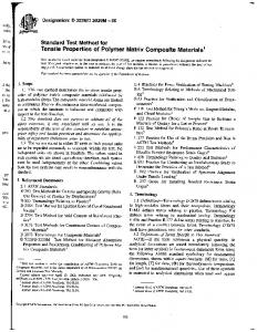
The microstructure of the original Ti foils with different thickness is shown in Fig. 2. It can be seen that homogenous equiaxed fine grains are distributed in these Ti foils. The grain size in different foils is measured by the EBSD data, which is shown in Fig. 3. The range of the grain size and the corresponding average grain size in these foils is summarized in table 2. The average grain size is used to analyze the size effect in the next section. Meanwhile, almost no twins and subgrain boundaries can be seen in this condition. The texture components in Ti foils with different thickness in the normal direction (ND) are illustrated by inverse pole figures (IPF) which can be seen in Fig. 4. The texture intensity is determined through the diffraction intensity of XRD, which can be calculated as [37] : 𝑃𝐻𝐾𝐿 =
𝐼𝐻𝐾𝐿 𝑅 𝐼𝐻𝐾𝐿
/
𝐼𝐻𝐾𝐿 ∑𝑛 1 𝑁𝐻𝐾𝐿 𝑅 𝐼𝐻𝐾𝐿 𝑛 ∑1 𝑁𝐻𝐾𝐿
(1)
Where PHKL is the pole density of {HKL}, IHKL is the diffraction intensity of {HKL} 𝑅 of pure Ti foils, 𝐼𝐻𝐾𝐿 is the diffraction intensity of {HKL} of Pure Ti powder, NHKL
is the coordination number of {HKL}, n is the number of diffraction planes. Although the intensity of the texture is slightly different, the main texture components in the different Ti foils are similar, which are determined as (101̅3), (101̅4) and (112̅4). 3.2 The tensile property The flow stress-stain curves of the different specimens are plotted in Fig. 5. It can be seen from Fig. 5a that the tensile engineering stress-strain curves of Ti foils, apart from the foils with thickness of 10 μm and 5 μm, have an obvious yield point. The
mechanical properties of these Ti foils are shown in Table 3. The true stress and the true strain can be calculated by the formulas T ln(1 ) and T (1 ) , where T is true strain, and T is true stress. The true stress-true strain curves are demonstrated in Fig. 5b. Fig. 6 shows the relationship between the mechanical properties and the thickness. It can be clearly seen that the yield strength and the tensile strength remain stable when the thickness is larger than 50 μm. The strength declines when the thickness decreases from 50 μm to 30 μm, and the strength increases when the thickness varies from 30 μm to 5 μm, as shown in Fig. 6a and Table 3. In addition, the elongation of the Ti foils with the thickness of 200 μm is the maximum value, which is about 41.3%. The elongation decreases with the decreasing in the thickness, and the elongation of Ti foils with the thickness of 5 μm reaches a minimum value, which is about 4.6%. The work-hardening behavior is conveniently characterized by the dependence of the work-hardening rate on the flow stress [38-40]. The work-hardening rate can be obtained by the formula d / d [38-40]. Fig. 7 shows the work-hardening behavior of Ti foils with different thickness. It can be found that the work-hardening rate of Ti foils decreases with increasing true stress. The work-hardening rate of Ti foils with the thickness above 50 μm has the similar variation trends, which is higher than that of Ti foils with the thickness of 30 μm and 20 μm. Meanwhile, Ti foils with the thicknesses of 10 μm and 5 μm have higher work hardening rate than that of Ti foils with the thickness of 30 μm and 20 μm. To sum up, Ti foils with the thickness of 30 μm and 20 μm have the lowest work hardening rate among all the foils.
3.3 The microstructure after tensile deformation Fig. 8 shows the macro-fracture surface of Ti foils after tensile testing. It can be found that the fracture mode changes from a shear fracture to normal fracture when the thickness is below 20 μm. The shear fracture usually inclines at an angle of 50 ~ 60 degree with respect to the tensile direction. Fig. 9 shows the SEM fracture morphologies of Ti foils with different thickness. Just as the macro-fracture, the micro-fracture also changes when the thickness is below 20 μm. When the thickness is larger than 20 μm, a large number of dimples can be observed on the fracture surface. However, dimples do not appear on the fracture surface with the thickness less than 20 μm. Tearing edges, slip traces and slipping steps can be observed in Fig. 9f. The change of the fracture mode also indicates the decreasing of elongation. The microstructure close to the fracture was also investigated by EBSD. Compared with the original EBSD microstructure in Fig. 2, the image quality (IQ) becomes much lower, which is due to the deformation microstructure including dislocation boundaries and deformation twins, as shown in Fig. 10. Meanwhile, the types of the twins are determined, which are the {10 1̅2 } extension twins and {112̅2} contraction twins, as indicated by blue lines and red lines respectively. It is noteworthy that the density of twins decreases as the thickness decreases, as shown in table 4. Fig. 11 shows the typical TEM micrographs of the different deformation microstructure in Ti foils. It can be seen that besides twins, dislocation cells, and
needle-shaped fcc-Ti are also developed. However, the dominate deformation microstructures are different in different thickness. For the foils with a thickness of 200 μm, a lot of twins and a few of cased of the fcc-Ti phase can be observed. The width of the fcc-Ti is usually about 20 nm, as shown in Fig. 11b and c. Meanwhile, it can be found that the fcc-Ti is always nucleated on the dislocation boundaries. More precisely, the interface of the fcc-Ti lies on dislocations, as shown in Fig. 11c. It can be inferred that the nucleation of fcc-Ti is related with the dislocations. As the thickness decreases, the density of fcc-Ti increases. As the fcc-Ti grows larger and two groups of fcc-Ti can be obtained, as shown in Fig. 12, which are indicated by yellow arrows and red arrows, respectively. When viewed along the [0001]hcp crystal zone axis, they are form an inclination angle of 60°. It can also be seen that a group of the fcc-phase can meet the same g · b = 0 invisibility criterion as one group of dislocations in hcp-matrix. It is further proved that the development of fcc-phases is closely related with dislocations. The microstructure of these phases is also investigated by HRTEM, as shown in Fig. 13. It can be determined that the orientation relationship between hcp-Ti and the fcc-Ti is hcp // fcc, {2̅110}HCP // {1̅10}fcc and {011̅0}hcp // {110}fcc. The transition matrix B is an important tool and can be used to calculate or predict crystal planes and crystal direction of new phases under the given zone axis of the matrix. According to the orientation relationships of the two phases, three sets of parallel crystal planes can be obtained as: (H1 K1 L1)fcc // (h1k1 l1)hcp =(220)fcc // (010)hcp
(H2 K2L2)fcc // (h2k2 l2)hcp = (2̅20)fcc // (2̅10)hcp
(2)
(H3 K3 L3)fcc // (h3k3 l3)hcp =(001)fcc // (001)hcp Then, the transition matrix B between the [UVW]fcc and [uwv]hcp direction can be described as follows: [ ]=
[ ]
(3) 1 1
=[
]
0 0
0
0 [
[0 0
]
(4)
]
where Di and di (i = 1, 2, 3) are the interplanar spacing of (Hi Ki Li)fcc and (hi ki li) hcp, respectively. In our study, d1/D1 = d(010)hcp/d(220)fcc = 1.68 d2/D2 = d(2̅10)hcp/d(2̅20)fcc = 1
(5)
d3/D3 = d(001)hcp/d(001)fcc = 1.09 Then, the transition B can be obtained as: 0 0 =[ 0 0 0
01 0 0
0 0] 10
(6)
Therefore, the direction [UVW]fcc of the fcc phase, which is parallel to a given direction [uvw]hcp of hcp matrix, can be calculated by the transition matrix B. Furthermore, it can be seen from Fig 13 that stacking faults are developed at the interface of the fcc-Ti and the hcp-matrix. The presence of streaking in the corresponding Fast Fourier Transformation (FFT) patterns indicated by the red arrow
indicates that the stacking faults are on the (1̅100) basal planes. The stacking faults are concentrated on the growing end of fcc-phase, as shown in Fig. 14. Many fine fcc-bands between stacking faults are developed at the growing end of the fcc-phase. Therefore, it can be inferred that the formation of the fcc-Ti is related with appearance of the stacking faults. Stacking faults are closely related to partial or incomplete dislocations in crystals. Different from full or complete dislocations, the glide of partial dislocations changes the local structure of the crystal. It has been found that the phase transformation from the hcp-matrix to the fcc-Ti is induced by dislocation gliding on {101̅0} of multiple Shockley partial dislocations with a Burgers vector of b=a/6 [33]. The stacking faults and partial dislocations are also analyzed by geometric phase analysis (GPA, shown in Fig.14). In order to show the partial dislocations and stacking faults clearly, the inverse Fast Fourier Transformation (IFTT) images in Figs. 14d and f are obtained by selecting the spots of (112̅0) and (101̅0), respectively. Strain component in Figs. 14c and e is parallel to the direction of and , respectively. It can be found that the strain fields in the direction is much weaker than that in the direction, which is consistent with the calculated strain mismatch. The long extending strain field along the (101̅0) also indicates that stacking faults are developed in on the (101̅0), and about 5% strain is produced at the interface. Therefore, the formation of the fcc phase can act as another type of plastic deformation mode comparable to compression twins [33-34, 36]. When the thickness is below 20 μm, the dominate deformation microstructure is dislocation cells. Some nano-twins can also be seen, as shown in Fig. 11i. However,
few of the fcc-Ti is present at this condition. It seems that the main deformation mechanism is dislocation slipping at this condition. 4. Discussions 4.1 The constitutive equations based on size effects The Ti foils show different properties and deformation microstructure at different thickness. It means that the mechanical property of Ti foils is influenced by the “size effect”. In order to understand the size effect on the mechanical properties, it is necessary to establish a constitutive relation to describe the relationship between stress and strain. The Hollomon model is used to analyze the true stress-strain curves and the equation is as follows: true = Ktr
e
𝑛
(7)
Where true is the true stress, true is the true strain, K is the strength coefficient, and n is the work-hardening exponent. According to the experimental results, the Hollomon model parameters can be obtained by a nonlinear least squares fitter (NLSF) of MATLAB, as shown in Table 5. Based on the above analysis, the studied foils can be divided into two groups. One group is between 200 μm and 50 μm, and the other group is between 30μm and 5 μm thick. When the thickness is above 50 μm, the effect of thickness on the mechanical properties of Ti foils is very small. Therefore, only the grain size is considered. Combining the Hollomon equation and the Hall-Petch relation, the Eq. (8) is established. The experimental data of foils with thicknesses between 200 μm and 50 μm is used to calculate the coefficient values of k1 and k2 in the Eq. (8).
f ( , d ) (k1 k 2
1 d
) n
(8)
k1 0.4817k 2 724 k1 0.5634k 2 785
(9)
k1 and k2 is calculated to be 364.346 and 746.634. Then, the constitutive model of Ti foils above 50 μm can be written as:
f ( , d ) (364.346 746.634
1
) n
d
(10)
As shown in Fig. 15b, it can be found that the calculated results are in good agreement with the experiment results. When the thickness is below 30 μm, both the effects of thickness and grain size need to be considered. Therefore, the ratio t/d (thickness/average grain size) is used, as shown in the Eq. (11). According to the experimental data of the foils with thickness between 30 μm and 5 μm, the Eq. (12) can be obtained.
t d
f ( , t / d ) F (t / d ) n (a b t / d c( ) 1 ) n a 3.0336b 0.1087c 627 a 1.8474b 0.293c 624 a 1.4058b 0.506c 598
(11)
(12)
Therefore, a constitutive model is established as:
t d
F (t / d ) n (719.287 24.247 t / d 172.335( ) 1 ) n
(13)
It can be also seen that the constitutive equation agrees well with the results of experiments, as shown in Fig. 15c. It can be concluded that the parameter of the ratio t/d plays an important role in the mechanical behaviors of the studied Ti foils. When the t/d is larger than 10, the surface has little influence on the mechanical properties. Only the grain size should be
considered in this condition. When the t/d is lower than 10, the grains on the surface account for a large part of the samples. Therefore, the surface needs be considered. 4.2 The size effect on deformation mechanisms It is found from Figs. 10 and 11 that dislocations, twins and fcc-Ti are developed during tensile deformation. The density of the twins in foils with a thickness of 200 μm is much larger than that in foils with a thickness of 5 μm. Meanwhile, the typical deformation microstructure in foils with a thickness of 5 μm is dislocation cells and some fine twins. It can be inferred that these twins in foils with a thickness of 5 μm do not have enough strain to grow when compared to foils at larger elongation. As reported, there are mainly 5 types of twins in the deformation of pure Ti [42]. The types of twins can be determined by the EBSD data, as shown in Fig. 16. It is seen that there are mainly two types of twins in the deformation of Ti foils. The red lines in Fig. 16c and f show twins boundaries with a rotation angle of 65° around a axis, which can be identified as the {112̅2} type compression twins. The blue lines in Fig. 16c and f represent twins boundaries with a rotation angle of 85° around a axis, which can be identified as of the {101̅2} type tensile twins. This result is consistent with the previous investigations, which reported that the {101̅2} extension twins and the {112̅2} contraction twins are the most activate twins induced by deformation at ambient temperature [43-45]. Furthermore, the twin fraction in the used Ti foils at different thickness is shown in Table 4. The density of deformation twins decreases as the thickness decreases. It can be inferred that the density of deformation twinning strongly depends on the sample
size, which is one of the two effects on deformation twinning in hcp materials [46]. For Ti, the stress required for activating twinning increases drastically with the decrease of the sample size, following a Hall-Petch type relationship where the exponent was close to 1 [47-49]. The simulation results show that the fcc-phase can be nucleated at a tension strain above 4% and does reach its maximum volume fraction of approximately 27% at a strain of 17.5% [50]. It may be concluded that the volume fraction of the fcc-Ti with thickness of 20 μm and 30 μm is higher than that in the other foils, since the strain of these foils is close to 17.5%. Meanwhile, it can be found from the TEM micrographs that the density and the size of the fcc-Ti are largest at this condition. Fig. 7 shows the foils with thickness of 20 μm and 30 μm have the lowest work-hardening rate. It can be inferred that the hardening effect of the fcc-Ti is lower than that of twins. The hardening effect of the fcc-phase result from the interface. As shown in Fig. 14, the interface is a kind of semi-coherent interface with some dislocations, which causes about 5% strain. Meanwhile, the interface lies on the slip planes of prism planes of {1100}, which can block the dislocation slipping on these planes. Although the hardening effect of fcc-phase has been discussed in some previous results, it is hard to determine the strengthening effect quantitatively [33-35]. Meanwhile, this can also be deduced from the interface formation energy of the fcc-Ti is much lower than that of coherent twin boundaries, such as {101̅2} and {112̅2} twins [34]. Furthermore, it has been found that slip occurs most easily via the activation of dislocations with 1/3a type Burgers vector primarily on prism planes of {1100} in pure Ti [42-45].
The Burgers vector of 1/3a type is similar to that of 1/2{110} type dislocations in the fcc-Ti, as shown in Fig. 14c and d. Since the interface of the fcc-phase and the hcp-matrix lies on the prismatic planes of the hcp-matrix and {110} planes of the fcc-Ti, the dislocations can easily cross slip from the hcp-matrix to the fcc-Ti. It may be inferred that the inhibition effect of dislocation slipping is not so high. When the thickness ranges from 5 to 10 μm, the main deformation microstructure is dislocation cells. In this case, the surface of the Ti foils is covered by an oxide layer, which can be confirmed in Fig. 17. The volume fraction of the oxide layer on the surface increases with decreasing the thickness of the samples. The oxide layer has a strong influence on the mechanical behavior and should therefore be taken into account. The oxide layer can increase the tensile strength of thin foils because the dislocations have to pile up before the sample can deform plastically [25]. The effect of the oxide layer at the surface has already been found in the aluminum foils [25]. It seems that the length of the pileup of dislocations is limited by the thickness of the specimen. Meanwhile, the deformation becomes more non-homogeneous. Therefore, the elongation decreases at this situation.
Conclusion In order to show the size effects on the mechanical behaviors and deformation mechanisms of commercial pure Ti foils with thickness ranging from 5 μm to 200 μm, the tensile properties and deformation microstructure have been systematically
studied. (1) The mechanical properties of Ti foils are influenced by the size effect. The strength changes little when the thickness ranges from 200 μm to 50 μm while the strength decreases with the decrease in thickness when the thickness is between 50 μm and 30 μm. However, the strength increases with the decrease of thickness when the thickness is below 30 μm. In addition, the elongation always decreases as the thickness decreases. (2) When the thickness is above 50 μm, only the grain size d should be considered. When the thickness is below 30 μm, the ratio of the thickness t to the grain size d is less than 10. In this condition, the ratio t/d needs to be considered. Two kinds of the constitutive equations are established as follows:
f ( , d ) (364.346 746.634
1
) n
t >30μm
d t d
F (t / d ) n (719.287 24.247 t / d 172.335( ) 1 ) n
t ≤ 30μm
(3) When the thickness is above 20 μm, a large number of dimples can be observed on the fracture surfaces. For the thickness below 20 μm, only tearing edges and slip traces can be seen on the fracture surfaces. (4) The plastic deformation mechanism of Ti foils includes dislocation slipping and twinning, and the phase transformation of the hcp-Ti to the fcc-Ti. The volume of deformation twins decreases as the thickness decreases. The fcc-phase has a larger volume fraction when the thickness is 20 μm and 30 μm. However, here a smaller hardening effect than that of twins is observed. The deformation microstructure of the foils with the thickness of 5 μm and 10 μm is mainly dislocation cells. The strength is
improved because of the oxide layer on the surface.
ACKNOWLEDGMENTS This work is supported by National Natural Science Foundation of China (51704091 and 51701056), China Postdoctoral Science Foundation (2016M602002) and the Fundamental Research Funds for the Central Universities (JZ2018HGTB0262 and PA2018GDQT0018), the 111 Project (B18018), the CSC scholarship (201706695008), and Anhui Natural Science Foundation (1608085QE95 and 1708085QE94).
References [1] T.A. Kals, R. Eckstein, Miniaturization in sheet metal working, J. Mater. Process. Technol. 103 (2000) 95-101. [2] M. Geiger, M. Kleiner, R. Eckstein, N. Tiesler, U. Engel, Microforming, CIRP Ann-Manuf Technol 50 (2001) 445-462. [3] U. Engel, R. Eckstein, Micro–forming from basic research to its real realization, J. Mater. Process. Technol. 103 (2002) 35-44. [4] M. Geiger, F. Vollertsen, R. Kals, Fundamentals on the Manufacturing of Sheet Metal Microparts, CIRP Ann-Manuf Technol 45 (1996) 277-282. [5] F. Vollertsen, Z. Hu, H.S. Niehoff, C. Theiler, State of the art in micro forming and investigations into micro deepdrawing, J. Mater. Process. Technol. 151 (2004) 70-79. [6] J.T. Gau, C. Principe, J.W. Wang, An experimental study on size effects on flow stress and formability of aluminum and brass for microforming, J. Mater. Process.
Technol. 184 (2007) 42-46. [7] W.L. Chan, M.W. Fu, B. Yang, Study of size effect in micro-extrusion process of pure copper, Mater. Des. 32 (2011) 3772-3782. [8] L.V. Raulea, A.M. Goijaerts, L.E. Govaert, F.P.T. Baaijens, Size effects in the processing of thin metal sheets, J. Mater. Process. Technol. 115 (2001) 44-48. [9] F.H. Yeh, C.L. Li, Y.H. Lu, Study of thickness and grain size effects on material behavior in micro-forming, J. Mater. Process. Technol. 201 (2008) 237-241. [10] W.L. Chan, M.W. Fu, J. Lu, J.G. Liu, Modeling of grain size effect on micro deformation behavior in micro-forming of pure copper, Mat. Sci. Eng. A 527 (2010) 6638-6648. [11] W.L. Chan, M.W. Fu, J. Lu, The size effect on micro deformation behaviour in micro-scale plastic deformation, Mater. Des. 32 (2011) 198-206. [12] J.H. Deng, M.W. Fu, W.L. Chan, Size effect on material surface deformation behavior in micro-forming process, Mat. Sci. Eng. A 528 (2011) 4799-4806. [13] L. Peng, X. Lai, H.J. Lee, J. Ni, Analysis of micro/mesoscale sheet forming process with uniform size dependent material constitutive model, Mat. Sci. Eng. A 526 (2009) 93-99. [14] X. Lai, L. Peng, P. Hu, S. Lan, J. Ni, Material behavior modelling in micro/meso-scale forming process with considering size/scale effects, Comput. Mater. Sci. 43 (2008) 1003-1009. [15] L. Peng, F. Liu, J. Ni, X. Lai, Size effects in thin sheet metal forming and its elastic-plastic constitutive model. Mater. Des. 28 (2007) 1731-1736.
[16] M.W. Fu, W.L. Chan, Geometry and grain size effects on the fracture behavior of sheet metal in micro-scale plastic deformation, Mater. Des. 32 (2011) 4738-4746. [17] C.J. Wang, D.B. Shan, J. Zhou, B. Guo, L.N. Sun, Size effects of the cavity dimension on the microforming ability during coining process, J. Mater. Process. Technol. 187 (2007) 256-259. [18] Y.H. Zhao, Y.Z. Guo, Q. Wei, A.M. Dangelewiez, C. Xu, Y.T. Zhu, T.G. Langdon, Y.Z. Zhou, E.J. Lavernia, Influence of specimen dimensions on the tensile behavior of ultrafine-grained Cu, Scripta Mater. 59 (2008) 627-630. [19] Y.H. Zhao, Y.Z. Guo, Q. Wei, T.D. Topping, A.M. Dangelewicz, T.G. Langdon, Y.Z. Zhou, E.J. Lavernia, Influence of specimen dimensions and strain measurement methods on tensile stress–strain curves, Mat. Sci. Eng. A 525 (2009) 68-77. [20] J.Q. Ran, M.W. Fu, W.L. Chan, The influence of size effect on the ductile fracture in micro-scaled plastic deformation, Int. J. Plasticity 41 (2013) 65-81. [21] J.F. Michel, P. Picart, Size effects on the constitutive behaviour for brass in sheet metal forming, J. Mater. Process. Technol. 141 (2003) 439-446. [22] W.L. Chan, M.W. Fu, Studies of the interactive effect of specimen and grain sizes on the plastic deformation behavior in microforming, Int. J. Adv. Manuf. Technol. 62 (2012) 989-1000. [23] W.L. Chan, M.W. Fu, Experimental studies and numerical modeling of the specimen and grain size effects on the flow stress of sheet metal in microforming, Mat. Sci. Eng. A 528 (2011) 7674-7683. [24] Y. Wang, P.L. Dong, Z.Y. Xu, H. Yan, J.P. Wu, J.J. Wu, A constitutive model for
thin sheet metal in micro-forming considering first order size effects, Mater. Des. 31 (2010) 1010-1014. [25] M. Lederer, V. Gröger, G. Khatibi, B. Weiss, Size dependency of mechanical properties of high purity aluminium foils, Mat. Sci. Eng. A 527 (2010) 590-599. [26] C. Leyens, M. Peters, Titanium and Titanium Alloys: Fundamentals and Applications, Springer-Verlag, 2003, pp. 321-334. [27] C.N. Elias, J.H.C. Lima, R. Valiev, M.A. Meyers, Biomedical applications of titanium and its alloys, JOM 60 (2008) 46-49. [28] M. Geetha, A.K. Singh, R. Asokamani, A.K. Gogia, Ti based biomaterials, the ultimate choice for orthopaedic implants-A review, Prog. Mater. Sci. 54 (2009) 397-425. [29] D.R. Chichili, K.T. Ramesh, K.J. Hemker, Adiabatic shear localization in α-titanium: experiments, modeling and microstructural evolution, J. Mech. Phys. Solids. 52 (2004) 1889-1909. [30] W.G. Guo, J.Y. Cheng, Mechanical properties and deformation mechanisms of a commercially pure titanium, Acta Mater 47 (1999) 3705-3720. [31] S. Farenc, D. Caillard, An in situ study of prismatic glide in α titanium at low temperatures, Acta Metall. Materialia 41 (1993) 2701-2709. [32] M.G. Glavicic, A.A. Salem, S.L. Semiatin, X-ray line-broadening analysis of deformation mechanisms during rolling of commercial-purity titanium, Acta Mater 52 (2004) 647-655. [33] D.H. Hong, T.W. Lee, S.H. Lim, W.Y. Kim, S.K. Hwang, Stress-induced
hexagonal
close-packed
to
face-centered
cubic
phase
transformation
in
commercial-purity titanium under cryogenic plane-strain compression, Scr. Mater. 69 (2013) 405-408. [34] H.C. Wu, A. Kumar, J. Wang, X.F. Bi, C.N. Tomé, Z. Zhang, S.X. Mao, Rolling-induced Face Centered Cubic Titanium in Hexagonal Close Packed Titanium at Room Temperature, Sci. Rep. 6 (2016) 24370. [35] Q. Yu, J. Kacher, C. Gammer, R. Traylor, A. Samanta, Z. Yang, A. M. Minor, In situ TEM observation of FCC Ti formation at elevated temperatures, Scr. Mater. 140 (2017) 9-12. [36] L. Niu, S. Wang, C. Chen, S.F. Qian, R. Liu, H. Li, B. Liao, Z.H. Zhong, P. Lu, M.P. Wang, P. Li, Y.C. Wu, L.F. Cao, Mechanical behavior and deformation mechanism of commercial pure titanium foils, Mat. Sci. Eng. A 707 (2017) 435-442. [37] K. L. Murty, I. Charit, Texture development and anisotropic deformation of zircaloys, Progress in Nuclear Energy 48 (2006) 325-359. [38] U.F. Kocks, H. Mecking, Physics and phenomenology of strain hardening: the FCC case, Prog. Mater. Sci. 48 (2003) 171-273. [39] H. Becker, W. Pantleon, Work-hardening stages and deformation mechanism maps during tensile deformation of commercially pure titanium, Comput. Mater. Sci. 76 (2013) 52-59. [40] T. Hama, H. Nagao, A. Kobuki, H. Fujimoto, H. Takuda, Work-hardening and twinning behaviors in a commercially pure titanium sheet under various loading paths, Mat. Sci. Eng. A 620 (2015) 390-398.
[41] H.D. Fan, Z.H. Li, M.S. Huang, X. Zhang, Thickness effects in polycrystalline thin films: Surface constraint versus interior constraint, Int. J. Solids. Struct. 48 (2011) 1754-1766. [42] Y. Zhong, F. Yin, K. Nagai, Role of deformation twin on texture evolution in cold-rolled commercial-purity Ti, J. Mater. Res. 23 (2008) 2954-2966. [43] T. Wang, B. Li, M. Li, Y. Li, Z. Wang, Z. Nie, Effects of strain rates on deformation twinning behavior in α-titanium, Mater. Charact. 106 (2015) 218-225. [44] Y.B. Chun, S.H. Yu, S.L. Semiatin, S.K. Hwang, Effect of deformation twinning on microstructure and texture evolution during cold rolling of CP-titanium, Mat. Sci. Eng. A 398 (2005) 209-219. [45] X.G. Deng, S.X. Hui, W.J. Ye, X.Y. Song, Analysis of twinning behavior of pure Ti compressed at different strain rates by Schmid factor, Mat. Sci. Eng. A 575 (2013) 15-20. [46] Q. Yu, R.K. Mishra, A.M. Minor, The Effect of Size on the Deformation Twinning Behavior in Hexagonal Close-Packed Ti and Mg, JOM 64 (2012) 1235-1240. [47] Q. Yu, Z.W. Shan, J. Li, X. Huang, L. Xiao, J. Sun, E. Ma, Strong crystal size effect on deformation twinning, Nature 463 (2010) 335-338. [48] X. L. Nan, H.Y. Wang, Z.Q. Wu, E.S. Xue, L. Zhang, Q.C. Jiang, Effect of c/a, axial ratio on Schmid factors in hexagonal close-packed metals, Scr. Mater. 68 (2013) 530-533. [49] L. Chang, C.Y. Zhou, X.M. Pan, X.H. He, Size-dependent deformation
mechanism transition in titanium nanowires under high strain rate tension, Mater. Des. 134 (2017) 320-330. [50] J.Q. Ren, Q.Y. Sun, L. X, X.D. Ding, J. Sun, Phase transformation behavior in titanium single-crystal nanopillars under [0001] orientation tension: A molecular dynamics simulation, Comput. Mater. Sci. 92 (2014) 8-12.
Fig. 1. Dimensions of the tensile testing specimens (unit: mm). Fig. 2. EBSD microstructure of the original Ti foils with different thicknesses. (a) t = 200 μm, (b) t = 100 μm, (c) t = 80 μm, (d) t = 50 μm, (e) t = 30 μm, (f) t = 20 μm, (g) t = 10 μm, (h) t = 5 μm. The black lines show grain boundaries. Fig. 3. Grain size distributions of original Ti foils. (a) t = 200 μm, d = 4.31 μm, (b) t = 100 μm, d = 3.68 μm, (c) t = 80 μm, d = 3.15 μm, (d) t = 50 μm, d = 4.04 μm, (e) t = 30 μm, d = 3.26 μm, (f) t = 20 μm, d = 3.55 μm, (g) t = 10 μm, d = 2.93 μm, (h) t = 5 μm, d = 2.53μm. Fig. 4. Inverse pole figure maps of original Ti foils with different thickness in the normal direction (ND). (a) t = 200 μm, (b) t = 100 μm, (c) t = 80 μm, (d) t = 50 μm, (e) t = 30 μm, (f) t = 20 μm, (g) t = 10 μm, (h) t = 5 μm. Fig. 5. The engineering stress-strain curves (a), and the true stress-strain curves (b) of Ti foils with different thicknesses. Fig. 6. The variations of the tensile mechanical behavior with specimen thickness. (a) Yield strength and tensile strength, (b) Fracture elongation. Fig. 7. Work-hardening behavior of commercially pure titanium foils with different thickness. Fig. 8. The macro-fracture morphologies of Ti foils with different thickness. (a) t = 200 μm, (b) t = 100 μm, (c) t = 80 μm, (d) t = 50 μm, (e) t = 30 μm, (f) t = 20 μm, (g) t = 10 μm, (h) t = 5 μm. Fig. 9. SEM images show the fracture surface of Ti foils with different thickness. (a) t = 200 μm, (b) t = 100 μm, (c) t = 80 μm, (d) t = 50 μm, (e) t = 30 μm, (f) t = 20 μm, the inserted image showing the slip traces and slip steps. (g) t = 10 μm, (h) t = 5 μm. Fig. 10. EBSD microstructure of Ti foils with different thicknesses after tensile deformation. (a) t = 200 μm, (b) t = 100 μm, (c) t = 80 μm, (d) t = 50 μm, (e) t = 30 μm, (f) t = 20 μm, (g) t = 10 μm, (h) t = 5 μm. The inserting enlarged image quality maps show twins, where red boundaries show {112̅2} twin boundaries and blue boundaries show {101̅2} twin boundaries. Fig. 11. The typical deformation microstructure in Ti foils with different thickness. (a) Twins, (b), and (c) Fcc-Ti in Ti foils with a thickness of 150 μm. (d) Twins and (e) Fcc-Ti in Ti foils with a thickness of 30 μm. (f) Fcc-Ti in Ti foils with a thickness of 20 μm. (g) Dislocations in Ti foils with a thickness of 10 μm. (h) Dislocations and (i)
Twins in Ti foils with a thickness of 5 μm. The yellow arrows show Fcc-Ti phase, the red arrows show twins and the green arrows show dislocation boundaries. Fig. 12. (a) Bright-field TEM images showing two groups of FCC-Ti phases indicated by yellow and red arrows, (b) the corresponding SADPs. The same region in Fig. (a) under different operation vector (c) g=(1̅100), (d)g=(011̅0). Fig. 13. HRTEM micrographs showing the fcc-Ti at different zone axis. (a) An HRTEM image and (b) the corresponding FFT pattern viewed along HCP//FCC. (c) An HRTEM image and (d) the corresponding FFT pattern viewed along HCP//FCC. The presence of streaking indicated by the red arrow indicates that the stacking faults are on the (1̅100) planes. Fig. 14. Geometric phase analysis (GPA) of the fcc-Ti. (a) HRTEM image of the fcc-Ti. Inset is the FFT of the image. (b) The corresponding IFFT image of (a), the enlarged region showing some fcc-bands at the front of fcc-Ti. (c) Strain component parallel to (112̅0) obtained by GPA and the corresponding IFFT image (d). (e) Strain component parallel to (101̅0) obtained by GPA and the corresponding IFFT image (f). Dislocations cores are denoted by the symbols. Fig. 15. The flow stress curves of the experimental results and the calculated results based on the proposed models. (a) The experimental data, (b) The experimental data and the results calculated by Eq. (10) for Ti foils between 200 μm and 50 μm, (c) The experimental data and the results calculated by Eq. (13) for Ti foils between 30 μm and 5 μm. Fig. 16. EBSD microstructure of the Ti foils with thickness of 200 μm (a, b, and c) and 5μm (d, e, and f). (a, d) The IQ maps, (b, e) the orientation maps, high angle boundaries (>15°) are indicated by thick black lines, and low angle boundaries (1° ~ 15°) are indicated by thin black lines. (c, f) The construction maps of twins, blue lines show {101̅2} extension twins and red lines show {112̅2} contraction twins. Fig. 17. The XRD pattern and HRTEM micrographs showing the TiO2 in the Ti foils with a thickness of 5 μm. (a) XRD pattern. (b) The HRTEM micrograph, (c) and (d) show the corresponding FFT in region A and B. The hcp-Ti is in the zone axis of .
R60
15
20
60
50 190
Fig. 1.
a
c
b
d
20 μm
20 μm
20 μm
e
20 μm
f
20 μm
20 μm
h
g
RD TD
20 μm
Fig. 2.
20 μm
0.30
0.35
a
b 0.30
t =100m
t =200m
0.20
d =3.68m
0.25
d =4.31m
Area fraction (%)
Area fraction (%)
0.25
0.15
0.10
0.05
0.20 0.15 0.10 0.05
0.00
0.00
2
3
4
5
6
7
8
9
1
2
3
4
Grain size (m)
5
6
7
8
Grain size (m) 0.30
d
c
0.30
0.25
t =80m
t =50m
d =3.15m
d =4.04m Area fraction (%)
Area fraction (%)
0.25
0.20
0.15
0.10
0.20
0.15
0.10
0.05
0.05
0.00
0.00 1
2
3
4
5
6
7
1
8
2
3
4
5
6
7
8
9
10
11
Grain size (m)
Grain size (m) 0.30
e t =30m
t =20m
0.25
d =3.26m
d =3.55m
0.20
Area fraction (%)
Area fraction (%)
f
0.30
0.25
0.15
0.10
0.05
0.20
0.15
0.10
0.05
0.00 1
2
3
4
5
6
0.00
7
1
Grain size (m)
2
3
4
5
6
0.35
8
9
0.35
g
h
0.30
0.30
t =5m
t =10m 0.25
d =2.53m
0.25
d =2.93m Area fraction (%)
Area fraction (%)
7
Grain size (m)
0.20 0.15 0.10 0.05
0.20 0.15 0.10 0.05
0.00
0.00 0
Fig. 3.
1
2
3
4
5
Grain size (m)
6
7
8
0
1
2
3
4
Grain size (m)
5
6
7
a
c
b
d
f
e
g
Fig. 4.
h
700
500
a
b 600 500
200103nm 100103nm 80103nm 50103nm 30103nm 20103nm 10103nm 5103nm
300
200
100
0 0.0
0.1
0.2
0.3
True stress (MPa)
Stress (MPa)
400
200103nm 100103nm 80103nm 50103nm 30103nm 20103nm 10103nm 5103nm
400 300 200 100 0 0.00
0.4
0.05
0.10
0.15
0.20
0.25
0.30
0.35
True strain
Strain
Fig. 5. 550 500
b
50
450
40
400
30
Elongation (%)
Stress (MPa)
60
Yield strength Tensile strength
a
350 300
20 10 0
250
-10
200 0
50
100
150
-20
200
0
20
40
Sample thickness (m)
Work-hardening rate (MPa)
4000
200103nm 100103nm 80103nm 50103nm 30103nm 20103nm 10103nm 5103nm
3000
2000
1000
0 300
350
400
450
500
True stress (MPa)
Fig. 7.
80
100
120
140
Sample thickness (m)
Fig. 6.
250
60
550
600
650
160
180
200
a 61° b
c
60°
56° 64°
54°
d 57° e 54°
f
g
h
Fig. 8.
a
b
Dimples Dimples 30 μm
30 μm
c
d
Dimples Dimples 30 μm
e
f
1 μm
Dimples Slip traces Tearing edge 10 μm
h
g
Slip traces
Slip traces
5 μm
Fig. 9. .
5 μm
a
c
b
20 μm e
e
20 μm g
20 μm
20 μm f
20 μm
20 μm
h
RD TD
20 μm
Fig. 10.
20 μm
a
c
b
Dislocation Dislocation boundaries
Twins
Fcc-Ti Fcc-Ti
d
e
Dislocation boundaries
f
Twins Fcc-Ti Fcc-Ti
g
i
h
Dislocation cells
Dislocation cells Twins
Fig. 11.
a
b
(220)
(200)
(200) (220)
[001]FCC
c
Fig. 12.
d
[001]FCC
a
b (220)
fcc (200) (220)
(200)
fcc fcc
[001]FCC
[001]FCC
d
c
(311) (220) (1𝟏𝟏)
fcc
[1𝟏𝟐]FCC
Fig. 13.
a
b
(220) (200) (020) 2 nm
5 nm
c
d
-0.05
0.05
e
f
Stacking faults
-0.05
Fig. 14.
0.05
a
600
200m 100m 80m 50m 30m 20m 10m 5m
True stress (MPa)
500
400
300
200
100 0.00
0.05
0.10
0.15
0.20
0.25
0.30
0.35
0.40
True strain 650
b
450
550 500 450
Experiment Proposed model(Eq.(10)) 200m 100m 80m 50m
400 350
True stress (MPa)
True stress (MPa)
600
c
400
350
Experiment Proposed model(Eq.(13)) 30m 20m 10m 5m
300
250
300 0.00
0.05
0.10
0.15
0.20
0.25
True strain
Fig. 15.
0.30
0.35
0.40
200 0.00
0.05
0.10
True strain
0.15
0.20
a
b
c
d
20μm e
f
RD
20μm Fig. 16.
TD
1000
5m
Ti TiO2
800
d
b
a
Intensity (a.u.)
600
400
200
c
0 20
40
60
80
100
120
140
2/Degree
Fig. 17. Table 1. Chemical compositions of Ti foil (wt.%). C
O
N
H
Fe
Al
Ti
0.02114
0.14
0.21
0.0080
0.049
1.61
97.96186
Table 2. The grain size of Ti foils with different thickness. Thickness t (m) 200 100 80 50 30 20 10 5
The grain size range (m)
2.7 ~ 5.5 2.4 ~ 4.5 1.7 ~ 4.5 2.0 ~ 6.0 1.6 ~ 4.6 1.8 ~ 5.0 1.6 ~ 4.0 1.4 ~ 3.5
The mean grain size d (m) 4.31 3.68 3.15 4.04 3.26 3.55 2.93 2.53
Table 3. Mechanical properties of Ti foils with different thickness Thickness of Ti foil (m)
Yield (MPa)
200 100 80 50 30 20 10 5
strength
Tensile strength (MPa)
332±1.4 338±2.7 350±17.6 348±8.0 236±5.4 264±8.5 286±1.3 330±3.4
Yield ratio (%)
451±3.4 456±2.3 479±18.6 450±7.7 360±4.4 359±7.5 378±1.8 385±23.0
Fracture elongation (%)
73.6 74.1 73.1 77.3 65.6 73.5 75.7 85.7
41.3±1.3 29.2±3.0 34.6±3.6 22.3±3.2 21.1±6.7 16.5±3.8 8.5±0.3 4.6±1.8
Table 4. The twin fraction determined by EBSD in Ti foils with different thickness Thickness / μm
200
100
80
50
30
20
10
5
{112̅2}/%
1.86
0.71
0.12
0.18
0.13
0.62
0.68
0.50
{101̅2}/%
9.49
7.29
6.11
5.51
1.71
0.40
0.44
0.36
Total
11.35
8.0
6.23
5.69
1.84
1.02
1.12
0.86
Table 5. The different parameters of the Hollomon model. Thickness t (m)
t/d
K (MPa)
n
200 100 80 50 30 20 10 5
46.4 27.2 25.4 12.4 9.2 5.6 3.4 2.0
724 737 785 724 627 584 624 598
0.1687 0.1793 0.1908 0.1724 0.2152 0.1913 0.1679 0.1293