Turbo Codes [1] and Low-Density Parity-Check (LDPC). Codes [2], both iteratively ... In the LLR-domain version of BP, each check node j performs the following ...
Soft-Bit Decoding of Regular Low-Density Parity-Check Codes Sheryl L. Howard, Vincent C. Gaudet, and Christian Schlegel High Capacity Digital Communications (HCDC) Laboratory Department of Electrical and Computer Engineering ECERF Building, University of Alberta, Edmonton, Alberta T6G 2V4 {sheryl,vgaudet,schlegel}@ece.ualberta.ca
Abstract— A novel representation, using soft-bit messages, of the belief propagation decoding (BP) algorithm for lowdensity parity-check codes is derived as an alternative to loglikelihood-ratio-(LLR)-based BP and min-sum decoding algorithms. A simple approximation is also presented. Simulation results demonstrate the functionality of the soft-bit decoding algorithm. Floating point soft-bit and LLR BP decoding show equivalent performance; the approximation incurs 0.5 dB loss, comparable to min-sum performance loss over BP. Fixed point results show similar performance to LLR BP decoding; the approximation converges to floating point results with one less bit of precision.
Keywords: Low-Density Parity-Check Codes, Iterative Decoding Algorithms, Soft Output Decoding, Belief Propagation
analog designers, soft-bit decoding offers alternative computational kernels which are well-suited to analog implementation. For digital designers, soft-bit decoding provides a quantization range compatible with the iteratively improving probability messages associated with iterative decoding algorithms. Softbit decoders can easily be interfaced with iterative cancellation receivers, where soft-bit estimates are required for iterative signal cancellation. This paper is organized as follows. Section II derives the soft-bit-domain BP algorithm. Section III discusses an approximation to the algorithm of Section II. Section IV presents simulation results, including both floating point and fixed point representations. Finally, Section V concludes this paper.
I. I NTRODUCTION Turbo Codes [1] and Low-Density Parity-Check (LDPC) Codes [2], both iteratively decoded near-capacity-performing classes of error-correcting codes, are used in a number of recent digital communications standards, including W-CDMA, CDMA2000, IEEE 802.16, 802.20, DVB-RCT and DVB S-2. Turbo codes are iteratively decoded using maximum a posteriori (MAP) decoding [3], while LDPC codes are typically iteratively decoded using belief propagation (BP) [4] or suboptimal min-sum [5] algorithms. MAP and BP decoding algorithms are soft-decision algorithms which operate in either the probability or log-likelihood ratio (LLR) domains. Min-sum algorithms also operate in the LLR domain. MAP, BP and min-sum algorithms have all been implemented in recent state-of-the-art soft-decision analog [6], [7], [8], ASIC and FPGA digital [9], [10], [11] technologies. An alternate form of the BP decoding algorithm is derived in this paper, which represents decoding messages in the hyperbolic tangent domain, rather than the LLR domain. The hyperbolic tangent domain is sometimes called the soft-bit domain, as messages have a fixed range (-1,+1). The soft-bit domain, when linearly quantized, is equivalent to finer quantization of small-valued LLR messages and coarser quantization of larger-valued LLR messages. This alternate message format provides LDPC decoder designers with another degree of freedom in implementation. For The authors wish to acknowledge the financial support of the Alberta Informatics Circle of Research Excellence (iCORE) in funding this research.
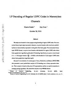
II. T HE S OFT B IT D ECODING A LGORITHM LDPC decoding is viewed graphically via a bipartite graph, or factor graph [12]. The factor graph has both variable nodes, representing the codeword bits, and parity check nodes, representing the parity check equations of the code’s parity check matrix H. Edges connect variable nodes to check nodes according to the check equations. Each edge connecting a variable node i to a parity check node j denotes hij =1, and variable i is a component of the parity check equation of row hj . Each of the parity check equations, when multiplied by a codeword x must sum to zero, that is, Hx=0. The factor graph is thus a visual representation of H. Figure 1 shows a factor graph for a N =16 LDPC of constant variable node degree dv =3 and check node degree dc =6, termed a regular [3,6] LDPC. Node degree indicates how many edges connect to a node, and the term regular denotes constant, rather than varying, node degree. N is the number of variable nodes, and the code length. Decoding consists of sending messages along the connecting edges, from variable nodes, initialized with received channel messages, to parity-check nodes and back. Each node type performs different computations, utilizing the extrinsic principle, i.e., an outgoing message on an edge excludes information received along the same edge. In the LLR-domain version of BP, each check node j performs the following computation for its outgoing LLR message λj→i to variable node i, assuming check node degree
2
1
2
3
+
2 1 6 0 6 0 6 6 0 H=6 6 0 6 6 1 4 0 1
4
5
+
1 1 0 0 0 0 1 0
0 1 1 0 0 0 0 1
6
7
+
1 0 1 1 0 0 0 0
0 1 0 1 1 0 0 0
8
9
+
0 0 1 0 1 1 0 0
0 0 0 1 0 1 1 0
+
0 0 0 0 1 0 1 1
fractions of powers of two, as shown in Figure 3 in Section IV. Implementing the product of these quantized soft-bit messages digitally can be done with a simple shift and add circuit. In the LLR-domain version of BP, each variable node i performs the following computation for its outgoing LLR message to parity check node j, assuming node degree dv :
10 11 12 13 14 15 16
1 1 0 0 0 1 0 0
+
0 1 1 1 0 0 0 0
0 0 0 1 0 1 0 1
+
1 0 0 0 0 0 1 1
1 0 0 1 1 0 0 0
+
0 0 1 0 1 0 0 1
0 1 0 0 1 0 1 0
0 0 1 0 0 1 1 0
λi→j = λ0→i +
3 7 7 7 7 7 7 7 7 5
dv X
λl→i ,
(4)
l=1
l6=j
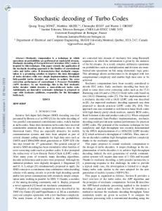
where λ0→i is the channel LLR available for bit i. A degree dv =3 variable node is shown in Figure 2, with its associated check node and channel LLR messages. λ0→i
Fig. 1. LDPC
Factor Graph and Parity Check Matrix H of Regular [3,6] N=16
i λi→j
(number of edge connections) dc : λj→i
� � d c Y λk→j . = 2 tanh−1 tanh 2
λl2 →i λl1 →i j
+
+
+
(1)
k=1
(k6=i)
The min-sum approximation to LLR BP decoding chooses the minimum incoming LLR magnitude as the outgoing LLR magnitude, with sign as the product of the message signs. Equation (1) can be rewritten as � � � � dc Y λk→j λj→i tanh = , (2) tanh 2 2 k=1 (k6=i)
where tanh(x)=(exp(x)-exp(−x))/(exp(x)+exp(−x)). Introducing the soft bit notation T =tanh(λ/2), equation (2) may be rewritten as dc Y Tj→i = Tk→j . (3) k=1
Fig. 2.
A degree dv =3 variable node and associated check messages
Moving into the soft bit domain, equation (4) becomes � � dv X λi→j λl→i (5) = tanh Ti→j = tanh . 2 2 l=0 l6=j
Using tanh(x+y)=(tanh(x)+tanh(y))/(1+tanh(x) tanh(y)), a degree 2 variable node message becomes
Ti→j = tanh
2 X l=0
l6=j
2 X
λl→i = 2
l6=j
1+
(k6=i)
This soft bit message has a fixed range (-1,+1). Linear quantization of the tanh message corresponds to nonlinear LLR quantization at larger values. A nonlinear LLR quantization scheme allows for representation of larger LLR magnitudes with fewer bits of precision. The LLR messages improve with increasing decoding iterations as they become more reliable, increasing in magnitude. A quantization scheme allowing representation of these larger LLR magnitudes, while also offering finer quantization of small LLR magnitudes for the initial decoding iterations, might provide better accuracy for less bit precision than a linear quantization scheme. The softbit message domain provides this with linear quantization which corresponds to a nonlinear LLR quantization. The check node computation for soft-bit decoding is the product of the incoming soft-bit messages. Products are easily implemented as Gilbert multipliers [13] in analog decoding circuits [14]. Because the soft bit message range is fixed to (-1,1), in digital circuits the quantized messages will be
Tλl→i
l=0
2 Y
.
(6)
node,
using
Tl→i
l=0
l6=j
Similarly for a degree 3 variable tanh(x+y+z)=tanh((x+y)+z), we obtain 3 X λl→i Ti→j = tanh 2 l=0
(7)
l6=j
3 X
Tl→i +
1+
3 X
l=0
l=0
=
3 Y Tl→i l6=j
l6=j
.
Tk→i Tl→i
k,l=0
k6=l6=j
We observe that, denoting the degree 2 variable node computation of equation (6) as T (x, y) and the degree 3 variable node computation of equation (7) as T (x, y, z), T (x, y, z) = T (T (x, y) , z)
(8)
3
Thus equation (7) may be implemented as two degree 2 variable node kernels, with the first taking as inputs x and y, and the second taking the resulting output and input z to produce equation (7). Higher degree representations of equation (5) can be found; the general variable equation consists of a top term of the sum of incoming messages plus cross-product terms with odd factors, i.e., Tl1 →i Tl2 →i Tl3 →i , and a bottom term of 1 plus even-factored cross-products, as Pdv l=0 Tl→i + odd factored crossproducts l6=i Ti→j = . (9) 1 + even factored crossproducts This form is quite complex and difficult to implement due to the many crossproducts. More simply, higher degree nodes can be represented as a function of degree 2 variable node kernels [15], just as for the degree 3 node. For example, a degree 7 variable node is computed as T (x1 , x2 , . . . , x7 ) = T (T (T (x1 , x2 ) , T (x3 , x4 )) , T (T (x5 , x6 ) , x7 )), using six degree 2 variable node kernels. A degree dv variable node requires dv − 1 degree 2 variable node kernels to exactly implement equation (9). In summary, a soft-bit-domain BP algorithm is implemented by performing products at check nodes and equation (5) at variable nodes. Higher degree variable nodes are subdivided into dv − 1 computational kernels which implement equation (9). The complexity shifts from the check nodes for LLRdomain BP decoding to the variable nodes in soft-bit decoding. A simplification of the variable node equation (9), suitable for VLSI implementation, is presented in the next Section. III. S IMPLIFICATION
OF THE
VARIABLE N ODE E QUATION
A general approximation for both variable node equation (6) and (9) can be written by noting that when incoming soft bit messages have magnitude near 1, the variable node equation approaches magnitude 1. For small-valued soft-bit messages, the cross-terms will be much smaller than the sum of the individual messages, and the variable node equation reduces to approximately the sum of the incoming messages. An approximation for any degree variable node is given by dv dv X X Tl→i , if | Tl→i | < 1; l=0 l=0 l6=j l6=j (10) Ti→j = dv dv X X sign( Tl→i ), if | Tl→i | ≥ 1; l=0 l=0 l6=j
Node
Equation P3
Ti→j =
Deg 3 Variable
l=0 l6=j
1+
Tl→i +
P3
k,l=0 k6=l6=j
Q3
l=0 l6=j
Tl→i
Tk→i Tl→i
Pdv Tl→i , if | l=0 Tl→i | < 1; l6=j l6=j � � Pdv , Ti→j = sign l=0 Tl→i l6= j Pdv if l=0 Tl→i ≥ 1;
Ti→j =
Variable Approx:
Pdv
l=0
l6=j
Tj→i =
Check
Qdc
Tk→j
k=1
(k6=i)
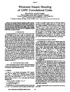
a rate 1/2 [3,6] LDPC code of codeword length N =1008 [16], over an AWGN (additive white Gaussian noise) channel with noise variance N0 /2. The all-zeros codeword is sent, using BPSK modulation. Plots show frame error rate (FER) versus signal-to-noise ratio (SNR) in dB. The signal-to-noise ratio is SNR=10 log10 (Eb /N0 ), where Eb is the energy per bit. Each FER value is calculated from 50+ frame errors, with 64 decoding iterations per frame. Both floating point and fixed point precision were examined. The bit precision includes a sign bit. Quantization to m bits results in 2m bins. Bin edges are placed at ±i/2m−1, ∀i = 0, 1, . . . , 2m−1 , with the quantized bin value set to the center value of the bin, located at ±(2i+1)/2m, ∀i = 0, . . . , 2m−1 − 1. Figure 3 displays fixed point sign-magnitude precision and soft-bit quantization, along with the corresponding nonlinear LLR quantization, for an m=4 bit message. Sign-Magnitude Bit Precision m − 1 bits z }| { sign
.
Soft-Bit Quantization
l6=j
However, this approximation becomes less accurate for higherdegree variable nodes, as the sum quickly goes to 1. This approximation should not be applied as a series of degree 2 computational kernels, or degradation of the approximation occurs. Table 1 summarizes the equations to be implemented at each node for each iteration of soft-bit BP decoding.
-1− 87
− 18 0 18
7 8
1
Corresponding LLR Quantization
-2.7 -1.95
-.25 .25
1.95
2.7
IV. R ESULTS Simulation results are presented for soft-bit decoding comparing equation (7) and approximation (10). Simulations used
Fig. 3. Bit Precision and Soft-Bit and Corresponding LLR Quantization for an m=4 bit sign-magnitude message
4
FER vs SNR: N=1008 M=512 [3,6] LDPC, tanh msgs
0
−1
10
−2
−1
10
−2
10
−3
10
−4
10
10
−5
10
1
Sum−Product Decoding: Floating pt Sum−Product: bit prec=4 bits Sum−Product: bit prec=5 bits Sum−Product: bit prec=6 bits Sum−Product: bit prec=7 bits 1.5
−3
10
−4
10
−5
10
1
1.5
2 SNR=Eb/N0
2 SNR=Eb/N0 in dB
2.5
3
Fig. 5. Signal-to-noise ratio (SNR) vs frame error rate (FER) for quantized LLR message decoding of N =1008 [3,6] LDPC code.
Exact tanh eqn at var: floating pt Exact: bit prec=4 bits Exact: bit prec=5 bits Exact: bit prec=6 bits Exact: bit prec=7 bits 2.5
3
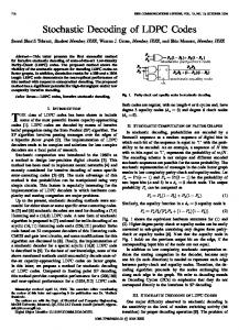
Fig. 4. Signal-to-noise ratio (SNR) vs frame error rate (FER) for soft-bit message decoding of N =1008 [3,6] LDPC code, with equation (7) at variable nodes.
In comparison, simulations using quantized LLR BP decoding with equations (1) and (4) for the same code were also performed. The last LLR λ bin edge and quantized value correspond to the associated last tanh(λ/2) soft-bit quantized value. Linear quantization determines the remaining bins. Results are shown in Figure 5. LLR BP decoding requires 7 bits of precision to achieve floating point results, the same as for soft-bit decoding using equation (7) at the variable nodes. Compared to floating point, 6 bits of precision costs 0.15 dB. Floating point results are the same for both LLR BP and softbit BP decoding, as expected since the two algorithms are equivalent. Figure 6 shows results using approximation (10) at the variable nodes, for both floating and fixed point precision. Floating point FER results for the approximation show a 0.5 dB loss compared to the exact soft-bit equation (7). The approximation requires 6 bits of precision to converge to floating point results; 5 bits of precision results in 0.1 dB loss. Table 2 summarizes our results for floating point and finite precision simulations of soft-bit and LLR BP decoding for the regular (3,6) N =1008 LDPC. Soft-bit decoding of a regular rate 0.667 (3,9) N =999 and rate 0.333 (4,6) N =996 LDPC was also examined, comparing the exact soft-bit equation (9) and approximation (10) at the variable nodes, for both floating and fixed point simulations. Results were similar to that of the regular (3,6) LDPC, with 0.5 dB loss due to the sum approximation. However, the lower rate (4,6) LDPC achieved floating point results with 1 less
FER vs SNR: N=1008 M=512 [3,6] LDPC, tanh msgs, approx
0
10 FER=frame error rate, 50+ frame errors
FER=frame error rate, 50+ frame errors
10
SNR vs FER, [3,6] N=1008 LDPC, LLR msgs
0
10 FER: frame error rate, 50+ frame errors
Figure 4 displays results for both floating and fixed point precision, using equation (7) at the variable nodes. Convergence to floating point results requires 7 bits of precision; approximately 0.1 dB loss is incurred using 6 bits of precision. Floating point FER results are consistent with BP decoding of the same code with LLR-domain messages.
−1
10
−2
10
−3
10
−4
10
−5
10
1
Exact tanh at var: floating pt SUM approx at var: floating pt SUM approx: bit prec=4 bits SUM approx: bit prec=5 bits SUM approx: bit prec=6 bits 1.5
2 SNR=Eb/N0
2.5
3
Fig. 6. Signal-to-noise ratio (SNR) vs frame error rate (FER) for soft-bit message decoding of N =1008 [3,6] LDPC code, with sum approximation (10) at variable nodes.
bit of precision, while the higher rate (3,9) LDPC required 1 additional bit of precision to achieve floating point results. LLR BP decoding was also examined, with the same results as exact soft-bit decoding in both floating and fixed point. Irregular LDPCs have varying, not constant, node degrees and are described by degree distributionsPλ and ρ. The variable i−1 , and λi is node degree distribution is λ(x) = i λi x the fraction of edges connecting to variable nodes of degree i. Likewise, the check node degree distribution is ρ(x) = P i−1 , and ρi is the fraction of edges to check nodes i ρi x of degree i.
5
Decoding Algorithm
Quantization Results
LLR BP Decoding
(11)
to a nonlinear quantization of the LLR messages, with fine quantization of small-valued LLRs and coarse quantization of larger LLRs. Higher degree variable nodes can be subdivided into degree 2 computational kernels, greatly simplifying their implementation. This subdivision is equivalent to the direct computation of equation (9). Additionally, a simple approximation to the more complex variable node processing in the soft-bit domain was presented. Simulation results for the sum approximation showed a 0.5 dB loss over exact soft-bit variable node decoding, but achieved floating point results with one less bit precision than the exact soft-bit variable node equation (9). The soft-bit decoding algorithm is well-suited to regular LDPCs. Due to poor performance of the sum approximation and high precision required for quantized exact soft-bit decoding, the soft-bit algorithm is not practical for irregular LDPCs. Soft-bit decoding offers another design option for both digital and analog decoder implementations. It provides alternate computational kernels easily implemented in analog devices, and quantization well-matched to the iteratively improving messages in LDPC BP decoding.
(12)
R EFERENCES
7 bits precision: floating pt 6 bits precision: 0.15 dB loss
LLR Min-Sum Approx
Floating Pt: 0.5 dB loss over BP
Soft-Bit BP Decoding
7 bits precision: floating pt 6 bits precision: 0.1 dB loss
Soft-Bit Approx
6 bits precision: floating pt 5 bits precision: 0.1 dB loss Floating Pt: 0.5 dB loss over BP
An irregular rate 0.5 LDPC with degree distribution λ(x) ρ(x)
= =
0.3078x + 0.2729x2 + 0.4193x8 7
8
0.4x + 0.6x
was also simulated. This degree distribution has a threshold SNR of 0.65 dB. Both the exact soft-bit equation (9), as implemented with degree 2 computational stages, and approximation (10) at the variable nodes were compared for floating point. While equation (9) provided equivalent results to LLR BP decoding, the sum approximation (10) did not, and in fact performed very poorly, with 1 dB and greater FER loss compared to the exact equation. The sum approximation typically overestimates (9). However, messages of mixed signs, where the sum is near zero, can also cause the wrong sign for the approximation. Degree 2 nodes do not suffer from this; however, as the variable degree increases, this problem increases. Subtracting off a small amount or scaling the messages to compensate for the overestimation in the manner of [17] to improve min-sum decoding did not improve soft-bit performance, as most of the approximation loss is not due to overestimated messages but to the incorrect output message sign. Additionally, quantization of equation (9) required 11 bits of precision to achieve floating point results, significantly more than for the regular LDPCs. The soft-bit algorithm is best suited for regular LDPCs and, due to the poor performance of the sum approximation and high bit precision required for good results with quantization of equation (9), is not recommended for irregular LDPCs. Very high variable degree regular LDPCs would most likely also suffer from poor sum approximation performance; however, the regular (4,6) LDPC examined gave good results. V. C ONCLUSIONS A novel representation of the BP decoding algorithm for LDPC codes which operates in the soft-bit domain rather than the LLR domain was derived and simulated. Use of soft-bit messages, which have a fixed range from (-1,1) instead of the infinite range of LLRs, allows for linear quantization of a nonlinear parameter, the tanh(LLR) messages. This is equivalent
[1] C. Berrou, A. Glavieux and P. Thitimajshima, ”Near Shannon limit error-correcting coding and decoding: Turbo-codes”, IEEE Intl. Conf. on Communications (ICC) 1993, pp. 1064-1070, May 1993. [2] R.G. Gallager, ”Low Density Parity Check Codes”, IRE Trans. on Inf. Theory, vol. IT-8, pp. 21-28, 1962. [3] L.R. Bahl, J. Cocke, F. Jelinek and J. Raviv, ”Optimal Decoding of Linear Codes for Minimizing Symbol Error Rate”, IEEE Trans. on Information Theory, vol. IT-20, pp. 284-287, March 1974. [4] J. Pearl, Probabilistic Reasoning in Intelligent Systems: Networks of Plausible Inference, San Mateo, CA, Morgan Kaufmann, 1988. [5] J. Hagenauer, E. Offer and L. Papke, ”Iterative decoding of block and convolutional codes”, IEEE Trans. on Inf. Theory, vol. IT-42, pp. 429445, March 1996. [6] M. Moerz, T. Gabara, R. Yan and J. Hagenauer, ”An Analog 0.25µ BiCMOS tailbiting MAP decoder”, Proc. of Intl. Solid-State Circuits Conf. (ISSCC) 2000, pp. 356-357, Feb. 2000. [7] V. Gaudet and G. Gulak, ”A 13.3-Mb/s 0.35µm CMOS Analog Turbo Decoder IC with a Configurable Interleaver”, IEEE Journal of SolidState Circuits, vol. 38, no. 11, pp. 2010-2015, Nov. 2003. [8] C. Winstead, J. Die, S. Yu, C. Myers, R. Harrison and C. Schlegel, ”CMOS Analog MAP Decoder for (8,4) Hamming Code”, IEEE Journal of Solid-State Circuits, vol. 39, no. 1, pp. 122-131, Jan. 2004. [9] A.J. Blanksby and C.J. Howland, ”A 690-mW 1-Gb/s 1024-b, rate-1/2 low-density parity-check code decoder”, IEEE Journal of Solid-State Circuits, vol. 37, no. 2, pp. 404-412, March 2002. [10] M.M. Mansour and N.R. Shanbhag, ”A 1.6 Gbit/s 2048-bit Programmable and Code-Rate Tunable LDPC Decoder Chip”, Proc. of 3rd Intl. Sym. on Turbo Codes, Brest, France, pp. 137-140, Sept. 2003. [11] T. Zhang and K. Parhi, ”A 56Mb/s (3,6)-Regular FPGA LDPC Decoder”, Proc. IEEE SIPS 2002, San Diego, CA, pp. 127-132, Oct. 2002. [12] N. Wiberg, H.-A. Loeliger and R. K¨otter, ”Codes and iterative decoding on general graphs”, European Trans. on Telecomm., pp. 513-525, Sept/Oct. 1995. [13] B. Gilbert, ”A precise four-quadrant multiplier with subnanosecond response”, IEEE J. of Solid-State Circuits, vol. 3, pp. 365-373, 1968. [14] H.-A. Loeliger, F. Lustenberger, M. Helfenstein and F. Tark¨oy, ”Probability Propagation and Decoding in Analog VLSI”, IEEE Trans. on Information Theory, vol. IT-47, pp. 837-843, Feb. 2001. [15] F. Kschischang, B.J. Frey and H.-A. Loeliger, ”Factor graphs and the sum-product algorithm”, IEEE Trans. on Information Theory, vol. IT-47, pp. 498-519, Feb. 2001. [16] D.J.C. MacKay, ”Encyclopedia of Sparse Graph Codes”, [Online]. Available: http://www.inference.phy.cam.ac.uk/mackay/codes/data.html. [17] J. Chen and M. Fossorier, ”Density Evolution for Two Improved BPBased Decoding Algorithms of LDPC Codes”, IEEE Communications Letters, vol. CL-6, pp. 208-210, May 2002.