Globecom 2014 - Optical Networks and Systems Symposium
Software-Defined DWDM Optical Networks: OpenFlow and GMPLS Experimental Study M. Bahnasy, K. Idoudi and H. Elbiaze Universit´e du Qu´ebec a` Montr´eal Email:
[email protected] Abstract—Finding an effective and simple unified control plane (UCP) for IP/Dense Wavelength Division Multiplexing (DWDM) multi-layer optical networks is very important for network providers. Generalized Multi-Protocol Label Switching (GMPLS) has been in development for decades to control optical transport networks. However, GMPLS-based UCP for IP/DWDM multi-layer networks is extremely complex to be deployed in a real operational products because still there are a lot of non-capable GMPLS equipments. DRAGON (Dynamic Resource Allocation via GMPLS Optical Networks) [1] is a software that solves this issue making these equipments capable for working in a GMPLS network. On the other hand, OpenFlow (OF), one of the most widely used SDN (Software Defined Networking) implementations, can be used as a unified control plane for packet and circuit switched networks [2]. In this paper, we propose and experimentally evaluate two solutions using OpenFlow to control both packet and optical networks (OpenFlow Messages Mapping and OpenFlow Extension). These two solutions are compared with GMPLS-based UCP. The experimental results show that the OpenFlow Extension solution outperforms the OpenFlow Messages Mapping and GMPLS solutions. Keywords—Optical Network; GMPLS; DRAGON; Software Defined Networking; OpenFlow
I.
I NTRODUCTION
Currently, IP and optical layers operate separately without dynamic interaction which leads to high operational cost, low network efficiency, and long processing latency for end-toend path provisioning. The main reason behind these limitations is that they are two different networks with different architectures, switching technologies, and control mechanisms. Therefore, a unified control plane (UCP) for both IP and optical layers, as one of the key challenges for the network carriers, is very important to address the aforementioned issue. GMPLS, a relatively mature control plane technique for optical transport networks, has been proposed as a solution for UCP [3]. But due to the distributed nature, the number of protocols, and the interactions between different layers, the GMPLS-based UCP is overly complex[4], [5]. Moreover, the implantation of this technology is difficult because still there are a lot of non-capable GMPLS equipments. DRAGON [6], is a software that solves this problem using SNMP (Simple Network Management Protocol) to control these equipments and making them capable for working in a GMPLS network. In this paper, we use this software and adapt it to operate with our optical switch (Cisco ONS 15454 1 ). On the other hand, we propose SDN [7] as a promising solution 1 ROADM
: Reconfigurable Optical Add-Drop Multiplexer
978-1-4799-3512-3/14/$31.00 ©2014 IEEE
2173
for a UCP. Generally, the SDN technology separates the control and data planes so that we can introduce a new functionality by writing a software program, running within an external controller that manipulates the logical map of the network. This provides the maximum flexibility for the operator to control different types of network, and match the carriers preferences. One of the widely used SDN implementations is OpenFlow [8]. OpenFlow protocol is mature for L2/L3 packet switching networks, but still at a starting stage for wavelengthswitched optical networks. So, it needs some extensions to be able to support the optical domain. Some efforts have been done to present OpenFlow-based UCP to control packet and circuit switches. Most notably, PAC.C [2] has experimented with alternative approaches. Other papers [9], [10], [11] have presented similar work as PAC.C by providing an experimental study or a Proof-of-Concept to support the using of OpenFlow as a unified control plane. However, [12] presents a comparison study between OpenFlow and GMPLS solutions based on a simulation. In this paper, we propose two approaches based on OpenFlow protocol to control both optical and electrical networks. Then we experimentally compare these two solutions with a real implementation of GMPLS approach. To the best of our knowledge, this is the first work who considers both OpenFlow and GMPLS UCP solutions, and compare them via testbed experimentation. We conduct a real case study of implementing end-to-end lightpath and a lightpath restoration by establishing a dynamical configured backup lightpath. The first solution is OpenFlow Messages Mapping; we map the OpenFlow standard messages into equivalent optical channel requests, without modifying the OpenFlow protocol. The second one is OpenFlow Extension; new messages have been added to the OpenFlow protocol in order to support the circuit switching. The proposed solutions are implemented in a testbed to demonstrate their effectiveness, as well as GMPLS-based approach. For both solutions, we implement an OpenFlow Optical Agent to translate the OpenFlow messages to be executed on the optical switches. Moreover, a Path Computation Element (PCE) module is added to the OpenFlow controller as a network application in order to control the optical domain. The remaining of this paper is organized as follows; Section II describes how can OpenFlow define a unified control plane for both IP and optical networks and the iplementation of the proposed solutions (OpenFlow Messages Mapping and OpenFlow Extension). Section III presents the GMPLS-based UCP approach and the deployment of this protocol in our testbed. In particular, we explain the adaptation of DRAGON software for our ROADM (CISCO ONS 15454). Section IV
Globecom 2014 - Optical Networks and Systems Symposium
presents the different experimental scenarios for each solution and the comparative results with GMPLS. Concluding remarks are eventually given in section V. II.
O PEN F LOW- BASED U NIFIED C ONTROL P LANE
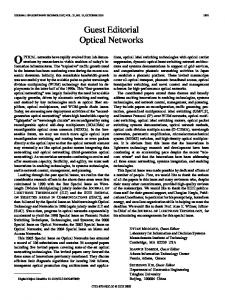
A. Overview We briefly outline the main characteristics of OpenFlow. A more detailed and exhaustive documentation is available in the OpenFlow white paper [13] and in the Open Flow specification [14]. OpenFlow is an open standard that was developed several years ago at Stanford University in order to enable researchers to run experimental new protocols and technologies on real networks, without disrupting the existing traffic or network availability [15]. In a traditional network, the data path and the control path occur on the same device (switch, router). OpenFlow separates these two functions; OpenFlow switches perform the data plane functions and OpenFlow controller implements the control plane intelligence and communicates with the OpenFlow switch via the OpenFlow protocol. An OpenFlow switch consists of one or more flow tables and group tables, which perform packet lookups and forwarding, and a secure channel that is connected to an external controller. Each flow table in the switch contains a set of flow entries; each flow entry consists of match fields, counters and a set of instructions to apply to matching packets. OpenFlow advocates the separation of data and control planes for circuit and packet networks, as well as the treatment of packets as part of flows, where a packet flow is defined as any combination of L2/L3/L4 headers. This, together with L1/L0 circuit flows, provides a simple flow abstraction that fits well with both types of networks. Hence, OpenFlow presents a common platform for the control of the underlying switching hardware, that switches flows of different granularities, while allowing all of the routing, control and management to be defined in software outside the datapath, in the OpenFlow controller (Figure 1).
controller as a network application (Figure 2). Upon request arrival, PCE calculates the corresponding lightpath and sends the cross-connection messages to involved ROADMs. In the next sections, we describe OpenFlow Messages Mapping and OpenFlow Extension solutions. 1) OpenFlow Messages Mapping: In this solution, the OpenFlow standard messages are used without any modification. The OpenFlow messages are mapped into optical switch commands. In this approach, the OFPT FLOW MOD message of type OFPFC ADD is mapped into ENT-OCHNC TL1-command to create a lightpath channel. The OFPT FLOW MOD message of type OFPFC DELETE is mapped into DLT-OCHNC TL1-command to delete a lightpath channel. When the agent receives OFPT FEATURES REQUEST message, it encapsulates the emulated port information into OFPT FEATURES REPLY message. Finally the agent reads periodically the ROADM events (using RTRV-ALM-ALL TL1-command) and if it finds any critical alerts, it creates OFPT PORT STATUS message and forwards it to the controller. 2) OpenFlow Extension: In this solution, OpenFlow messages are extended and new messages are added. The new messages specification [17] allows the controller to distinguish between the circuit-switching and the packet-switching networks. For example, OFPT FEATURES REPLY message is extended by adding extra information about the circuitswitching ports. To send an optical cross-connect information, a new match structure called ofp connect is presented. Multiple ports can be cross-connected by a single structure. This structure is added to the newly defined message called OFPT CFLOW MOD. Finally when the state of a port changes, the OpenFlow Optical Agent sends a new defined message called OFPT CPORT STATUS. C. OpenFlow Optical Agent As mentioned above, the main role of the OpenFlow Optical Agent is to translate the optical channel requests and OpenFlow messages into TL1 commands to be executed on optical nodes (Figure 2).
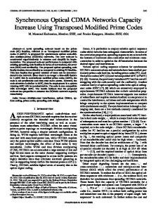
Fig. 1: Unified architecture of a converged Packet-Circuit network B. OpenFlow Messages Mapping and OpenFlow Extension This paper proposes two solutions using OpenFlow protocol as a unified control plan for both optical and electrical domains (OpenFlow Messages Mapping and OpenFlow Extension). For both solutions, we implement an OpenFlow Optical Agent to translate the OpenFlow messages to its proper TL1 (Transaction Language 1) commands [16] to be executed on the optical switch using telnet channel. A Path Computation Element (PCE) module is added to the OpenFlow
2174
Fig. 2: OpenFlow Optical Agent intercations This agent is associated to each optical node and acts as a virtual switch. It consists of ; (i) OpenFlow
Globecom 2014 - Optical Networks and Systems Symposium
Channel to communicate with the OpenFlow controller, (ii) OpenFlow/TL1 Translator to convert OpenFlow messages into TL1 commands, and (iii) Ports Emulation module to emulate the optical node ports and send the port status information to the controller. This information is used by the controller to update ports database and to calculate the lightpath 1 .
via WSS (Wavelength Selective Switch) and DMX (Channel Demultiplexer) cards, whereas ROADM core interfaces are interconnected via LINE cards. Two fibers are used for the bidirectional connection between two ROADMs. These specifications lead us to add this module. III.
GMPLS- BASED U NIFIED C ONTROL P LANE
D. Path Computation Element (PCE)
A. Overview
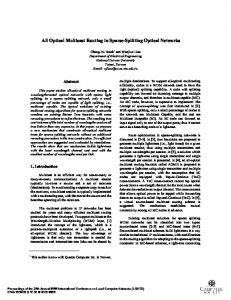
The PCE implements an algorithm to establishe lightpaths between source-destination pairs in order to create a fully connected logical topology [18]. A Traffic Engineering Database (TED) is created to save the network topology information. As the OpenFlow controller has a centralized management, the TED will be updated in case of lightpath creation/release and ports status change. Two modules are proposed to implement the PCE; Executor and Optical Switch Adapter (Figure 3).
Actually, there are still a lot of non capable GMPLS equipments. DRAGON software solves this problem in the Ethernet networks using SNMP to adapt these equipments to GMPLS control plane. The DRAGON project studies and develops an open source software to enable dynamic provisioning of network resources on an interdomain basis across heterogeneous network technologies. The project enables the communication between networks of different types through the GMPLS control suite. For its implementation, DRAGON deploys the IP network infrastructure and creates a GMPLS capable optical core network to allow dynamic provisioning of deterministic network paths in direct response to end-user requests, spanning multiple administrative domains. Optical transport and switching equipments acting as Label Switching Routers (LSRs) provide deterministic network resources at the packet, wavelength, and fiber cross-connect levels. B. DRAGON Control Plane Components DRAGON software is thought to work like control plane within a GMPLS network. The control plane architecture consists of two basic elements 2 : The Client System Agent (CSA) and Virtual Label Switch Router (VLSR).
Fig. 3: Path Computation Element workflow 1) Executor: This module ensures the avoidance of using one wavelength more than once in the same fiber. Each wavelength carries traffic between a pair of source and destination. Therefore, multiple wavelengths are reserved in a single strand of fiber for establishing multiple lightpath through one fiber. These connections between source/destination nodes in DWDM networks are performed in two steps: •
Routing: We use Dijkstra Algorithm in order to find the shortest path between each node pair. In our case, we are interested in a network topology composed of OpenFlow switches and ROADMs.
•
Wavelength Assignment: Once the lightpath routes are determined, the wavelength assignment problem can be represented as a graph coloring problem. Each lightpath corresponds to a node in wavelength assignment graph, and two nodes are set as neighbors only if the respective lightpaths share at least one common link.
2) Optical Switch Adapter: Each ROADM consists of a set of cards and each card contains a set of configured ports [19]. ROADM edges are connected to OpenFlow switches 1 Ports
1) CSA (Client System Agent): The CSA is a software that runs on (or on behalf of) any system which terminates the data plane (traffic engineering) link of the provisioned service. This is the software that participates in the GMPLS protocols to allow for on demand end-to-end provisioning from client system to client system. A CSA can be a host, a router, or any networked device. 2) VLSR (Virtual Label Switch Router): GMPLS has not yet been implemented on large a scale. There are still a lot of non GMPLS capable switches in use. To overcome this limitation, the DRAGON protocol suite uses the VLSR. A VLSR is used to control different kinds of switches like for instance Ethernet, TDM or Optical switches. What a VLSR does besides participating in the GMPLS protocols is translating GMPLS commands into switch specific commands like SNMP. By the use of these commands, a VLSR can control the switch and for example set a switch port in the specific VLAN. To communicate with other VLSRs and CSAs, a VLSR uses the routing protocol OSPF-TE (Open Shortest Path FirstTraffic Engineering) and path signaling protocol RSVP-TE (Resource Reservation Protocol-Traffic Engineering). A VLSR uses OSPF-TE to get familiar with the control plane network and to inform the VLSRs and CSAs in the control plane about the TE network links. A VLSR uses the OSPF-TE LSAs (Link State Advertisements) to send information about the TE links. 2 The informations found in this section is based on the Sara Project documentation produced by the RFC 3945 [20]
discovery is out of scope in this paper
2175
Globecom 2014 - Optical Networks and Systems Symposium
Information that could be send over the control plane is information about upcoming and down going LSPs (Label Switched Paths). The OSPF-TE works with two daemons called OSPFD and zebra. Zebra, or GNU Zebra [21], is routing software for managing TCP/IP based routing protocols like RIP, BGP and OSPF. The DRAGON software extends the OSPF routing daemon with Traffic Engineering informations like bandwidth, WDM and TDM used by GMPLS. A VLSR uses RSVP-TE for signaling and setting up LSPs within the GMPLS network. The RSVP-TE protocol originates from the Technische Universitt Darmstadts KOMRSVP [22]. The DRAGON software extends the KOM-RSVP signaling protocol with support for RSVP-TE, GMPLS, Q-Bridge, SNMP and VLAN control. C. Adapting VLSR for Cisco ONS 15454 The DRAGON software suite is being developed under the GNU General public license [23]. The source code can be viewed, changed for own use. The latest version of the software suite can be downloaded at [24]. In order to install the DRAGON software, the VLSR implementation guide has been followed [25]. By default, the VLSR PC uses SNMP RFC 2674 to communicate with switch. To manage and control the Cisco ONS 15454, we use TL1 commands. Thus, we implement an SNMP/TL1 Gateway that acts as a proxy to adapt the VLSR software with Cisco ONS 15454 specification (Figure 4). As shown in figure
1) Testbed Setup: The architecture of our testbed is depicted by figure 5. It consists of two clients A and B, which are connected directly to OpenFlow switches 1 and 2, respectively. Each switch is connected to an Electrical/Optical converter. These converters are connected to DWDM optical network composed of three Cisco ROADM optical switches (Cisco ONS 15454). Each ROADM is controlled by an OpenFlow Optical Agent. The OpenFlow optical agents and the OpenFlow switches are connected to an OpenFlow controller over an OpenFlow channel. 2) Scenario 1: End-to-End Lightpath Setup: As shown in Figure 5, a data flow sent from Client A to Client B arrives at OpenFlow switch1. When the OpenFlow switch1 does not find any flow entry that matchs with this flow, it encapsulates the first flow packet in an OFPT PACKET IN message and forwards it to the Controller. Then the controller uses the PCE to calculate the lightpath, and creates the lightpath by sending OFPT FLOW MOD message (OpenFlow Messages Mapping solution) or OFPT CFLOW MOD message (OpenFlow Extension solution) to the switches. The connection is established between the two clients following steps A1, A2, A3, A4, A5, A6, and A7 (Figure 5). The wireshark screenshot presents the exchanged messages during this scenario (Figure 6).
Fig. 4: SNMP/TL1 Gateway 4, the SNMP/TL1 Gateway is composed of two modules: •
SNMP Agent: Using snmp4j [26] open source Java library, we have developed an SNMP agent. It provides functions to receive and send SNMP PDUs (Protocol Data Unit).
•
TL1 Agent: Using the iReasing [27] TL1 API, we have developed a TL1 based management application that communicates with the Cisco ONS 15454. Its main function is to map the SNMP messages into TL1 commands to set-up configurations in Cisco ONS 15454. IV.
E XPERIMENTAL SETUP
In this section, we first present the OpenFlow experiments followed by the GMPLS ones. Then we discuss the experimental results in order to evaluate and compare the OpenFlow solutions with GMPLS. A. OpenFlow Experiments Two experiments are conducted to demonstrate the efficacy of our proposed solutions. The first experiment consists of creating end-to-end lightpath while the second experiment performs a backup restoration lightpath when failure occurs on the primary lightpath.
2176
Fig. 6: OpenFlow Scenario1 : Wireshark screenshot 3) Scenario 2: Shared Optical Restoration: This scenario demonstrates how OpenFlow controller acts when a link failure occurs. The path deletion is performed by the controller using OFPFC DELETE message. Figure 5 shows the steps that are executed in this scenario (B1, B2, B3, B4, and B5). The wireshark screenshot presents the exchanged messages during this scenario (Figure 7). B. GMPLS Experiments To experiment GMPLS, we construct a transparent optical network testbed with two ROADMs (Figure 8). In this infrastructure, the control plane consists of two CSAs and two VLSRs. The CSAs and the VLSRs are connected via the switch hub. GRE (Generic Routing Encapsulation ) tunnels are created between the CSAs and the VLSRs and between the VLSRs themselves to exchange RSVP-TE and OSPF-TE messages. The SNMP/TL1 Gateway has a connection with the switch hub to allow SNMP management by the VLSRs.
Globecom 2014 - Optical Networks and Systems Symposium
Fig. 5: Network configuration and exchanged messages during the OpenFlow experiments It translates SNMP messages to TL1 commandes in order to configure the ROADMs. In the SNMP/TL1 Gateway machine, we installed two virtual machines. Each one listens to a VLSR on port 161 and controls one ROADM. Using wireshark capture in VLSR2 (Figure 9 (a)) and VLSR1 (Figure 9 (b)), we explain the GMPLS signaling to create an LSP from CSA2 to CSA1. CSA2 sends RSVP PATH message to VLSR2 with the destination set to the target CSA1. Both VLSRs forward the path message since they are not the destination. When CSA1 receivs
2177
the RSVP PATH message, it replies to it with RSVP RESV message and sends it to VLSR1. VLSR1 forwards this message to VLSR2 because again it is not the destination of the message. Finally, VLSR2 forwards the RSVP RESV message to CSA2. At this point, the LSP is active and can be used. The SNMP/TL1 Gateway translates the SNMP messages sent by the two VLSRs to TL1 commands in order to configure the two ROADMs.
Globecom 2014 - Optical Networks and Systems Symposium
Fig. 8: DRAGON test with two ROADMs
Fig. 7: OpenFlow Scenario2 : Wireshark screenshot C. Experimentation Results Table I shows the time (in ms) consumed on each solution (OpenFlow Messages Mapping and OpenFlow Extension) and the GMPLS approach. In this table, Path1 and Path2 refer to the primary and the backup lightpaths. Path1 nodes are OF Switch1 → ROADM2 → ROADM3 → OF Switch2, while Path2 nodes are OF Switch1 → ROADM2 → ROADM1 → ROADM3 → OF Switch2. LSP on the table refers to Label Switch Path for GMPLS. LSP nodes are CSA1 → ROADM2 → ROADM3 → CSA2. The experiments results show that OpenFlow Extension solution (216 ms) outperforms OpenFlow Messages Mapping (227 ms) solution. This result is expected because OpenFlow Extension solution uses one message to encapsulate bidirectional lightpath information
2178
Fig. 9: GMPLS Scenario : Wireshark screenshot and OpenFlow Messages Mapping needs two messages. For the backup lightpath (Path2) which span on three nodes, OpenFlow Extension solution takes 239 ms to create the lightpath while OpenFlow Messages Mapping takes 269 ms.
Globecom 2014 - Optical Networks and Systems Symposium
Controller Path1 Path2
16 18 Controller
Path1 Path2
16 18 RSVP-TE
LSP
130
OpenFlow Messages Mapping Solution Switch establishment ROADM2 ROADM1 ROADM3 121 90 110 30 111 OpenFlow Extension Solution Switch establishment ROADM2 ROADM1 ROADM3 100 100 90 30 101 GMPLS Solution Switch establishment ROADM2 ROADM1 ROADM3 110 100
[4]
Total (ms) 227 269
[5] Total (ms) 216 239
[6]
Total (ms) 340
[7]
TABLE I: The experiments timing [8]
On the other hand, GMPLS takes more time (340 ms) to create lightpath than OpenFlow solutions. This is because the GMPLS-based control plane is complicated especially when it is deployed as a unified control plane (UCP) for IP/DWDM multi-layer networks. This is due to its distributed nature, the number of protocols, and the interactions among different layers. The flexibility and manageability of the GMPLS-based control plane is low, because, for example, if we want to create or update an end-to-end lightpath, the signalisation and reservation messages must be updated and exchanged between all the intermediate VLSRs. However, the OpenFlow-based UCP provides the maximum flexibility and manageability for carriers since all the functionalities are integrated into a single OpenFlow controller. More importantly, the OpenFlow-based control plane is a natural choice for a UCP in IP/DWDM multilayer networks due to its inherent feature, as the procedure shown in Figure 5. Thus, the technical evolution from GMPLS to OpenFlow is a process that the control plane evolves from a fully distributed architecture to a fully centralized one.
[9]
[10]
[11]
[12]
[13] [14] [15]
V.
C ONCLUSION
In this paper, we experimentally present two solutions (OpenFlow Messages Mapping and OpenFlow Extension) for a dynamic wavelength path control in IP/DWDM multilayer optical networks. The overall feasibility of these solutions is experimentally assessed, and their performance is quantitatively evaluated and compared with GMPLS approach, on an actual transparent network testbed. The comparison reveals that the OpenFlow-based control plane is simpler, more flexible and manageable than the GMPLS-based control plane, especially for an IP/DWDM multi-layer optical network. Finally, the experimental results show that the OpenFlow Extension solution outperforms the OpenFlow Messages Mapping and GMPLS solutions. It can significantly improve the performance of the control plane and reduce the lightpath setup time.
[16] [17]
[18]
[19]
[20] [21] [22] [23] [24]
R EFERENCES [1]
“DRAGON: Dynamic Resource Allocation via GMPLS Optical Networks,” http://dragon.east.isi.edu/twiki/bin/view/DRAGON/WebHome. [2] S. Das, G. Parulkar, N. McKeown, P. Singh, D. Getachew, and L. Ong, “Packet and circuit network convergence with openflow,” in Optical Fiber Communication (OFC), collocated National Fiber Optic Engineers Conference, 2010 Conference on (OFC/NFOEC), March 2010, pp. 1–3. [3] E. Mannie, “Generalized multi-protocol label switching (gmpls) architecture,” Interface, vol. 501, p. 19, 2004.
2179
[25] [26] [27]
L. Liu, T. Tsuritani, and I. Morita, “Experimental demonstration of openflow/gmpls interworking control plane for ip/dwdm multi-layer optical networks,” in Transparent Optical Networks (ICTON), 2012 14th International Conference on. IEEE, 2012, pp. 1–4. Y. Zhao, J. Zhang, H. Yang, and Y. Yu, “Which is more suitable for the control over large scale optical networks, gmpls or openflow?” in Optical Fiber Communication Conference and Exposition and the National Fiber Optic Engineers Conference (OFC/NFOEC), 2013, 2013, pp. 1–3. T. Lehman, J. Sobieski, and B. Jabbari, “Dragon: a framework for service provisioning in heterogeneous grid networks,” Communications Magazine, IEEE, vol. 44, no. 3, pp. 84–90, March 2006. “SDN: Software Defined Networking,” https://www.opennetworking.org/sdn-resources/sdn-definition. “OpenFlow,” https://www.opennetworking.org/sdn-resources/onfspecifications/openflow. L. Liu, T. Tsuritani, I. Morita, H. Guo, and J. Wu, “Openflow-based wavelength path control in transparent optical networks: a proof-ofconcept demonstration,” in Optical Communication (ECOC), 2011 37th European Conference and Exhibition on. IEEE, 2011, pp. 1–3. L. Liu, D. Zhang, T. Tsuritani, R. Vilalta, R. Casellas, L. Hong, I. Morita, H. Guo, J. Wu, R. Mart´ınez et al., “Field trial of an openflow-based unified control plane for multilayer multigranularity optical switching networks,” Journal of Lightwave Technology, vol. 31, no. 4, pp. 506–514, 2013. L. Liu, D. Zhang, T. Tsuritani, R. Vilalta, R. Casellas, L. Hong, I. Morita, H. Guo, J. Wu, R. Martinez, and R. Munoz, “First field trial of an openflow-based unified control plane for multi-layer multigranularity optical networks,” in Optical Fiber Communication Conference and Exposition (OFC/NFOEC), 2012 and the National Fiber Optic Engineers Conference, March 2012, pp. 1–3. A. Giorgetti, F. Cugini, F. Paolucci, and P. Castoldi, “Openflow and pce architectures in wavelength switched optical networks,” in Optical Network Design and Modeling (ONDM), 2012 16th International Conference on. IEEE, 2012, pp. 1–6. http://www.openflow.org/documents/openflow-wp-latest.pdf. O. S. Consortium et al., “Openflow switch specification version 1.0. 0,” 2009. N. McKeown, T. Anderson, H. Balakrishnan, G. Parulkar, L. Peterson, J. Rexford, S. Shenker, and J. Turner, “Openflow: enabling innovation in campus networks,” ACM SIGCOMM Computer Communication Review, vol. 38, no. 2, pp. 69–74, 2008. C. Headquarters, “Tl1 command reference for the cisco ons 15808 dwdm system,” 2003. S. Das, “Extensions to the openflow protocol in support of circuit switching,” Addendum to OpenFlow protocol specification (v1. 0)Circuit Switch Addendum v0, vol. 3, 2010. V. Tintor and J. Radunovi´c, “Multihop routing and wavelength assignment algorithm for optical wdm networks,” International Journal of Networks and Communications, vol. 2, no. 1, pp. 1–10, 2012. “Cisco ONS 15454 DWDM Reference Manual, Release 9.2,” http://www.cisco.com/en/US/docs/optical/15000r9 2/dwdm/reference/guide/ 454d92 ref.html/, 2012. “RFC 3945 Generalized Multi-Protocol Label Switching (GMPLS) Architecture,” http://www.ietf.org/rfc/rfc3945.txt. “GNU Zebra,” http://www.gnu.org/software/zebra/. “KOMRSVP Engine,” http://www.kom.tudarmstadt.de/en/downloads/software/komrsvp- engine/ . “GNU General Public License,” http://www.gnu.org/copyleft/gpl.html. “DRAGON Source Code,” http://Dragon.maxgigapop.net/public/Dragonswvlsr-daily.tar.gz. http://dragon.east.isi.edu/twiki/pub/DRAGON/VLSR/dragon-vlsrimplement-v2.1b.pdf. “SNMP4J API,” http://www.snmp4j.org/. “iReasoning TL1 API,” http://ireasoning.com/tl1api.shtml.


![Optical Networks [Book Reviews] - IEEE ... - IEEE Xplore](https://m.moam.info/img/260x300/optical-networks-book-reviews-ieee-ieee-xplore_59dba1291723dd46dfe54bf8.jpg)