EuroSTAR'94, 10-13 October 1994, Conrad International Hotel, Brussels, Belgium
Software Testing Strategies for Software Requirements and Design Wachara Chantatub and Prof. Mike Holcombe Dept. of Computer Science, University of Sheffield, Regent Court, 211 Portobello Street, Sheffield, S1 4DP, UK Tel: +44 742 768555 ext. 5599 Fax: +44 742 780972 Email:
[email protected] [email protected]
Abstract Software requirements testing and software design testing are very important and must be taken seriously. Specifications of software requirements and design must be verified and validated before the implementation. Many individuals involved in design still find that some of the techniques available for these tasks are difficult and far from practical. This paper presents simple and very practical techniques for these tasks. The suggested techniques emerge from integrating three specification techniques, namely an informal specification technique (English language), a semi-formal specification technique (graphical models, namely entity-relationship diagram, data flow diagram, and data structure diagram), and a formal specification technique (a slightly extended version of the language Z). The three techniques mentioned above are very useful for different aspects and by using all of them in combination will provide practical and efficient techniques for the above mentioned tasks. However, by just simply using them as usual does not provide satisfactory results, therefore, we adapt and modify them to achieve software requirements and design specifying and testing techniques that are capable of providing satisfactory results. In this paper, we discuss: 1) how to draw the diagrams, we will suggest new ideas of how to draw the diagrams; 2) how to write formal specifications for software requirements and design, we will suggest new ideas of how to write formal specification using the extended Z specification language; 3) how to apply informal and formal proofs to verify and validate software requirements specification and software design specification; 4) the procedures of some of the tasks concerned. We do believe that the suggested techniques will be found useful, not too difficult, and efficient, especially for business information systems. Prerequisite Key Words: Structured Analysis and Design Method, Z Topic Descriptors: Software Requirements Testing, Software Design Testing, Test Management
Wachara Chantatub & Prof. Mike Holcombe
Software Testing Strategies for Software Requirements and Design
40/1
EuroSTAR'94, 10-13 October 1994, Conrad International Hotel, Brussels, Belgium
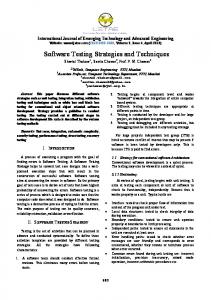
1. Introduction Specifying and testing software requirements and design are very important tasks in software development and must be taken seriously. By investing more up-front effort in these tasks, the project will gain the benefits of reduced maintenance costs, higher software reliability, and more user-responsive software [1]. Good software specifications should have these properties: understandability, correctness, completeness, consistency, testability, and maintainability [1]-[3]. At the moment, one of the best solutions to achieve the good software specifications is by integrating three specification techniques, namely informal specification technique (natural language), semi-formal specification technique (graphical models, e.g. entityrelationship diagram, data flow diagram, and data structure diagram), and formal specification technique (e.g. Z, VDM, OBJ). So far there have already been quite a number of researches in this area, for example [4]-[7], although few, apart from [6], have considered the needs of testing. In this paper, we present new techniques for specifying and testing software requirements and design which emerge from integrating the three specification techniques mentioned above. In our proposed techniques, informal specifications are written in English statements, semi-formal specifications are in forms of entityrelationship diagrams, data flow diagrams, and data structure diagrams, and formal specifications are written in Z. In this paper, we present: 1) how to draw the diagrams, we will suggest new ideas of how to draw the diagrams; 2) how to write formal specifications for software requirements and design, we will suggest new ideas of how to write formal specification using the extended Z specification language; 3) how to apply informal and formal proofs to verify and validate software requirements specification and software design specification; 4) the procedures for managing some of the tasks concerned. One of the most suitable ways of specifying software requirements and design of a system is specifying them in terms of static and dynamic aspects of the system. The static aspect of a system is concerned with entities (things of importance to a system about which data needs to be stored) and their relationships. The dynamic aspect of a system is concerned with processes that change the state or relationships of the entities or enquire about information of the system. Regarding informal specifications, normally the two aspects are mingled. Regarding semi-formal specifications, the static aspect can be specified by using an entity-relationship diagram and the dynamic aspect can be specified by using a data flow diagram [5]. An entity-relationship diagram and a data flow diagram are no doubt the most outstanding and the most well-known semiformal specification techniques. Even though these two diagrams are very useful, they are not rigorous enough since it is hard to reason about them, particularly with automated proof systems, and they can be ambiguous. Therefore, formal specifications are needed in order to be able to specify the system more rigorously. We consider using Z, suitably extended as our formal specification language because it has many good properties for the task. The proposed techniques are linked together to form the model of specifying and testing software requirements and design as shown in figure 1. The numbers shown in figure 1 represent steps in the model.
Wachara Chantatub & Prof. Mike Holcombe
Software Testing Strategies for Software Requirements and Design
40/2
EuroSTAR'94, 10-13 October 1994, Conrad International Hotel, Brussels, Belgium
1 Informal requirements specification (English statements)
7 Informal proof
6 Informal design specification (English statements)
3 Informal proof
5 Informal proof
2 Semi-formal requirements specification (RERD,,RDFD, RDSD)
9 Informal proof
9 Informal proof
8 Semi-formal design specification (DERD,DDFD,DDSD)
5 Informal proof
4 Formal requirements specification (Z specifications)
11 Informal proof
11 Informal proof
11 Formal proof
10 Formal design specification (Z specifications)
Formal proof
Formal proof
5
11
Figure 1: The model of specifying and testing software requirements and design The steps in the model can be described as follows: 1. Informal requirements specification is specified, stated in English statements. 2. Semi-formal requirements specification is specified, in other words, we draw required entity-relationship diagrams (RERD), required data flow diagrams (RDFD), and required data structure diagrams (RDSD), by using information from the informal requirements specification. 3. Informal proof is applied to verify and validate the semi-formal requirements specification against the informal requirements specification. 4. Formal requirements specification is specified, in other words, we write requirements specifications in our extended Z specification language, by using information from both the informal requirements specification and the semiformal requirements specification. 5. Informal proof is applied to verify and validate the formal requirements specification against both the informal requirements specification and the semiformal requirements specification. At this stage we can construct formal requirements test cases to assist in the validation. In addition, formal proof is applied to prove consistency and correctness within the formal requirements specification itself. 6. Informal design specification is specified, stated in English statements, by using information from the informal requirements specification. 7. Informal proof is applied to verify and validate the informal design specification against the informal requirements specification. 8. Semi-formal design specification is specified, in other words, we draw designed entity-relationship diagrams (DERD), designed data flow diagrams (DDFD), and designed data structure diagrams (DDSD), by using information from both Wachara Chantatub & Prof. Mike Holcombe
Software Testing Strategies for Software Requirements and Design
40/3
EuroSTAR'94, 10-13 October 1994, Conrad International Hotel, Brussels, Belgium
the informal design specification and the semi-formal requirements specification. 9. Informal proof is applied to verify and validate the semi-formal design specification against both the informal design specification and the semi-formal requirements specification. 10. Formal design specification is developed, in other words, we write design specifications in our extended Z specification language, by using information from the informal design specification, the semi-formal design specification, and the formal requirements specification. 11. Informal proof is applied to verify and validate the formal design specification against both the informal design specification and the semi-formal design specification. In addition, formal proof is applied to prove consistency and correctness within the formal design specification itself and of the formal design specification against the formal requirements specification. Again, design test sets can be generated from the formal specification for validation purposes. At the end of the step 5, a complete requirements specification can be obtained by integrating the three requirements specifications produced in a proper order. Also, at the end of the step 11, a complete design specification can be obtained by integrating the three design specifications produced in a proper order. Since each specification is informally and/or formally proved against the related specification(s), we feel more confident in the software requirements specification and the software design specification produced. In section 2, we discuss the differences between software requirements specification and software design specification. In section 3, we state an example system used throughout this paper. In section 4, we explain how to specify and test software requirements specifications. In section 5, we explain how to specify and test software design specifications. In section 6, we conclude our approach and discuss our findings.
2. The Differences between Software Requirements Specification and Software Design Specification It is important to state clearly the differences between software requirements specification and software design specifications. First of all, we define them as follows. A software requirements specification is a document containing a complete description of the requirements of a system; it states from the end-user's point of view what the system will do without describing how it will do it [3]. It must correctly define all of the software requirements, but no more, and it should not describe any design [8]. A software design specification is a document containing a complete description of the design of a system; it states from the designer's point of view what the system will do in order to satisfy the requirements stated in the software requirements specification without describing how it will implement it. It is a translation of requirements into a description of the software structure, software components, interfaces, and data necessary for the implementation phase [9]. So far, there is no clear boundary between software requirements specification and software design specification. As stated by Davis in [3] concerning "the what versus how" dilemma in which one person's requirements specification might be considered as another person's design specification and vice versa. However, in order to be able to present our techniques, we need to state the boundary which we use to distinguish Wachara Chantatub & Prof. Mike Holcombe
Software Testing Strategies for Software Requirements and Design
40/4
EuroSTAR'94, 10-13 October 1994, Conrad International Hotel, Brussels, Belgium
between these two specifications. The boundary used may be varied depending on what are considered to be design decisions, not user's requirements. In this paper, we assume that designers use data modelling methods [10] as their design concept. Therefore, the design specification will capture the design decisions arising as a result of applying the data modelling method. Data modelling provides a basis for conceptualizing data intensive applications; it involves the design of a conceptual data model which is an abstraction of the real-world data and the design of a logical data structure, representing the conceptual data model, which will be mapped onto an actual implementation.
3. An Example System An example system used throughout this paper is the library system as stated in the Fourth International Workshop on Software Specifications and Design [11] as follows. Consider a small library database system with the following transactions: 1. Check out a copy of a book / Return a copy of a book; 2. Add a copy of a book to / Remove a copy of a book from the library; 3. Get the list of books by a particular author or in a particular subject area; 4. Find out the list of books currently checked out by a particular borrower; 5. Find out what borrower last checked out a particular copy of a book. There are two types of users: staff users and ordinary borrowers. Transactions 1, 2, 4, and 5 are restricted to staff users, except that ordinary borrowers can perform transaction 4 to find out the list of books currently borrowed by themselves. The database must also satisfy the following constraints: 1. All copies in the library must be available for check out or be checked out. 2. No copy of the book may be both available and checked out at the same time. 3. A borrower may not have more than a predefined number of books checked out at one time.
4. Specifying and Testing Software Requirements To keep the example simple, we assume that the information given in section 3 is the informal requirements specification produced from step 1, even though the actual informal requirements specification must be a lot more elaborate than this one. The next step to be carried out is step 2, specifying a semi-formal requirements specification. 4.1 Specifying semi-formal requirements specification The outputs of this step are a RERD (Required Entity-Relationship Diagram, a RDFD (Required Data Flow Diagram), and a RDSD (Required Data Structure Diagram). A RERD captures the entities and their relationships as required by the end-user. A RDFD captures the processes that change the state or relationships of the entities or enquire about information of the system as required by the end-user. A RDSD is used, when it is needed, to depict a structure of a data flow. However, before drawing a RERD, we suggest drawing what we call a GERD (General Entity-Relationship Diagram).
Wachara Chantatub & Prof. Mike Holcombe
Software Testing Strategies for Software Requirements and Design
40/5
EuroSTAR'94, 10-13 October 1994, Conrad International Hotel, Brussels, Belgium
A. Drawing a GERD A GERD is an ERD which depicts the entities and their relationships of a system in a general view or in a way that most perceive. A GERD has the same concept as an ERD as described by Chen, [ ], and many others. The GERD of the example system can be derived as shown in figure 2. May_be
Is_a
Persons
AAAA AAAA AAAA
AAAA AAAAAuthors AAAAAAAA AAAA AAAA
Subjects
AAAA AAAA AAAA
Writes
May_be
Is_a_subject_of P Is_a
AAAA AAAA AAAA
Users
Is_in
Is_w ritten_by
AAAA AAAA AAAA
Is_a
AAAA AAAA AAAA AAAAAAAA AAAA
Non_users
AAAA AAAA AAAA
Books
AAAA AAAA
May_be Has Is_a_copy_of
P Is_a
Borrow ers
Checked_out
AAAA AAAA AAAA
Is_a AAAA AAAA AAAA
AAAA AAAA AAAA
Copies
Staff
AAAA AAAA AAAAMay_be
Currently_checks_out P Is_a
Is_a
AAAA AAAA AAAA Library
AAAA AAAA AAAA
Non_library
copies
copies
AAAA AAAA AAAA
May_be
P Is_a
Is_currently_checked_out_by
AAAA AAAA AAAA AAAA Checked_out AAAA AAAA copies
Is_a
AAAA AAAA AAAA
Available
AAAA AAAA AAAA
copies
Is_last_checked_out_by
Figure 2: The GERD of the library system A GERD consists of two components, entities and their relationships. An entity is represented by a rectangle with the name of that entity (we use a plural noun to name an entity instead of a singular noun, as used by most authors, in order to represent a set of data instead of data type) inside the box. Entities are connected to one another via their relationships. A relationship is represented by a line connecting two or more entities with the name of the relationship at each end of the line. A relationship may be binary, involuted, or ternary [201]. Furthermore, we classify relationships into two categories, namely subset relationships and interrogative relationships. A subset relationship is represented by a thin solid line, and an interrogative relationship is represented by a thick solid line. The functionality of a relationship may be: (1) one-to-one, (2) one-to-many, (3) many-to-one, or (4) many to many; and a single-headed or double-headed arrows is used to signify "one" or "many" accordingly. The membership class of an entity may be mandatory or optional. The membership class of an entity is said to be mandatory if every instance of that entity participates in Wachara Chantatub & Prof. Mike Holcombe
Software Testing Strategies for Software Requirements and Design
40/6
EuroSTAR'94, 10-13 October 1994, Conrad International Hotel, Brussels, Belgium
that relationship; otherwise the membership class is optional. The mandatory membership class is represented by a filled-in small circle. The optional membership class is represented by an open small circle. A small circle with a letter P inside the circle specifies that the generalized entity is partitioned by its subset entities. B. Drawing a RERD A RERD is developed from the GERD. A RERD is an ERD which depicts the entities and their relationships of a system from a more specific view than the GERD; by concentrating on the end-user's requirements, a more specific ERD can be derived while it still fulfils the end-user's requirements. The RERD of the example system can be derived as shown in figure 3.
Wachara Chantatub & Prof. Mike Holcombe
Software Testing Strategies for Software Requirements and Design
40/7
EuroSTAR'94, 10-13 October 1994, Conrad International Hotel, Brussels, Belgium
AAAA Authors AAAA AAAA AAAA AAAA AAAA May_be
Is_a
May_be Persons
AAAA AAAA AAAAMay_be
Is_a
Is_a
AAAA AAAA AAAA
AAAA AAAA AAAA
Library_books authors
P Is_a
Is_a
AAAA AAAA AAAA
AAAA AAAA AAAA
Users
Non_library books_authors
AAAA AAAA AAAA
Writes
Non_users
AAAA AAAA AAAA
Books
AAAA AAAA AAAA May_be
May_be
P
P Is_a
Is_a
AAAA AAAA AAAA
AAAA AAAA AAAA
Borrow ers
Is_a AAAA AAAAAAAA AAAA AAAA AAAA AAAA Library AAAA AAAA books AAAA AAAA
Staff
Is_a
AAAA AAAA AAAA
Non_library books
Currently_checks_out
Subjects
AAAA AAAA May_be
Copies
AAAA AAAA AAAA
Is_a_subject_of
May_be
AAAAAAAAIs_a AAAAAAAA Library_books subjects
P
Is_a_copy_of
Is_a
AAAA AAAA AAAA AAAA AAAA AAAA
AAAA AAAA
Non_library books_su jects
Is_a
AAAA AAAA
Library
Non_library
copies
copies
AAAA AAAA AAAA
Is_a
May_be
P Is_a
AAAA AAAA AAAA Checked_out AAAA AAAA copies AAAA
Is_a AAAA
AAAA
AAAA Available copies
AAAA AAAA AAAA
Is_last_checked_out_by
Figure 3: The RERD of the library system To derive a RERD , we refine the GERD as follows: 1. To be more specific about the requirements of the system, we may need to decompose an entity in the GERD into subset entities. From the example system, in the GERD, the entity "Authors" is a set of the authors of all books in the world, but according to end-user's requirements, only the authors of library books are needed to be kept. As a result, the entity "Authors" is decomposed into two subset entities, "Library_books_authors" and "Non_library_books_authors". 2. Some interrogative relationships may need to be redefined as a result of the previous step. From the example system, in the GERD, the relationship "Writes" (or "Is_written_by") is a relationship between the entity "Authors" Wachara Chantatub & Prof. Mike Holcombe
Software Testing Strategies for Software Requirements and Design
40/8
EuroSTAR'94, 10-13 October 1994, Conrad International Hotel, Brussels, Belgium
and the entity "Books", but in the RERD, the relationship "Writes" is redefined as a relationship between the entity "Library_books_authors" and the entity "Library_books" because the end-user interests only concerns which author writes which book in the library. 3. For each interrogative relationship, select just one way to represent the relationship; therefore there is only one relationship name shown in each line instead of two relationship names. This will correspond with the formal requirements specification that will be explained later. To select the relationship name, the informal requirements specification is considered and the relationship name which is near the entity which triggers or enquires the information chosen. C. Drawing a RDFD and a RDSD A RDFD and a RDSD are developed by using the information from the informal requirements specification and the RERD. The entities as well as the interrogative relationships in the RERD become data stores in the RDFD. The first level RDFD of the example system can be derived as shown in figure 4. The first level RDFD is then decomposed into the second level as shown in figure 5. Copy_add, Copy_remove, By_author_enquiry, By_subject_enquiry, By_borrower_enquiry, Last_borrower_enquiry
Copy_check_out, Copy_return, By_author_enquiry, By_subject_enguiry, By_borrower_enquiry
Borrowers ex t
Staff ex t
Library
Valid_copy_check_out Valid_copy_return List_of_books_by_author List_of_books_by_subject List_of_books_by_borrower
ο ο ο ο ο
Invalid_copy_check_out, Invalid_copy_return, Invalid_by_author_enquiry, Invalid_by_subject_enquiry, Invalid_by_borrower_enquiry
Valid_copy_add Valid_copy_remove List_of_books_by_author List_of_books_by_subject List_of_books_by_borrower Last_borrower_info
ο
ο ο ο ο ο
Invalid_copy_add, Invalid_copy_remove, Invalid_by_author_enquiry, Invalid_by_subject_enquiry, Invalid_by_borrower_enquiry,
Invalid_last_borrower_enguiry
Figure 4: The first level RDFD of the library system
Wachara Chantatub & Prof. Mike Holcombe
Software Testing Strategies for Software Requirements and Design
40/9
EuroSTAR'94, 10-13 October 1994, Conrad International Hotel, Brussels, Belgium
1
3
Check_out copy
Add copy
Copy_check_out
Valid_copy_check_out
Valid_copy_add
ο
ο
Invalid_copy_add
Invalid_copy_check_out
2
4
Return copy
Remove copy
Valid_copy_return
ο
Valid_copy_remove
ο
Copy_add
Invalid_copy_remove
Invalid_copy_return
Copy_remove
Copy_return
5 By_author_enquiry, By_subject_enquiry, By_borrower_enquiry
List_of_books_by_author List_of_books_by_subject List_of_books_by_borrower
ο ο ο
Enquiry
By_author_enquiry, By_subject_enquiry, By_borrower_enquiry, Last_borrower_enquiry
Invalid_by_author_enquiry,
List_of_books_by_author
Invalid_by_subject_enquiry,
List_of_books_by_subject
ο ο
Invalid_by_author_enquiry, Invalid_by_subject_enquiry,
Invalid_by_borrower_enquiry, List_of_books_by_borrower ο Invalid_by_borrower_enquiry, Last_borrower_info
ο
Invalid_last_borrower_enguiry,
Figure 5: The second level RDFD of the library system The decomposition continues until the required details are obtained. For example, the process 1 is decomposed into the lower level as shown in figure 6. The process (circle) which has a thick peripheral is a bottom level or lowest level process, there is no more decomposition. In figure 6, the processes 1.1, 1.2, and 1.3 are bottom level processes, but the process 1.4 is not. Therefore, the process 1.4 is further decomposed into the lower level as shown in figure 7. In addition, three RDSDs are drawn as shown in figures 8, 9, and 10. The input/output interface operators are adopted as described by Kung in [5]. However, the notations used in this paper are different from the ones used by Kung. The notations used in this paper are as follows: 0 conjunction 0 disjunction 0 exclusive disjunction For example, let O1 and O2 be two output data flows of the process P. O1 0 O2 denotes that P produces both O1 and O2. O1 0 O2 denotes that P produces either O1 or O2 or both. O1 0 O2 denotes that P produces exactly one of them. The next step is to apply informal proofs to verify and validate the semi-formal requirements specification against the informal requirements specification (step 3), which is not described here. Then, the next step is the writing of a formal requirements specification (step 4) for the semi-formal requirements specification.
Wachara Chantatub & Prof. Mike Holcombe
Software Testing Strategies for Software Requirements and Design
40/10
EuroSTAR'94, 10-13 October 1994, Conrad International Hotel, Brussels, Belgium
Copy_check_out
1
Invalid_borrower
Over_limit
Copy_check_out
Copy_check_out
Copy_check_out
Invalid_copy
1.1
X
1.2
X
Check borrower
X
Check copy
1.3
X
Check max_copies X
X Valid_copy Valid_borrower
Within_limit Available copies Currently checks_out
Borrowers
1.4
A
Record copy_check out
Valid_copy_check_out
U Library copies
Figure 6: The decomposition of the process 1 RDFD 1.4 Copy_check_out Valid_check
0 Valid_delete available_copy
Copy_check_out Valid_check
Valid_delete currently_checks_out
0
Valid_add checked_out_copy
Copy_check_out Valid_check
1.4.1
1.4.2
1.4.3
Delete available copies
Add checked_out copies
Add currently checks_out
0
A D
Available copies
Checked_out copies
A
Currently checks_out
Figure 7: The decomposition of the process 1.4 RDFD
Wachara Chantatub & Prof. Mike Holcombe
Software Testing Strategies for Software Requirements and Design
40/11
EuroSTAR'94, 10-13 October 1994, Conrad International Hotel, Brussels, Belgium
Invalid_copy check_out
Invalid_borrower
Invalid_copy
Over_limit
Figure 8: The RDSD of the data flow "Invalid_copy_check_out"
Valid_check
Valid_borrower
Valid_copy
Within_limit
Figure 9: The RDSD of the data flow "Valid_check"
Valid_copy check_out
Valid_delete available_copis
Valid_add checked_out copies
Valid_add currently checks_out
Figure 10: The RDSD of the data flow "Valid_copy_check_out" D. Writing a Formal Requirements Specification The formal requirements specification is written in the extended Z specification language (for details on Z see [12]). First, a formal specification for the RERD is written, and, then, formal specifications for the RDFD and the RDSD are written. D.1 Writing a Formal Specification for the RERD From the RERD, we can write a formal specification for the RERD by following these steps:
Wachara Chantatub & Prof. Mike Holcombe
Software Testing Strategies for Software Requirements and Design
40/12
EuroSTAR'94, 10-13 October 1994, Conrad International Hotel, Brussels, Belgium
1. First, define a type for each entity. The same type is assigned to all entities which are related to one another via subset relationships. We then write down these types. [PERSON, BOOK, SUBJECT, COPY]
2. Write a schema for all entities which share the same type. _______R_PERSON_STATE______________________________________________ Persons : ℘ PERSON Users : ℘ PERSON Non_users : ℘ PERSON Borrowers : ℘ PERSON Staff : ℘ PERSON Authors : ℘ PERSON Library_books_authors : ℘ PERSON Non_library_books_authors : ℘ PERSON _______ Users, Non_users partition Persons Borrowers, Staff partition Users Authors ⊆ Persons Authors = Library_books_authors ∪ Non_library_books_authors ____________________________________________________________________ _______R_SUBJECT_STATE_____________________________________________ Subjects : ℘ SUBJECT Library_books_subjects : ℘ SUBJECT Non_library_books_subjects : ℘ SUBJECT _______ Subjects = Library_books_subjects ∪ Non_library_books_subjects ____________________________________________________________________ ________R_BOOK_STATE______________________________________________ Books : ℘ BOOK Library_books : ℘ BOOK Non_library_books : ℘ BOOK ______ Library_books, Non_library_books partition Books ____________________________________________________________________
Wachara Chantatub & Prof. Mike Holcombe
Software Testing Strategies for Software Requirements and Design
40/13
EuroSTAR'94, 10-13 October 1994, Conrad International Hotel, Brussels, Belgium
_______R_COPY_STATE________________________________________________ Copies : ℘ COPY Library_copies : ℘ COPY Non_library_copies : ℘ COPY Checked_out_copies : ℘ COPY Available_copies : ℘ COPY _______ Library_copies, Non_library_copies partition Copies Checked_out_copies, Available_copies partition Library_copies ____________________________________________________________________
Remarks: 1) Since entities which share the same type are related to one another only via a subset relationship, in the declaration part of the schema the types of all entities are the same. 2) In the predicate part of the schema, the constraints among the entities are defined by using predicate calculus. We need to specify more about the constraints between a "generalized entity" and its "subset entities". An entity E is a generalized entity of entities E1, E2, E3, ..., En if each occurrence of E is also an occurrence of at least one of the occurrences of the entities E1, E2, E3, ..., En, and we call the entities E1, E2, E3, ..., En "subset entities". The constraints between generalized entity and its subset entity (entities) are as follows: a) A generalized entity is partitioned into a number of subset entities. This can be defined as follow: A, B, C partition D
which is equivalent to disjoint A, B, C D = τ (A, B, C)
b) A generalized entity is comprised of a number of subset entities; the subset entities may or not partition the generalized entity. This can be defined as follow: D = τ (A, B, C)
c) One entity is a subset of another entity, its generalized entity. This can be defined as follow: B5A
(d) One entity is a proper subset of another entity, its generalized entity. This can be defined as follow: B=A
3. Finally, we write a schema to define the interrogative relationships as follows.
Wachara Chantatub & Prof. Mike Holcombe
Software Testing Strategies for Software Requirements and Design
40/14
EuroSTAR'94, 10-13 October 1994, Conrad International Hotel, Brussels, Belgium
_______R_LIBRARY_STATE____________________________________________ R_PERSON_STATE R_SUBJECT_STATE R_BOOK_STATE R_COPY_STATE Max_copies : ℑ1 Writes : Library_books_authors •• Library_books Is_a_subject_of : Library_books_subjects •• Library_books Is_a_copy_of : Library_copies •• 6. •>o 7. o>• 8. o>o 9. •• Checked_out_copies [b : Borrowers 2 # Currently_checkes_out (| {b} |) 7 Max_copy Checked_out_copies, Available_copies partition Library_copies
Therefore, formal proofs are required to show that these three constraints are still correct; the formal specifications of the effected processes satisfy these three constraints. From the formal specification given, these can be formally proved. F. Developing Test Requirements from a Formal Requirements Specification Furthermore, from the formal specification of the RERD, we can establish the test requirements (conditions for which we must test [6]). For example, from the statement "Currently_checks_out : Borrowers o>• Checked_out_copies", the test requirements can be derived as follows: 1.
dom Currently_checks_out 5 Borrowers
Wachara Chantatub & Prof. Mike Holcombe
Software Testing Strategies for Software Requirements and Design
40/20
EuroSTAR'94, 10-13 October 1994, Conrad International Hotel, Brussels, Belgium
2. 3. 4.
ran Currently_checks_out = Checked_out_copies [c : ran Currently_checks_out 2 # Currently_checks_out-1 (| {c} |) = 1 # dom Currently_checks_out 7 # ran Currently_checks_out
These formally defined test requirements not only allow formal proofs to be done, but also state the test requirements rigorously (or specifically) In addition, the development of the formal specifications of the relations and data types in the language Z can be used to develop outline requirements test cases. The approach we take is that of Laycock [13] who uses the category-partition method for the construction of representative test sets which can be interpreted by end-users since they will relate to the requirements specification. The initial purpose of these test sets is to provide a mechanism for the checking of the function behaviour against the expected outcome from the end-users' point of view. The development of final system test sets based on these requirements tests is another benefit since each requirements test provides a valid test for the final implementation. In our example we will consider natural partitions of the data types as a first step toward the construction of the test sets. We consider the relation "Is_last_checked_out_by" as an example of how the process of constructing requirement test frames can be carried out. First note that the declaration of the relation is "Is_last_checked_out_by : Available_copies •