Feb 10, 2003 - Alexander W. Chao, Rainer Pitthan, Toshiki Tajima,* and Dian Yeremian ..... ALEXANDER W. CHAO et al. ...... M. Downer, and T. Tajima, Phys.
PHYSICAL REVIEW SPECIAL TOPICS - ACCELERATORS AND BEAMS, VOLUME 6, 024201 (2003)
Space charge dynamics of bright electron beams Alexander W. Chao, Rainer Pitthan, Toshiki Tajima,* and Dian Yeremian Stanford Linear Accelerator Center, Stanford University, Stanford, California 94309 (Received 10 December 2002; published 10 February 2003) The longitudinal dynamics and its coupling with the transverse dynamics of bunched beams with strong space charge are analyzed. We introduce a self-consistent Vlasov description for the longitudinal phase space similar to the familiar description for the transverse phase space using a KapchinskijVladimirskij distribution. A longitudinal beam envelope equation is derived. An exact solution is then obtained when coupling to the transverse dynamics is ignored. This longitudinal envelope equation is coupled to the transverse envelope equation to form a set of coupled dynamical equations, which is then solved numerically. This analysis is prompted by the surprising results of recent experiments which showed that by driving an intense laser pulse into matter, which in turn creates a plasma, short bright relativistic electron bunches are produced, surprisingly narrowly focused. We find that because the space charge forces weaken with increasing transverse and longitudinal phase space, both the transverse and longitudinal emittance blowouts anticipated of bright compact bunches are mitigated by this coupling. It should be possible to capture these bunches into an rf cavity to accelerate to higher energies. DOI: 10.1103/PhysRevSTAB.6.024201
I. INTRODUCTION The past several years have witnessed an increasing array of experiments in which very short and bright bunches of electrons have been accelerated to relativistic energies in the MeV range in plasma and driven out of the plasma by intense short laser pulses [1–5]. Though details vary from experiment to experiment, the general features of these laser-driven beams are the very short bunch length (100’s of femtoseconds) and the relatively large energy spread of the electron beam. The short bunch length is due to the short pulse length of the laser and, therefore, within reason a variable parameter of the experiment. The capture of electrons from the plasma bulk through the plasma wave proceeds through an instability and makes the energy spread substantial. There are two remarkable properties of the ejected electrons: (a) the product of the bunch length and the energy spread, the longitudinal emittance, is comparable to or smaller than conventional rf sources (in the range of MeV ps); (b) the micron-size transverse spot size of the initial electron bunch corresponds to the laser spot size and may, therefore, lead to a small transverse emittance. For example, in [2], at least 5 � 108 electrons are accelerated and space collimated to a 5 mrad cone, yielding an average energy of 7 MeV with an ‘‘apparent’’ normalized transverse emittance possibly as low as a few 10�7 m rad after 2 m of drift. (See experimental parameters in Table I.) The topic of the emittance is a subtle one, so we will define quantities which play a role. These quantities are a products of a spot size and a divergence, and sometimes loosely are called emittance, although maybe they should not. We will denote the location of the plasma exit with 0 (zero) and the place of measurement with 1 (one). 024201-1
1098-4402=03=6(2)=024201(14)$20.00
PACS numbers: 41.75.–i
(i) We define an apparent emittance �01 . It is derived from the product of the initial spot size at the plasma channel exit (location 0) and the divergence of the beam measured after a certain drift (20 cm and more, location 1), as in �01 � �0 � �01 . This quantity will be an upper limit on the original plasma exit emittance �0 ,
TABLE I. Example parameters in a plasma electron source, taken as typical from recent experiments [1,2,4]. Central momentum (MeV=c) �(full momentum range) (MeV=c) �(full bunch length) (�m)a ��0� (�m) �0 �0� N hz�i�0� (�m) �0rms (�m)
7 �3 �120 5 0 0:5 � 109 –1 � 1010 0 0.01
r �r h�2 i�0� hz2 i�0� (�m2 ) ��0� (�m) u�0� v�0� w�0�
13.7 0.9973 6.86 4800 0.000 70 – 0.014 0.000 195 0 5:9 � 109 –1:47 � 107
u1 S (mm) h�2 i�s ! 1�
0.000 221– 0.000 716 96 –55 7.78–25.2
a
Experiments generally give distributions as FWHM values. We have converted these values into the equivalent parabolic distributions with the same rms value by using the relations given after Eq. (9).
2003 The American Physical Society
024201-1
PRST-AB 6
SPACE CHARGE DYNAMICS OF BRIGHT ELECTRON BEAMS
because, while we know the size of the plasma channel quite precisely, the divergence �01 at a distance has been subject to space charge forces during the drift. (ii) We define �0 to be the actual emittance at the exit point. (iii) The quantity �11 � �1 � �01 at the place of measurement is an upper limit on the actual emittance at location 1 (and might be huge), because correlation between particle displacement and divergence in phase space is ignored. But because the initial exit emittance �0 of the electron beam enters into the calculation of the asymptotic divergence, at least a value of �0 can be inferred by determining the asymptotic divergence �01 , as we will see later. In creating a proper description of the process in free space, therefore, we can judge if the initial inferred exit emittance is self-consistent with the asymptotic divergence. All �0 , �01 , and �11 as used here are geometric quantities, not normalized by . Most of these experiments are based on the acceleration mechanism called the self-modulated laser wakefield acceleration (SMLWFA). This mechanism is facilitated by the forward Raman scattering instability process to induce a wakefield of an accelerating longitudinal plasma oscillation with phase velocity close to the speed of light [6]. The SMLWFA was first experimentally observed in 1995 [7,8]. The observed energy spread in these SMLWFA experiments is large (up to 100%). It should be noted, however, that although this energy spread is substantial, it is the relative energy spread �E=E which is important for high energy applications, and this spread becomes tolerable as the beam is accelerated. Meanwhile, there have been several theoretical proposals to increase the initial energy and to reduce the initial energy spread [9–11]. The SMLWFA experiments so far [1–5] were first-generation experiments without particular sophistication of the beam handling and dynamics, so this low transverse emittance has been an exciting surprise as well as a puzzle. Because of this preliminary nature of experiments, it is highly desirable to measure the beam properties more precisely.1 Here, however, with this reservation in mind, we take these measured parameters at face value and try to understand why and how, quite counterintuitively, such a narrowly focused beam is preserved in the presence of strong space charge forces. These are highly nonlinear processes where small changes of plasma densities or laser power can result in very different regimes of laser-plasma interaction. Despite this sensitivity, several experiments [1,4] have produced similar charges, namely, in excess of 1010 relativistic electrons, coming from a 1
A list of parameters, which need to be measured has been posted at the NLC-XFEL web site at http://www-project.slac.stanford.edu/lc/local/XFEL/GunConcepts.rtf, and will be updated occasionally.
024201-2
024201 (2003)
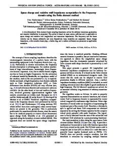
plasma spot size with a radius of 5 �m, within a cone of 1 , corresponding to a divergence of below 20 mrad.2 One experiment (see Table I) used collimation and found N � 5 � 108 electrons of 7 � 3 MeV within a cone of 5 mrad (corresponding to a �0 of 2.5 mrad) out of the original N � 2:6 � 1011 [2]. In an intuitive way it is understandable that the laserdriven electron source has low emittance to begin with, as the laser is focused to a small spot and electrons are promptly accelerated to relativistic energies while their charge is neutralized in the plasma. This raises a great deal of interest [12] with regard to its application to a bright beam source for x-ray free electron lasers (FEL) and future linear colliders. It is still obvious in the traditional electron transport Kapchinskij-Vladimirskij (K-V) theory, however, that during the beam transport, after the electron bunches emerge from the plasma, space charge effects should blow up the emittance, but the experiments appear to indicate the contrary. For example, it has been shown repeatedly [13] that the emittance would in fact blow up rapidly due to the space charge measured in the experimental data. These calculations were based on the transverse envelope equation, without coupling to the longitudinal dynamics. We recognize that this coupling can be important. This is because in these experiments (a) the longitudinal bunch length is much shorter than that of the conventional beams; (b) the longitudinal energy spread is much larger than that of the conventional ones. These two characteristics of laser-driven sources make the bunch length change rapidly as soon as the beam emerges out of the plasma wave, in particular, at low relativistic energies (a few MeV) when the space charge forces should be largest. This bunch lengthening dilutes the space charge force and thus has a sensitive influence on the transverse space charge effects. On the other hand, the increase in transverse beam spread can also mitigate the longitudinal bunch lengthening, as it too reduces the space charge effects. It is, therefore, crucial to incorporate the coupling between the longitudinal and transverse dynamics in order to evaluate the property of the laser-driven bunches and to control and utilize this potentially important new technology in high energy accelerators. As a sneak preview we show in Fig. 1 the difference between the coupled and the uncoupled calculation for data consistent with [2]. Precise definitions of concepts and parameters follow later in the text. But we should mention here that we assume the experimental data mean a uniform longitudinal distribution of the charge (FWHM) with a bunch length equal to the length of the 2 It should be noted that in general it is not known with good precision how many electrons with a determined energy are in a certain cone, with the exception of the collimation experiment [2]. Neither is the bunch length of the emerging beam known from direct measurements.
024201-2
PRST-AB 6
ALEXANDER W. CHAO et al.
024201 (2003)
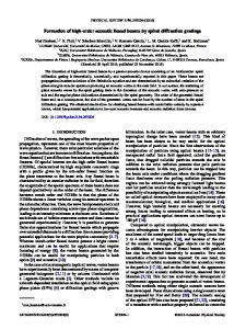
FIG. 1. (Color) Calculated longitudinal and transverse phase space evolution for coupled (thick line) and uncoupled (thin line) theory. The parameters were taken from [1,2] with� p�������������� 10 2 . All parameters are shown vs the drift length s (in �m): (a) h� i�s�, charge of N � 1p� 10 �������������� (b) hz�i�s�, (c) hz2 i�s�, (d) ��s�, and (e),(f) �0 �s�. The sixth figure (f) is the same �0 of the fifth (e), except that (f) is plotted for a shorter range in s to emphasize the initial short range development. Initial condition for � is � �0� � 5 �m, as taken from the typical size of the laser-plasma channel. We assume �0 �0� � 0, i.e., there is a beam waist at the plasma exit; calculations with �0 �0� significantly different from 0 do not match the experimental findings. All units for z, �, and s are in microns, units of divergence �0 �s� are in radian, the unit for energy related parameters is . For initial ‘‘intrinsic’’ emittance �0 we choose 0.01 mm mrad (geometric emittance) because this was the largest emittance we could use and still reproduce the experimental results with our theory, see Fig. 3, although the experiments are also reproduced with smaller emittances. Note that the drift is plotted out to 20 cm to match the experimental setup of [1], and that acceleration has not been used.
ingoing laser bunch. This distribution we convert into a parabolic distribution (analog to the transverse K-V distribution) while keeping the rms value constant. The difference between the coupled and the uncoupled case for the energy of the experiment and the �0 chosen is most pronounced, beneficial, and immediate for the longitudinal part, but Fig. 1 shows that the asymptotic �0 is lower in the coupled case as well. Since much of the emittance growth in low energy electron transport is due to growth in the energy spread, reducing this growth might be important. 024201-3
In the above discussions of space charge effects, we have ignored the influence of the plasma and the laser, assuming that the beam has emerged cleanly from the plasma and that the laser has sufficiently diverged. We can, therefore, concentrate on the dynamics of a naked space charge dominated beam in free space. In terms of the application of the laser-driven beams to an injector such as an rf accelerator, it is important to understand whether the rapid dynamical changes still allow us to properly inject the bunches into the rf accelerator structure and how to do so in practice. Since 024201-3
PRST-AB 6
SPACE CHARGE DYNAMICS OF BRIGHT ELECTRON BEAMS
the longitudinal bunch lengthening happens quickly, one has to capture the beam with rf before it becomes too long. Since the transverse beam spread takes place rapidly as well, one needs to focus the beam with a magnetic field, particularly to control the apparent emittance growth due to chromatic effects associated with the large initial energy spread [14]. In what follows, we investigate the self-consistent coupling of the longitudinal and transverse dynamics under the influence of strong space charge forces. In order to accomplish this, we first introduce an exact equilibrium distribution to the longitudinal Vlasov equation, analogous to the K-V distribution in the treatment of the transverse dynamics [15]. The longitudinal dynamics is analyzed based on this distribution, yielding a longitudinal envelope equation. An exact solution has been obtained assuming there is no rf field and assuming the coupling to transverse dynamics is ignored, while numerical solutions are presented without these assumptions. The familiar transverse dynamics with the K-V distribution is then introduced, and these two dynamics are coupled self-consistently in our treatment. In this formalism we allow an rf field as well as a solenoidal magnetic field. In Sec. II we analyze the longitudinal dynamics with respect to a reference particle. The selfconsistent longitudinal Vlasov description and the longitudinal envelope equation based on it are introduced in Sec. III. In Sec. IV we solve the longitudinal envelope equation exactly in the absence of the rf field and transverse-longitudinal coupling. The coupled transverse and longitudinal envelope equations are derived and solved numerically in Sec. V. An analysis of sample parameters deduced from plasma experiments (and hoped-for experiments) is presented in Sec. VI. We conclude in Sec. VII as to how this laser-driven plasma source may be employed and its relevance to future light sources and high energy accelerators. It is self-evident that immediate acceleration (rf capture, adiabatic damping) and magnetic focusing will be beneficial to the emittance in the drifting beam. In this paper we stop short of presenting solutions to the acceleration and focusing problem. We intend to revisit these problems in the future.
II. LONGITUDINAL EQUATION OF MOTION In a general treatment, consider a beam bunch being accelerated by a traveling wave linac with phase velocity �w � 1. The beam is under the influence of its own longitudinal and transverse space charge forces. Its bunch length is much shorter than the rf wavelength and the bunch is injected close to the crest of the rf acceleration wave. We will also include a solenoidal field for transverse focusing. The case without acceleration can be obtained by setting the acceleration gradient to zero. 024201-4
024201 (2003)
We first need to define a reference particle. Consider a reference particle injected with energy E0 exactly onto the wave crest where the acceleration electric field is E. Its equation of motion is [16] z0r � 1 �
1 ; �r
P0r � �
eE 2�zr sin ; �r c �
(1)
where the subscript r refers to the reference particle, � �0 � d ds � � with s is the longitudinal coordinate of the reference particle, Pr is the longitudinal momentum, � is the rf wavelength, and zr is the longitudinal position of the reference particle measured relative to the traveling wave (zr > 0 means the reference particle is ahead of the traveling crest). The initial conditions are zr �0� � ��=4 [the sign is chosen such that P0r �0� > 0] and Er �0� � E0 � 0 mc2 . In principle, one should be able to solve Eq. (1) and obtain zr �s� and Pr �s�. We will not do so other than estimating how much does the reference particle fall behind the traveling wave crest asymptotically s ! 1 as follows: � Z1 � Z 1 ds 1 �zr js!1 � ds 1 � � 2 �r 0 0 2 r 1 m2 c4 : (2) �� � 2 0 0r 2E0 eE Of course, this phase lag must be much less than the rf wavelength. When this is satisfied, we have zr ��=4 throughout the acceleration process. From here on, we assume zr �s� and Pr �s� are known and refer the longitudinal position z of all particles to the reference particle (z > 0 means the particle is ahead of the reference particle) and no longer to the wave crest. Let �P � mc� where � � ��� �
(3)
be the momentum deviation of a particle from the reference particle at position s. For relativistic particles, � � . (Note that � is not the conventional notation of �P=P.) We consider z and � to be small, so that all equations of motion can be linearized in these variables. This requires jzj � �, and j�j � �r r . We have z0 �
1 1 � � 2 3: � �r �r r
(4)
We have kept the factor �2r here so that our analysis can also be applied to nonrelativistic cases. In the absence of space charge force, the energy equation of motion is � � eE 2��zr � z� 2�zr 0 � �� 2 � sin sin : (5) � � mc �r Away from the crest, one may linearize Eq. (5) as � � 2�eE 2�zr �0 � cos z: � mc2 �r �
(6)
024201-4
PRST-AB 6
ALEXANDER W. CHAO et al.
Near the crest, one may still use Eq. (6), which gives �0 0, provided that the phase slippage (2) can be ignored. In the following, when we consider an accelerated beam, we shall assume that the beam is near the crest and that the phase slippage is ignorable. This assumption implies that r �s� � 0 �
eE s mc2
(7)
and that �0 � 0 in the absence of the space charge force. As stated earlier, we will carry the formalism for acceleration and focusing forward as long as practical, up to Eq. (28), but we will not numerically solve the differential beam equation with it. III. LONGITUDINAL ENVELOPE EQUATION In this section, we introduce a model of longitudinal beam distribution for our space charge analysis. We assume in this section that there is no external focusing or acceleration. Extensions to include these effects, although straightforward, are not needed for our later applications. We propose as ansatz the following R Rdistribution in phase space �z; ��, normalized by dz d� � N, the number of charged particles in the bunch: s��������������������������������������������������������������������� � 2 2 �� 3N h� iz � 2hz�iz� � hz2 i�2 �z; �� � 1� ; 10�A 5A2 (8) p���������������������������������� where A � hz2 ih�2 i � hz�i2 , and h�2 i, hz�i, and hz2 i will depend on s and are the three dynamical quantities being studied. We shall examine their time evolution under the influence of longitudinal space charge force. The overall shape of the distribution is a tilted ellipse. Outside of the ellipse the distribution vanishes. The quantity A is the phase space area occupied by the beam, divided by �, and is the rms longitudinal emittance of the beam. This quantity will be conserved even as h�2 i, hz�i, and hz2 i evolve with time s, as the distribution evolves according to the Vlasov equation in our problem. This conservation law will be confirmed algebraically later. This distribution (8) for the longitudinal envelope equation will be shown to be the equivalent of the K-V distribution for the transverse envelope equation in the sense that it allows an exact analysis of the longitudinal problem in a self-consistent manner just as the K-V distribution allows exact analysis of the transverse problem. The longitudinal beam distribution is obtained by integrating �z; �� over �, ��z� �
024201-5
3N 2 �^z � z2 �; 4^z 3
jzj < z^ ;
(9)
024201 (2003)
where the half width at zero height bunch p���p�������� p��� length z^ � 5 hz2 i. Note that the exact factor of 5 is due to the parabolic form of Eq. (9). Any reasonably defined FWHM (full width half maximum) distribution follows similar laws. For a uniform longitudinal p���p�������� distribution we have a full bunch length L^ � 2 3 hz2 i. R This parabolic distribution has normalization dz��z� in Eq. (8) is such R �RN. Parametrization R R 2 2 that d� dz z � hz i, d� dz z� � hz�i, and R R d� dz �2 � h�2 i as it should. The longitudinal space charge force gives (assuming a= � z^ ) [17] � � eE �z� 2r d��z� b 1 �0 � s2 � � 02 ln � � !2 z; (10) a 2 mc �r �r r dz where E s is the longitudinal space charge electric field, a is the transverse beam size radius (assumed uniform disk, as would be the case for a K-V distribution), b is the pipe radius (assumed cylindrical and perfectly conducting), and we have defined a quantity � � 3Nr0 b 1 !2 � 3=2 � : (11) ln 5 �r 2r hz2 i3=2 a 2 Reference energy r , beam radius a, and pipe radius b are potentially functions of s. Both Eqs. (4) and (10) are linear in �z; ��. These linearity properties assure that the distribution (8) will remain elliptical and will maintain the ansatz form. The space charge force being linear in z is a consequence of the longitudinal beam distribution being parabolic. The motion is of course unstable, and all single particle trajectories are basically hyperbolic. Evolution of the distribution function is determined by the Vlasov equation @ 1 @ @ � 2 3� � !2 z � 0: @s �r r @z @�
(12)
Substituting Eq. (8) into (12), keeping in mind the fact that h�2 i, hz�i, and hz2 i are functions of s while A is a constant of the motion, we obtain 1 ��2zh�2 i � �2r 3r 2�hz�i� � !2 z��2zhz�i � 2�hz2 i� � 0:
�h�2 i0 z2 � 2hz�i0 z� � hz2 i0 �2 � �
(13) Equation (13) contains three terms, each proportional to z2 , z�, and �2 , respectively. Since Eq. (13) must be satisfied for all z and �, each of the coefficients of these three terms must vanish separately. Therefore, h�2 i0 � 2!2 hz�i;
hz�i0 � hz2 i0 �
1 �2r 3r
2 hz�i: 2 �r 3r
h�2 i � !2 hz2 i; (14)
Note that !, given by Eq. (11), depends on hz2 i and 024201-5
PRST-AB 6
SPACE CHARGE DYNAMICS OF BRIGHT ELECTRON BEAMS
therefore is a dynamical quantity. Note also that Eqs. (14) can also be obtained by observing h�2 i0 � 2h��0 i � 2h�!2 zi;
� 1 2 �h!2 z2 i; � hz�i0 � hz0 �i � hz�0 i � �2r � 3r
1 hz2 i0 � 2hzz0 i � 2 z 2 3 � : �r r
(15)
The partial differential Vlasov equation (12) is now reduced to three coupled first order ordinary differential equations (14) by the ansatz distribution (8). Equations (14) will be referred to as the longitudinal envelope equations. Equations (14) can be combined to give �hz2 ih�2 i � hz�i2 �0 � 0, which means A � const of the motion and is determined by the initial conditions of the beam. As the Vlasov equation conserves the phase space volume, and since our beam has started out as an ellipse and remained an ellipse, this conservation is reasonable and expected. However, the issue of emittance preservation, or its blowup, is a subtle and important question. To begin with, a real system of particle beams is composed of individual particles which can be represented by delta functions in phase space. This distribution is called the Klimontovich distribution. The result of averaging the Klimontovich distribution is the Vlasov distribution. The former distribution obeys the Klimontovich equation [18], whose operational form ‘‘appears’’ to be identical to the Vlasov equation before one does smoothing and averaging. These two should not be confused, because the averaged Klimontovich equation no longer appears the same as the Vlasov equation. Because of microscopic mixing, the entropy (and emittance) in the Klimontovich system can increase [19]. This first cause of emittance increase is intrinsically due to a ‘‘collisional’’ (of either single particle nature or collective nature) effect. Particle-in-cell simulations such as PARMELA [20] follow individual particle dynamics along with their self-consistent fields, which make up the Klimontovich system. In addition to this distinction between the Klimontovich’s and Vlasov’s phase space behavioral differences, there are other causes of emittance increase, even within the Vlasov system. When there are nonlinear interactions in the Vlasov system, i.e., due to an energy spread, these can give rise to contorted fine-structured phase space shape of the beam. Even though the Vlasov equation guarantees that the phase space volume of this contorted beam is unchanged, the smooth envelope of this contorted distribution may be greater than the original phase space occupation. This is the second cause of emittance increase due to the nonlinearity. A third possible emittance increase is due to the projection of higher dimensional emittance (say 6D) onto subspace (say 2D). Even though the 6D phase space 024201-6
024201 (2003)
volume may be constant, the envelope of this projected 2D volume may become greater. The emittance increases due to a dependence of the 2D dynamics on some external parameters, such as a particle’s energy. This parametric emittance growth can be recovered by appropriately compensating the parametric dependence. In this article, we are looking only at this last level of emittance increase, if any. The choice of ellipse and lack of nonlinearity of our analytical distribution allow us to have emittance preserved as we have seen in the constancy of A above. Given initial values h�2 i�0�, hz�i�0�, and hz2 i�0� and the prescribed a�s�; b�s� and r �s�, our task is then to solve for the time evolution of h�2 i�s�, hz�i�s�, and hz2 i�s� using Eq. (14). IV. THE CASE WITHOUT ACCELERATION AND WITHOUT COUPLING TO TRANSVERSE DYNAMICS When there is no acceleration, all results in the previous sections still apply by setting E � 0. Appropriate factors of �r have been kept so that the previous analysis, particularly Eqs. (14), also applies to the nonrelativistic case. Without acceleration, �r and r are constants. In the remainder of this section, we assume the transverse beam size a and the pipe size b are also constants in s, or at least if the pipe size is made to scale with the beam size. In this case, we can solve Eqs. (14) analytically as follows. Transform the quantities from h�2 i, hz�i, hz2 i, and s to dimensionless u; v; w, and t, where h�2 i � �4r 4r u;
hz�i � �2r 2r �v;
hz2 i � �2 w;
t�
s ; r � (16)
and where ��
3Nr0 �lnba � 12� : 53=2 �3r 3r
(17)
Equations (14) then become du 2v � ; dt w3=2
dv 1 � u � 1=2 ; dt w
dw � 2v: dt
(18)
Given initial conditions u�0�, v�0�, and w�0�, Eqs. (18) can be solved for v�t� to yield p��������������� � � 1 v � v2 � C p��������������������� ; (19) u1 t � v � v�0� � p������� ln u1 v�0� � v2 �0� � C where we have defined 2 u1 � u�0� � p���������� ; w�0�
(20)
024201-6
PRST-AB 6
ALEXANDER W. CHAO et al.
1 C � u�0�w�0� � � v2 �0�: u1
(21)
Once v�t� is obtained from Eq. (19), w�t� and u�t� are found by 1 p�������p��������������� w � 2 �1 � u1 v2 � C�2 ; (22) u1 2 u � u1 � p���� : w
(23)
As t ! 1, the asymptotic behavior is such that h�2 i ! const, i.e., the beam energy spread saturates and reaches a plateau. This is because as the beam bunch lengthens, the space charge force weakens, and the beam energy spread saturates. Beyond that point, the bunch lengthens linearly with time and one expects hz2 i to be quadratic in time and hz�i to be linear in time. The quantity u1 is the saturation value of u. The asymptotic expressions are u ! u1 ;
v ! u1 t;
w ! u1 t2 ;
(24)
size � is given by � � 12 a. Normalization is R dxdpx dydpy � e�. We also define normalized emittance by �N � �r r � and �N;rms � �r r �rms . Including the effects of transverse focusing by a solenoidal field Bs and a constant acceleration �� �0 � *, the transverse envelope equation is given by [15,17] A00 � KA �
p����������� A � a �r r ; -�
K�
�
(28)
4r0 �d ; �2r 3r
eBs 2mc2 r
�2
�
(29) (30)
*2 : 4�2r 2r
(31)
At the center of the longitudinal bunch distribution (9), the line charge density is �d �
2�4 4 � h�2 i�s ! 1� � h�2 i�0� � 2 r1=2r ; hz i �0� s 2 hz�i�s ! 1� � 2 3 h� i�s ! 1�; �r r s2 2 hz i�s ! 1� � 4 6 h�2 i�s ! 1�: �r r
�2N �r r ; � 2A A3
where
or, in terms of the physical quantities,
3N 3N � p��� 2 1=2 : 4^z 4 5 hz i
(32)
This gives (25)
The distance S the beam has to travel before its bunch length doubles and energy spread approaches saturation can be estimated by s���������� w�0� 2�2r 3r hz2 i1=2 �0� � : (26) T�2 or S � q���������������������������������� 4 4 u1 h�2 i�0� � 2�r r � hz2 i1=2 �0�
V. COUPLED TRANSVERSE AND LONGITUDINAL ENVELOPE EQUATIONS So far we have ignored the transverse dynamics. If we assume the transverse beam distribution is that of a K-V distribution, the transverse dynamics can be described by a transverse envelope equation. In our study, we consider a round beam. The K-V distribution in the transverse phase space is � 2 � e� x � y2 a2 �p2x � p2y � �x; px ; y; py � � 2 2 � � �1 ; �� �2 a2 (27) where ��x� is the delta function, and � is the total unnormalized transverse emittance of the beam. The rms emittance is given by �rms;x � �rms;y � 14 �. The rms beam 024201-7
024201 (2003)
3Nr - � p��� 2 3 0 2 1=2 : 5�r r hz i
(33)
Note that by taking for �d its peak value, i.e., at the bunch center, we are considering the dynamics of a central slice of the beam, a choice which will somewhat overestimate the space charge effect for the whole beam bunch. Once Eq. (28) is solved forpA, the� rms transverse beam ���������� size is given by � � A=�2 �r r �. In the absence of acceleration and solenoidal field, Eq. (28) becomes �00 �
�2N;rms : � �2r 2r �3 8�
(34)
Coupling of transverse dynamics to the longitudinal dynamics is contained in the parameter -. To see the coupling of longitudinal dynamics to the transverse dynamics, we go back to Eqs. (14). The longitudinal envelope equation in free space is still given by Eqs. (14), except that this time !2 of Eq. (11) is rewritten as �� � � �p��������������������������� 3Nr0 1 1 2r hz2 i � 4�2 2 ln � : (35) ! � 3=2 2 2� 5 �r 2r hz2 i3=2 Coupling of longitudinal dynamics to the transverse dynamics is described by the relatively weak dependence of � in the logarithmic term in !2 . In Eq. (35), the vacuum chamber pipe radius b has been taken to be p������������������������ � 2r hz2 i � a2 because we assume the beam is propagating in free space without a pipe, to reflect the actual 024201-7
PRST-AB 6
SPACE CHARGE DYNAMICS OF BRIGHT ELECTRON BEAMS
experimental setup. If there is a metallic beam pipe, then we should keep b and not make this replacement. Equations (14) and (28) are coupled envelope equations for round beams. The longitudinal and transverse emit� p��������������������������������� tances h�2 ihz2 i � hz�i2 and �rms are constants of the motion even with the coupling. It should be emphasized that there is no intrinsic emittance growth in the present model, as mentioned earlier due to the Vlasov dynamics. Any apparent emittance growths will have to result from nonlinearities in the space charge force or the nonlinear kinematics in free space, neither of which are included in the present analysis. Such apparent emittance growth refers to the rms value and does not violate the Liouville theorem. It is instructive to solve Eq. (34) in an iterative fashion. As is clear from Fig. 1, the growth of �0 � d�=ds appears to saturate in time. After its initial rapid increase the asymptotic behavior of �0 is dictated by the term on the right-hand side of Eq. (34) only. A closer look at its asymptotic behavior indicates that �0 slowly increases in s as a function of the square root of a logarithm of s. Since the logarithmic dependence is weak, we can iteratively solve this by integrating over s to yield s���������������������� s���������������������� � p��� �� � p��� �� s s 1 s �1 - ln - ln ; �01 ; (36) 2 2�0 2 2�0 where the subscripts 1 refer to the quantities evaluated at the position of the measurement. An estimate of an apparent exit emittance, �01 , is therefore �20 ; (37) ��p q������������������������������������������������������ p���� p��� where G � 3 ln��s -�=�2�0 ��=16� 5 is a numerical quantity nearly equal to unity, �p � c=!p is the collisionless skin� depth of the source plasma, and !p � p ������������������������� 4�ne2 =m 3 is the longitudinal plasma frequency of the emerging beam with Lorentz factor and beam electron density n � N=�20 �z0 . Equation (37) indicates that the beta function at the plasma source is given by the plasma collisionless skin depth �p times �. The smaller the laser spot size, the smaller the values of �01 ( / �20 ). The greater the skin depth, either by a lower plasma density or by higher electron energy, the smaller the value of �01 . Note, as before, that the apparent emittance �01 is not to be confused with the actual beam emittance at either the source or the position of measurement. Nevertheless, �01 is a quantity which impacts on the results of our calculations. In turn this makes it an experimentally accessible quantity useful to compare with experimental observations through Eq. (34) without acceleration and focusing, and Eq. (28) in the general case. Since nearly all SMLWFA experiments operate with laser channels in the 5–8 �m radius range, it might not be �01 � �0 � �01 � G
024201-8
024201 (2003)
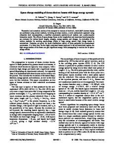
surprising that all our results are compatible with �0 0:01 mm mrad (or lower, something we cannot test with just analyzing the divergence). VI. APPLICATION TO PLASMA BEAM SOURCES In this section, we will apply the analysis to a sample set of parameters, as shown in Table I. In this example application, there is no solenoidal field and the electron motion is relativistic. The first group of numbers in Table I are input numbers. The second group are derived ones. The third group applies only if transverse-longitudinal coupling is ignored. If we ignore the transverse-longitudinal p���������������������������� coupling, we may replace the quantity 2r hz2 i � 4�2 in Eq. (35) � p��������������������������������������� 2 2 2 by r hz i�0� � 4� �0� and replace hz2 i in Eq. (33) somewhat arbitrarily by hz2 i�0�. Under these approximations, the bunch length doubles and the energy spread approaches saturation in about a distance S, and the asymptotic energy spread is h�2 i�s ! 1� � �4r 4r u1 . Values of these quantities in the absence of transverse-longitudinal coupling have been listed in Table I. It must be emphasized that ignoring the coupling, as is customary, requires the choice of arbitrarily fixed longitudinal and transverse parameters. If we retain the transverse-longitudinal coupling, as we should, we must apply Eqs. (14) and (28) and solve them numerically. Our calculations here are based on experimental results of Refs. [1,2,4]. Parameters collected in Table I are based on a reasonable interpretation and interpolation of the results. In what follows, we assume there is no acceleration. We have tested the effect of an acceleration of 100 MeV=m on the longitudinal phase space (not shown here): it basically stops both the bunch lengthening and the energy spread increase. The exact value of the acceleration gradient was not critical, but was a good indication of the effect of capturing by rf acceleration and adiabatic damping. Earlier we compared in Fig. 1 some parameters for the coupled and uncoupled cases for a charge of N � 1 � 1010 (1.7 nC). The thin curves were the results when transverse-longitudinal coupling is ignored. Now in Fig. 2 we compare three different charges N � 0, N � 5 � 108 , and N � 1 � 1010 extracted from the experiments, all with coupling. We see that (i) by comparing the two curves in Fig. 1 the transverse-longitudinal coupling is significant with N � 1010 and affects the longitudinal dynamics more than it affects the transverse dynamics. (ii) By comparing Figs. 1 and 2 at 7 MeV the transverse space charge force has a large effect on the divergence, while the effect of the longitudinal space charge force on the energy spread is relatively small even for N � 1 � 1010 , very small when N � 5 � 108 , and zero for N � 0. (iii) The bunch length grows even without a charge due to the velocity spread at the beginning. (iv) By comparing the three 024201-8
PRST-AB 6
ALEXANDER W. CHAO et al.
024201 (2003)
FIG. 2. (Color) Calculated longitudinal and transverse phase space evolution for three different charges N � 0, N � 5 � 108 , and N � 1 � 1010 , respectively, in the order of the lines shown, all for an assumed bunch length (FWHM) of 120 �m. The latter two charges are within the range reported from the experiments [1,2,4], and N � 5 � 108 is precisely the value reported in [2] for the collimated beam with collimation angle �2:5 mrad.� Shown are, p�������������� as in Fig. 1,� the phase space parameters vs the drift lengths (in �m): (a) h�2 i�s�, (b) hz�i�s�, p������������� (c) hz2 i�s�, (d) ��s�, and (e),(f) �0 �s�. The sixth figure (f) is the same �0 of the fifth (e), except that it is plotted for a shorter range in s to emphasize the initial short range development. The calculations were extended to a length of 2 m, because the experiment [2] collimated and measured the beam at this distance. Initial condition for � is � �0� � 8:5 �m, the radius of the laser-plasma channel in this case [2]. Assumption of �0 �0� � 0 was found to be compatible for agreement between calculations and experiments, �0 �0� � 0 was not. All units for z, �, and s are in microns, divergences �0 �s� are given in radian. And finally, assuming �0 � 0:01 mm mrad seems to be in better agreement with the experiment than a substantially larger value, while a substantially smaller value had no effect on the calculation (see Fig. 3).
curves in Fig. 2, the longitudinal space charge forces have some effect on the energy spread and the transverse space charge forces have a strong effect on the divergence when N � 1010 . The analysis can also be applied to proton beams emerging from a plasma source [21]. The kinematics are derived in such a way that the analysis still applies when the beam is nonrelativistic. In this case, we go back to Eq. (1) and choose the wave velocity and the reference particle velocity in such a way that �w � �r . Then Eq. (7) and the numerical scheme still apply. 024201-9
VII. CONCLUSION AND DISCUSSION We have carried out an investigation of the effects of space charge on bright electron beam sources. In particular we are interested in understanding the series of recent experiments in which laser-driven electron beams are generated in a plasma medium with evidence that these beams may possess interesting properties including an emittance perhaps an order of magnitude lower than the rf-based electron beam sources. It may defy our intuition that space charge effects did not degrade the emittance in 024201-9
PRST-AB 6
SPACE CHARGE DYNAMICS OF BRIGHT ELECTRON BEAMS
these cases. In order to understand this, we have developed an analysis of the longitudinal dynamics based on a model that allows the development of a longitudinal envelope equation. The model assumes a phase space distribution which, when projected onto the longitudinal coordinate space, results in the parabolic form of Eq. (9). Its role in longitudinal dynamics is similar to the role played by the K-V distribution in transverse dynamics. Analytic as well as numerical characterization of this longitudinal dynamics has been derived. We have further developed a theory of coupled longitudinal and transverse dynamics, in which the transverse dynamics is based on the exact treatment of the K-V distribution. It is this coupled equation that indicates an important mitigating effect of space charge on the transverse emittance increase during the early phase of the beam dynamics shortly after the beam emergence from the source. The relatively large energy spread characteristic of the laser experiments based on the mechanism of the SMLWFA causes a rapid longitudinal beam lengthening, which dilutes the space charge effects and in turn reduces the increase of transverse emittance (or more precisely, the transverse beam divergence). The prompt acceleration of electrons in the laser source to relativistic energies (beyond � 10) also helps in reducing this emittance increase. One of the experiments [2] measured quantities that may be related to the emittance of the beam. For this reason, we have singled it out for our analysis, though this experiment may benefit from additional more definitive measurements and also other experiments may hold similar parameters. For now, for lack of better or more definitive measurements, we take this experimental observation at face value. The experiment showed a surprisingly small apparent emittance �01 � �0 �01 [as defined in Eq. (37)] with 5 � 108 electrons, in the ball park of 0.01 mm mrad, an order of magnitude smaller than a typical high-performance rf source. Our theory described above helps in determining the emittance �0 at the plasma exit at, or less than, 0.01 mm mrad for the same parameter regime. Without the longitudinal-transverse coupling, the transverse apparent emittance (or more precisely the beam divergence) would rise quicker. In this way, our theory provides a possible avenue of understanding the experimental findings. A more complete analysis should include the nonlinear effects of more realistic distributions. Note that the currently adopted distribution does not have nonlinearities by its very nature. We have begun investigating the development of the intrinsic emittance using a 2.5 dimensional particle acceleration code, PARMELA [20]. So far our starting distribution is flat in the configuration space density. The code can also follow nonlinearity as well as individual particle effects; in our operational regime, the former is more important. In these first PARMELA runs we observe that the transverse beam size and the angular 024201-10
024201 (2003)
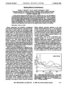
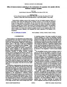
divergence are in good agreement with the experimentally derived values described in the previous Sec. VI. It means that as far as the quantity �01;rms � �0 �01 is concerned, the experimentally derived quantity and the PARMELA result both can be understood with our theory, thus supporting the possibility that the (intrinsic) emittance at the plasma exit is �0 � 0:01 mm mrad or possibly even smaller at the source, as indicated by the results shown in Fig. 3. We have a preliminary finding from PARMELA , however, that the emittance increase continues even after the angular divergence �0 saturates, when the space charge effect is sufficiently diluted in the expanding beam. The origin of this emittance increase is the dependence of the transverse dynamics (with and without the space charge force) on particle energy (/1= 3 ), together with a large energy spread of the beam. Because of this nonlinearity, low energy beam particles rotate faster than more energetic ones in the phase space of x-x0 , giving rise to the socalled bow-tie diagram. The above analysis has ignored one unique aspect of plasma-generated bright electron beams, i.e., its substructure of femtosecond length bunches. Ignoring the substructure was justified here because the observed rapid bunch lengthening of SMLWFA produced bunches will wash out the bunching, before rf acceleration. Nevertheless it is appropriate to investigate sub-bunched beams in the framework presented here because of the following reason. As mentioned before, a new type of laser wake field acceleration using two or more lasers, beyond the self-modulated case, has been investigated in simulations [9–11]. These simulations calculate expressively the charge, bunch length, and emittance for one fstype sub-bunch. These beams are predicted to have a very small energy spread so they may behave differently from the broad energy spectrum of the SMLWFA. First experimental results are just forthcoming [22]. The basic idea is to give the electrons an additional push to be trapped in the plasma wave [9–11]. The numerical simulations from [23] result in a charge per plasma bucket between N � 2:5 � 106 and N � 1:5 � 107 , depending on the size of the laser focus. The electron bunch length is 1 fsec, in the plasma wave bucket of a few fsec. Reference [23] calculates an energy of 40 MeV at the plasma exit and an energy spread of 80 keV. Simulations by others [9–11] show similar results. Figure 4 shows the longitudinal and transverse phase space development for three values of charge, using the formalism of this paper. The longitudinal phase space is noticeably impacted, while the impact on the transverse phase space is minor. If one keeps the charge constant and changes the initial emittance by an order of magnitude, the role of transverse and longitudinal phase space is reversed. The total charge of O�nC� needed for some applications is thought to be created by using many plasma buckets. If further studies 024201-10
PRST-AB 6
ALEXANDER W. CHAO et al.
024201 (2003)
Divergence σ1′ after 2 m Drift as a Function of Plasma Exit Emittance ε0 100
←Best RFGun
Divergence [mrad]
1 x 10¹⁰ e
10
← σ’ measured at 20 cm, 10
e
10
bunch length=120 µ m 0.05 x 10¹⁰ e
⇐ bunch length=175 µ m 8
← σ’ collimated at 2 m, 5 x 10 e
10
0 x 10 1
0.001
.01
e
Geometric Emittance ε0 [mm mrad]
.1
FIG. 3. (Color) Calculated divergence after 200 cm drift for charges N � 0 (green), N � 5 � 108 (red), and N � 10 � 1010 (blue) at an energy of 7 � 3 MeV as a function of the plasma exit emittance �0 . This calculation assumes a 400 fsec long laser pulse (FWHM, 121 �m) creating a 8:5 �m radius plasma channel. Below an emittance of 10�8 mrad the dependence is flat. That is to, say, that even if �0 would be smaller than 0.01 mm mrad (which is possible, but which we can neither prove nor disprove), it would have no impact on the divergence. In turn, the divergence at the high charge case, the observed beam divergence of 17 mrad [1,4] does not allow to conclude, nor does it refute, that the emittance is smaller than 0.01 mm mrad; in this sense the measurements establish an upper bound on �0 . Since the N � 5 � 108 case was due to collimation, the initial beam of 2:6 � 1011 did undergo more rapid expansion. We do not find a self-consistent solution with a bunch length equal to the laser bunch length, a length of 175 �m gives better agreement. And finally, �0 � 0:01 mm mrad seems to be in better agreement with the experiments than a substantially larger value. These are not universal curves; they depend on the parameters used.
hold that in fact these electron sources driven by multiple lasers can provide a large number of electrons (> 5 � 108 , up to 1010 ) with normalized rms transverse emittance of 0.1–0.01 mm mrad, their application to the future x-ray light sources such as LCLS and beam sources for future linear colliders is promising. Ironically enough, in contrast to classical (photo) cathode guns, the problem of plasma guns might be in producing too short a bunch, with too high a charge. However, longer laser pulses with enough power are in the realm of the possible. For future linear colliders [24 –26], in addition to the cases already shown, we might consider a long beam case: N 1010 , �x;N � �y;N 10�7 mrad, and z�FWHM� � 730 �m. We further assume that after 2 cm of drift we would be able to capture the beam in an rf acceleration field (rf capture, adiabatic damping). Using PARMELA simulations we have found that for a bunch with 024201-11
an initial FWHM length of 730 �m (10 X band), N � 1010 e� , �0;rms � 1 � 10�8 mrad, and energy of 7 � 3 MeV, after the 2 cm drift the emittance grows to 3 � 10�8 mrad (44 � 10�8 mrad normalized). If we reduce the charge to 1 nC (0.624 1010 e� ), for comparison to the ‘‘standard’’ charge quoted for rf guns, we find for the same parameters that the normalized emittance after 2 cm drift is 32 � 10�8 mrad, a factor of 4 improvement from what is expected from conventional rf guns. One should be aware of the asymmetric emittance requirements of linear colliders, where �Nx � 3 � 10�6 mrad, but �Ny � 3 � 10�8 mrad. Figure 5 shows that by stretching the beam, the space charge effect on the energy spread is mitigated (note the suppressed zeros in some graphs) so that the low emittance at the source can be maintained during drift. We note that such a beam source may be attractive for future collider applications. 024201-11
PRST-AB 6
SPACE CHARGE DYNAMICS OF BRIGHT ELECTRON BEAMS
024201 (2003)
FIG. 4. (Color) Longitudinal and transverse phase space dynamics for an example of bunches produced by ‘‘colliding’’ lasers [23] for three charges of 0, 0.43, and 2.53 pC per micro (plasma) bucket. The curves are calculated for general electron bunch parameters of E0 � 40 MeV, �E � 80 keV, bunch length 2 � 1 fsec (0:3 �m) per 3 fsec plasma bucket, and initial divergence �0 �0� � 0. For ease of comparison we used an initial spot size of ��0� � 5 �m, although the simulations had to use a larger ��0� � 15 �m for the ‘‘high’’ charge case to get sufficient charge. The curves are for charges of 0, 0.43, and 2.53 pC, respectively, and show marked differences only for the longitudinal phase space. Because of the detrimental effect of energy spread on the emittance early rf capture might be important for a practical injector.
On the other hand, the beam source requirements for x-ray free electron lasers are different. It prefers a shorter bunch length, while the transverse emittance requirement in the vertical can be relaxed since beams have to be round. The present requirements for a coherent light � region are �Nx � �Ny 10�6 mrad source in the 1–2 A [27]. In this case, we could use a beam source with a long laser, followed by bunch compression if necessary, or we might adopt even higher plasma density with a shorter laser pulse length, while still using the SMLWFA scheme. Under either scenario, with a normalized emittance in the 10�7 mrad range the FEL saturation gain length can be substantially reduced by a factor of a few [28]. This is primarily due to the higher beam density achievable 024201-12
by laser-driven beam sources over the more conven� tional methods. In any case, to go beyond the 1 A � limit to 0:1 A one needs an emittance of �Nx � �Ny 10�7 mrad [29]. In conclusion, we have shed light on some of the puzzling aspects of space charge effects associated with the laser-driven bright beam sources by analytically solving the longitudinal dynamics and its coupling to the transverse dynamics when the space charge effects are severe. If the size and angular spread of the laser-driven beam sources can properly be used with further studies, these beam sources may portend a promising exploration of a new kind of bright sources for the applications to future colliders and x-ray light sources. 024201-12
PRST-AB 6
ALEXANDER W. CHAO et al.
024201 (2003)
FIG. 5. (Color) The curves show that with a pulse length of 2400 fsec (730 �m � 10 X band) a regime has been reached, which is very insensitive to charges of 1 nC and below. The curves are calculated for general electron bunch parameters of E0 � 7 MeV, �E � 3 MeV, bunch length 2 � 3000 fsec (1000 �m), an initial spot size of ��0� � 5 �m, initial emittance 0.01 mm mrad, and initial divergence �0 �0� � 0. The two curves are for charges of 0.1 and 0.624 1010 e� , respectively, and show that the impact of the space charge forces on such long pulses is minor (note the suppressed zeros for the longitudinal graphs), even so the differences in � and �0 for the two different charges are considerable.
ACKNOWLEDGMENTS We thank Eric Colby, Gerry Dugan, Eric Esarey, Heinz-Dieter Nuhn, Ron Ruth, Carl Schroeder, and Don Umstadter for stimulating discussions and constructive criticism. This work was supported by the Department of Energy, Contract No. DE-AC03-76SF00515. Note added in proof.—When we were ready to publish, we learned that Gerry Dugan from Cornell, with LBL collaborators, was working on the same topic, but using a different approach: 6-dimensional elliptical distributions. The Cornell-LBL work will be reported on at the 10th Advanced Accelerator Concepts Workshop 2002, Oxnard, California, as will be this paper. Gerry kindly ran our examples with his code, which showed that the two models agreed well when the proper scalings and approximations were used. 024201-13
*Present address: Advanced Photon Research Center, Japan Atomic Energy Research Institute, Kizu-cho, Kyoto 619-0215, Japan. [1] S. Y. Chen, M. Krishan, A. Maksimchuk, R. Wagner, and D. Umstadter, Phys. Plasmas 6, 4739 (1999). [2] K. A. Assamagan, W.W. Buck, S.-Y. Chen, R. Ent, R. N. Green, P. Gueye, C. Keppel, G. Mourou, D. Umstadter, and R. Wagner, Nucl. Instrum. Methods Phys. Res., Sect. A 438, 265 (1999). [3] R. Kodama, K. A. Tanaka, Y. Sentoku, T. Matsushita, K. Takahashi, H. Fujita, Y. Kitagawa, Y. Kato, T. Yamanaka, and K. Mima, Phys. Rev. Lett. 84, 674 (2000). [4] W. P. Leemans, D. Rodgers, P. E. Catravas, C. G. R. Geddes, G. Fubiani, E. Esarey, B. A. Shadwick, R. Donahue, and A. Smith, Phys. Plasmas 8, 2510 (2001). [5] V. Malka, J. Faure, J. R. Marues, F. Amiranoff, J. P. Rousseau, S. Ranc, J. P. Chambaret, Z. Naimudin,
024201-13
PRST-AB 6
[6] [7]
[8]
[9] [10] [11] [12]
[13]
[14]
SPACE CHARGE DYNAMICS OF BRIGHT ELECTRON BEAMS
B. Walton, P. Mora, and A. Solodov, Phys. Plasmas 8, 2605 (2001). T. Tajima and J. M. Dawson, Phys. Rev. Lett. 43, 267 (1979). K. Nakajima, D. Fisher, T. Kawakubo, H. Nakanishi, A. Ogata, Y. Kato, Y. Kitagawa, R. Kodama, K. Mima, H. Shiraga, K. Suzuki, K. Yamakawa, T. Zhang, Y. Sakawa, T. Shoji, Y. Nishida, N. Yugami, M. Downer, and T. Tajima, Phys. Rev. Lett. 74, 4428 (1995). A. Modena, Z. Najmudin, A. E. Dangor, C. E. Clayton, K. A. Marsh, C. Joshi, V. Malka, C. B. Darrow, C. Danson, D. Neely, and F. N. Walsh, Nature (London) 377, 606 (1995). D. Umstadter, J. K. Kim, and E. Dodd, Phys. Rev. Lett. 76, 2073 (1996). B. Rau, T. Tajima, and H. Hojo, Phys. Rev. Lett. 78, 3310 (1997). E. Esarey, R. F. Hubbard, W. P. Leemans, A. Ting, and P. Sprangle, Phys. Rev. Lett. 79, 2682 (1997). R. Pitthan, in Proceedings of the SLAC Seminar, 2001, http://www-project.slac.stanford.edu/lc/local/xfel/ PlasmaGunSLACJan_11_01.pdf; in Proceedings of the Linear Collider Workshop, 2002, SLAC, http:// www- conf.slac.stanford. edu/ lc02 / wg1/ WG1_Pitthan_ 0207.pdf Y. Batygin (private communication); K. Flo¨ttmann (private communication); V. Telnov (private communication). D. Yeremian, in Proceedings of the Linear Collider Workshop, 2002, SLAC, http://www-conf.slac. stanford.edu/lc02/wg1/WG1_Yeremian_0207.pdf
024201-14
024201 (2003)
[15] I. M. Kapchinskij and V.V. Vladimirskij, in Proceedings of the 2nd International Conference on High Energy Accelerators and Instruments (CERN, Geneva, 1959), p. 274. [16] Georges Doˆme, ‘‘Electron Bunching by Uniform Sections of Disk-Loaded Waveguide, Part A: General Study’’, M-242-A, 1960, W.W. Hansen Lab, Stanford University. [17] A.W. Chao, Physics of Collective Beam Instabilities in High Energy Accelerators (Wiley, New York, 1993). [18] Yu. L. Klimontovich, Sov. Phys. JETP 11, 117 (1960). [19] S. Ichimaru, Basic Principles of Plasma Physics: A Statistical Approach (Addison-Wesley, Reading, 1973). [20] H. S. Deaven and K. C. D. Chan, Computer Codes for Particle Accelerator Design and Analysis: A Compendium, Report No. LA-UR-90-1766, 1990, p. 137. [21] A. Maksimchuk, S. Gu, K. Flippo, and D. Umstadter, Phys. Rev. Lett. 84, 4108 (2000), and references therein. [22] D. Umstadter, in Proceedings of the SLAC Seminar, 2001, http://www.slac.stanford.edu/grp/ara/meetings/ seminar/archive2001/trans/nov01.pdf [23] C. B. Schroeder, P. B. Lee, J. S. Wurtele, E. Esarey, and W. P. Leemans, Phys. Rev. E 59, 6037 (1999). [24] C. Adolphsen et al., SLAC Report No. 474, 1996. [25] N. Akasaka et al., KEK Report No. 97-1, 1997. [26] F. Richard et al., DESY Report No. 2001-11, 2001. [27] The LCLS Design Study Group, SLAC Report No. SLAC-R-521, 1998. [28] H. D. Nuhn (private communication). [29] J. Rossbach, E. L. Saldin, E. A. Schneidmiller, and M.V. Yurkov, Nucl. Instrum. Methods Phys. Res., Sect. A 374, 401 (1996).
024201-14