26th International Symposium on Automation and Robotics in Construction (ISARC 2009)
Sparse Reconstruction and Geo-Registration of Site Photographs for As-Built Construction Representation and Automatic Progress Data Collection Mani Golparvar-Fard1, Feniosky Peña-Mora2 and Silvio Savarese3 William E. O’Neil Pre-Doctoral Candidate in Construction Management and Master of Computer Science Student, University of Illinois, Urbana-Champaign, 205 N. Mathews Ave., Urbana, IL 61801; PH (217) 3332071; FAX (217) 265-8039; email:
[email protected] 2 E.W. and J.M. Gutgsell Endowed Professor in Construction Management and Information Technology, Civil and Environmental Engineering, University of Illinois, Urbana-Champaign, 205 N. Mathews Ave., Urbana, IL 61801; PH (217) 244-0187; FAX (217) 265-8039; email:
[email protected] 3 Assistant Professor, Electrical and Computer Engineering, University of Michigan, Ann Arbor, MI 481092122; PH (734) 647-8136; FAX (217) 265-8039; e-mail:
[email protected] 1
Abstract Most of the current techniques for automating progress data collection promise to eliminate laborintensive tasks associated with manual data collection. A drawback is the necessity to add additional steps to be performed before, during, or after utilization of such technologies. Working with such featureless data and without having semantic information of the scene, geometric-reasoning is problematic and induces estimation errors. In this paper application of unordered daily progress photograph logs, available on any job site, as a data collection technique is explored. In our proposed approach, a sparse 3D geometric scene of a construction site is reconstructed and photographs are geo-registered. This allows project managers to remotely explore as-built scene and geo-registered site photographs at different stages of progress, minimize their travel time, perform remote as-built analysis and use the proposed system as a tool for contractor coordination purposes. Furthermore, the point cloud allows the planned model to be registered with the asbuilt scene, in turn supporting development of the automatic 3D recognition technique and quantification of as-built progression from the geo-registered images. We present our results on two ongoing construction projects and further discuss technical issues on developing and implementing this technology for automation and visualization of as-built construction. Introduction In today’s economy, construction companies are seeking new ways to streamline their work processes to reduce project durations and costs. The reasons are simple: owners need to minimize time and cost for their services or marketing products and thus need to reduce the delivery time for facilities that provide such services or products. Along the same line, contractors are faced with intense competition, tight market constraints and slim profit margins. These situations motivate contractors to detect actual or potential delays and cost overruns in field activities as early as possible. Systematic and comprehensive tracking and monitoring of construction performance, workforce productivity, site layout and quality provides managers with an opportunity to detect such delays and overruns, initiate remedial actions and increase the chance of controlling their impacts. Despite the importance, current practice of data collection experiences several process inefficiencies. Every day, superintendents and field engineers must collect and extract extensive amount of as-built data (Navon and Sacks 2007) which in turn may cause human-errors and induce error in the manually collected data (observed by authors). The excessive load of the required work usually makes monitoring task nonsystematic and leaves it to be based largely upon judgments derived from past experiences. This may create a tendency to let project plan inputs be used as performance measures which in turn affects quality of the results (Meredith and Mantel 2003). Some of the currently used techniques such as cost-based monitoring may create a time-lag between the time that actual progress is reported and the time that progress is actually obtained. Also site activities are more numerous than what plans usually describe. Consistent changes on the job site including location of construction equipment, workforce, materials and the work sequences usually not included in the original plans are left to be noted in text or chart forms (Shih et al. 2004). These 535
Information and Computational Technology recording and reporting forms may increase the time required to describe and explain the as-built situation, consistently changing layouts and constructability issues in coordination meetings as well as delaying the decision-making process (Golparvar-Fard et al. 2006). In summary, with current data collection, analysis and reporting methods it may not be easy to clearly and quickly understand the progress situation. Functions that enable automatic digital recording, identification and reporting of the as-built construction site will be useful. Most of the current technologies for automating data collection (such as laser scanners, Radio Frequency Identification (RFID) tags, Global Positioning Systems (GPS), Wireless Fidelity (Wi-Fi) and Ultra WideBands (UWB) sensors are promising if one wishes to eliminate labor-intensive and non-value adding tasks associated with manual site data collection. However, a drawback in application of these technologies is the necessity to add additional steps needed to be performed before, during, or after utilization of such technologies at a construction site (Kiziltas et al. 2008). For instance, by using laser scanners, only Cartesian coordinate information of the scanned scene could be retrieved. Working with such featureless data and without any semantic information of the scene, geometric reasoning based on this data is problematic and induces estimation errors. In this paper, application of unordered daily progress photograph logs - which is currently available on almost any construction site - as a data collection technique is explored. Nowadays site photographs are becoming valuable sources of accurate project information (Soibelman et al. 2008). It is very common among all parties involved in projects (from construction managers to subcontractors and clients to architects) to take digital photographs from construction sites to create a complete progress photo-log and utilize the log for coordination and communication purposes as well as collecting them as supplementary documents for potential claims. Cameras can cover significant areas of a construction site, especially if outfitted with zoom lenses. They have the capability of providing positioning information about multiple construction entities concurrently. All of these facts indicate that project photographs have evolved into a significant and irreplaceable part of project documentation and thus providing solid participations for their usage as visual, real-time as well as easy to obtain, low-price data capturing technology which does not need any expertise. The availability of such rich imagery of large parts seen under different viewing conditions motivated this study to see how based on this valuable dataset, digital representation of the as-built site can be generated, allowing progress to be tracked and workspace logistics, constructability, quality, safety, as well as productivity to be analyzed. In our proposed approach, a sparse 3D geometric scene of the site is reconstructed and progress photographs are geo-registered in a virtual environment. This allows project managers to interactively and remotely browse and explore the as-built scene and geo-registered site construction photographs in a 3D environment. We show from the stand point of progress monitoring how these site photograph logs present an ultimate data set, giving the ability to model a significant portion of as-built geometry at high resolution respective to conditions where enough photographs are being taken. Within the proposed platform, automatic 3D recognition techniques could be developed to quantify as-built progress from the georegistered images. We present our results on two ongoing construction projects and further discuss technical issues on developing and implementing this new technology for generating and visualizing as-built scenes. Emerging Field Data Capture Technologies For more than a decade, researchers have been pointing out deficiencies in current construction site data collection practices (e.g., manual data collection, need for systematic collection and processing of as-built data to produce useful and real-time progress information (Kiziltas et al. 2008, Navon and Sacks 2007). According to (Navon and Sacks 2007) these research efforts have been motivated by two major drives: (a) an increasing need for real-time feedback and monitoring information and (b) rapid and cost effective technological development in automated data collection technologies for construction. The main technologies designed and implemented in this category are barcode and RFID tags, GPS Systems, Laser scanners and Time-Lapse Photography and Videotaping: • Barcode and RFID tags have been used to capture and transmit data from a tag embedded or attached to construction components (Kiziltas et al. 2008, Navon and Sacks 2007). Unlike barcodes, RFID tags do not require line-of-sight, close proximity, individual reading and direct contact (Kiziltas et al. 2008). RFIDs and barcodes potentially eliminate non-value adding tasks associated with project management processes, but 536
26th International Symposium on Automation and Robotics in Construction (ISARC 2009) they require frequent installation and maintenance. Additionally they cannot be attached to many types of components and they do not capture progress of partially installed components. • Laser scanners have been used for construction quality control (Akinci et al. 2006, Jaselkis et al. 2006), condition assessment (Gordon et al. 2004), component tracking (Teizer et al. 2005) and progress monitoring (El-Omari and Moselhi 2008, Bosche and Haas 2008, Su et al. 2006). Although laser scanners are promising in automating data collection, there still is a set of challenges in implementing such technology on construction sites. These limitations include discontinuity of the spatial information, mixed pixel phenomenon (Kiziltas et al. 2008) as well as scanning range and sensor calibration. For example, any moving object in line-of-sight of the scanner would not allow the point cloud of the under-study object to be captured. In addition, the moving object creates additional effort of the user to manually have the point cloud fixed. Also as the laser scanner gets away from the objects, the level of details within the captured components is reduced. Besides laser scanners require regular calibrations as well as warm up time. These limitations are parts of the time consuming process of data collection; however since laser scanners only provide Cartesian coordinate information of the scanned scene, processing such data is time consuming. Also they do not carry any semantic information, such as which point belongs to what structural components. Working with this type of featureless data makes geometric reasoning based on this data tedious and error prone (Kiziltas et al. 2008). Also none of these techniques provide any visual, reliable information about work sequence, site logistics or construction crew. Recently El-Omari and Moselhi (2008) presented a new interesting approach for data collection by combining 3D laser scanners and photogrammetry. The method was shown to be less time-consuming and has higher cost savings compared to single application of laser scanners. Their suggested approach minimizes access limitations of scanner placement, but the processing time required for each scan is still considerably high and the registration of images and 3D point cloud needs further adjustments. Also, laser scanners may not give the possibility of aligning site images taken from arbitrary view points with the 3D point cloud; yet in El-Omari and Moselhi (2008) the common points between laser scanner’s 3D point clouds with images have been selected manually. Manual selection of common points between each image and point cloud may make such systems difficult to manage. • GPS (Geographical Positioning Systems) as a location tracking tool also need line-of-sight between the receiver and the satellite; therefore it cannot normally operate indoors limiting the project context that could be monitored. Behzadan et al. (2008) suggests using WLAN technique as a tracking technique for indoor locations but they also report difficulties in using WLAN set ups on actual construction site and they relate these efficiencies to ongoing works (i.e., changes in soil, structure, plant and equipment, site layout). These inefficiencies necessitate WLAN system to be calibrated after regular intervals to maintain a high level of accuracy. Such regular calibration requirements make the system difficult to manage. • Time-Lapse Photography and Videotaping: Previous research efforts in using time-lapsed photographs for the purpose of progress tracking goes back to Oglesby et al. (1989) wherein it was reported that application of site photographs allows analysts to focus on the details of the work face while being away from site tensions and confusions and perform time-studies on time-lapsed photographs for productivity improvement. However, lack of advanced technologies for automation had made the process timeconsuming and unattractive to some extent. More recently, Abeid et al. (2003) presented Photo-Net II wherein time-lapse digital movies of construction activities were linked with critical path activities. In PhotoNet II, time-lapse photography was used as a source of spatial as-built information. In addition, GolparvarFard et al. (2007) also recently presented an Augmented Reality (AR) system wherein 3D models are superimposed over time-lapsed photographs. • Other techniques such as wearable computers (PDAs), speech recognition and touch screens have also helped to collected construction site data electronically (Reinhardt et al. 2000), but current systems still need full time observer(s) to input and process information (Navon and Sacks 2007) and have not minimized the time required to process data. Also none of these techniques besides (El-Omari and Moselhi 2008) - in which photographs are used to provide more information about the context of the scene - provide visual reliable information about work sequence logistics, site layout or construction crews. Our approach considers all the aspects of as-built data collection: collection, analysis, communication and reporting. We have looked into construction site photo-logs as existing simple yet robust data collection and communication techniques available on all construction sites 537
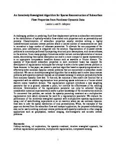
Informaation and Computational Technology and see how we can effecctively use succh information to address mentioned prroblems. In th he section that p meth hod of as-buillt data collectiion and repressentation is discussed. follows, our proposed Overview of the Proposed d As-Built R Representation To date, application of unordered u daiily site photoggraphs for rep presentation off construction n progress is ploited. The prrogress imagess are usually not n organized, uncalibrated, are widely variable and almost unexp taken under various v illumin nation, resoluttion, and imagge qualities. Developing com mputer vision and image processing tecchniques that can operate eeffectively with h such imagerry is a challengging task. With hin such scopee, one key challeenge is image registration, i..e., gauging co orrespondencees between im mages, and how w they relate to one another in a common 3D 3 coordinatee system. Thiss procedure is called Structuure from Motiion (SfM). ntial progress has been done in these areaas over the lasst two decadess (recent exam mples: Snavely While substan et al. 2008, Brrown and Low we 2005, Hartlley and Zisserrman 2004), so ome challenging aspects aree still unresolved. For F instance, there t is a neceessity to work with images that t are capturring sites whose appearancee is constantly changing c due to progress orr excessive mo ovement of ob bjects (e.g., sitte crew and machinery). m Also site phottographs are sometimes s takken only from specific activi vities under pro ogress or in panoramic fashions. Theese images mayy not carry en nough informaation for a mo ore global reco onstruction off the scene. Here we present state-of-th he-art steps wee implemented towards solvving this prob blem (Figure 1): 1
Figure 1. Steps S of Structture from Mo otion from leftt to right (exteended from Nistér N and Davvidson 2005) Feature Detectiion and Correspoondence: First sstep to use sitte images for reconstructio on of the as-b built scene is to t find distinct features f on eaach image, wh hich allow mattching these feeatures acrosss a subset of im mages. Despitte significant ressearch on featture detection n and matchin ng, only recen ntly researcherrs have propo osed techniquees that prove to o be successfuul in extractingg and detectin ng salient regiions (in imagee/scale space)) invariant witth respect to sccale, orientatio on and affinee transformatiions. Mikolajcczyk et al. (22005) reviews some recenttly developed vieew-invariant lo ocal image desscriptors and experimentally e y compare theeir performances. Structure from Motion M (SfM): Aims A to recon nstruct the un nknown 3D strructure and esstimate camerra positions an nd orientations from f a set of image featuure correspon ndences. Phottogrammetric techniques such s as bunddle adjustment (T Triggs et al. 1999) are cuurrently used in computer vision for 3D 3 reconstrucction and SfM M optimization. In our appro oach, we use tthe effective method m introdduced by (Snaavely et al. 20007, and, Brow wn and Lowe 20005). While th hese techniquees have been applied for image i navigattions and tourring, our papeer marks the firrst successful demonstratio on of SfM technique beingg applied to geospatial ph hotographs that capture a dyn namic construcction scene. Image based Rendering: R Follo owing Snavelyy et al. (20066), image baseed rendering techniques can c be used to t synthesize neew views of a scene from a set of photo ographs. In th hat paper, theese techniques are reviewedd. Our work is close c to Photo otour of Snavvely et al. (20006) and Sea off Images (Aliaaga et al. 20033) where a largge set of images is taken throuughout architeectural spaces.. In our work,, images are caasually acquireed on site (as in i obot (as in Aliaaga et al. 20033). Snavely et al. 2006), rather than being takken from fixedd locations orr on guided ro o Experimeental Setup an nd Results Discussion on Constructiion photo-loggs for our expeeriment have been collectedd on two consstruction sites on a daily basis. One off the authors has h been workking on these projects p and has h taken regullar daily consttruction p within n the day, scen nes that photos. Ratheer than only taaking photos ffrom specific locations or progress capture overaall depiction of the construcction site are captured c as weell. Figure 2 sh hows a varietyy of photo-loggs 5 538
26th Internattional Symposiuum on Automatiion and Roboticss in Constructionn (ISARC 20009) captured for f progress an nalyses in thesse projects. During the expeeriment a high h-resolution SLR camera waas carried. Th he choice of a high resolutio on camera waas based on th he possibility for fo further enh hancement of the algorithm so the qualityy of the imagess could be syn nthetically reduuced and the keypoint k detection could bee tested on synthetically lo owered resoluution images. To T assure the availability off data for furth her analysis, a larger num mber of photo os than averagee (about 200/day) have beeen collected to o allow more commonalities c s between im mages to be detected. d These projects are as follows: (1) Student Din ning Hall Projeect: A two-sto ory masonry and a curtain waall LEED Silvver certified buuilding with a partial basemeent of about 139,327sf. 1 Thiis project is a $36M steel frame f with composite deckiing in about 25 2 months of scheduled s work. (2) Residen nce Hall Projeect: A two-storry masonry an nd curtain walll LEED Silver certified buiilding with a partial p basemen nt of about 58,0000sf with struucture base beeing reinforcedd concrete fraame. This projject is 21 mon nths and the construction cost is app proximately $115M. These prrojects show two t major types of structurees which makkes them veryy attractive forr our case allow wing us to maake sure our suuggested apprroach works in n different conditionss.
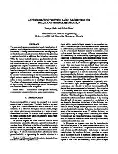
Figure 2. 2 An uncalibrrated subset o of Student Din ning/ Residence Hall Photo o-log collectedd for various site analyses using differrent cameras on o a daily basiis The firrst step is to fiind feature po oints in each im mage that couuld be used to estimate the initial i structure of the scene. In our work, we use the SIIFT keypoint detector d (Low we 2004), becaause of its goo od invariance to t nges and view and illuminatiion transform mations as well as its standard application in the computer scale chan vision dom main (Savaresee and Fei-Fei 22007). An imaage of 3MPixeels typically givves about 9,0000 to 11,000 features. An A example off detected feattures and num mber of featurees detected are illustrated in n Figures 3 an nd 4 respectively.
( An image taken t on 09/227/08 from Sttudent Diningg and Residencce Hall projeccts; (b) Same im mage Figure 3. (a) in grayscalee with SIFT feeature location ns visualized in n blue 16000 14000 12000
No. of SIFT Features
10000 8000 6000 4000 2000 0
mages 414345474951 No. of Im 1 3 5 7 9 111315171921 2325272931333537394
Figure 4. No. of SIFT features on th he 52-image suubset taken on n 09/27/08. No. N of SIFT feeatures within n the mages synthettically reducedd to 25% of th he original forrm (Tested im mage range off [6481, 151600]. Quality of im dimension ns = 2144 × 1424). 539
Informaation and Computational Technology Once the features have been detectedd over the dataset, we need to detect the number of matching nal speed, as exxperienced byy Snavely et al. (2006), we features in eacch image pair.. To minimizee computation use ANN’s prriority search algorithm andd limit each quuery to check a limited set. Furthermore, F instead of classifying false matches byy thresholdingg the distance to the nearestt neighbor, wee use the ratio test describedd hbors in j, with h distances d1 by Lowe (20004): for a featuure descriptor in image i, wee find the two nearest neigh and d2, then accept a the maatch if d1⁄d2< 0.6. If more than one featuure in i match hes the same feature fe in j, wee remove both of such match hes, as one off them is a falsse match. Figuure 5-left show ws the numberr of matched SIFT featuress within the suubset. Due to the sensitivityy of reconstrucction algorithm m to false mattches, we use an algorithm to remove succh false match hes. In our app proach, once the t matching features are detected d in an mental matrixx for the pair using u RANSA AC (Fischler an nd Bolles image pair, we robustly estiimate a fundam c g features to be b consistent 1981). The fuundamental maatrix removes false matchess as enforces corresponding under viewpo oint transform mation. In our m model, in each h iteration of RANSAC, a fundamental f m matrix is computed usiing the 8-poin nt algorithm off Hartley and Zisserman (20004), and then n the problem m is normalizedd to improve ro obustness to noises n (See Figgure 5-right fo or refined matched features)).
Figure 5. Nuumber of mattched SIFT features betweeen each image pair. Both axees show the caamera indices and the co olored dots vissualize the num mber of SIFT features in im mage pairs mattched before and a after the fundamental m matrix was fittted to the mattching featurees. Now, we recover r camerra extrinsic an nd intrinsic parrameters (extrrinsic parameters: rotation, translation; and intrinsic parameters: p fo ocal length andd distortion) for f each imagee and a 3D loccation for each h keypoint. The recoveredd parameters should be con nsistent, in thaat re-projectio on error; i.e., suum of distancces between th he projections off all 3D featurres and their ccorrespondingg image featurees, is minimized. This miniimization problem can be b formulatedd as using the bundle adjusttment algorith hm (See Triggss et al. 1999 fo or more details). First,, we estimate extrinsic e and iintrinsic param meters of a sin ngle image pairr. Since bundlle adjustment as other algorrithms for solvving non-lineaar problems may m get stuck in i bad local minima, m it is strrongly suggested by many research hers (e.g., Snavvely et al. 20007, Nistér 20044) to start with h a good initiaal image pair mera parameteers in the chossen pair. This initial pair forr SfM should have h a large and good estiimates for cam number of matches, but alsso have a largee baseline, so that the initiall scene can bee robustly reco onstructed. An A image pair thaat is poorly deescribed by a h homographic transformatio on stratifies thiis condition. A 2D image homography is a projectivee transformatio on that maps points from one o image plan ne to another image plane Z 20004). We find tthe homograp phy between alll image pairs using RANSA AC with an (Hartley and Zisserman outlier threshold of 0.4% of o maximum o of image width h and height, and a store the percentage p off feature matches that are inliers to the t estimated homography. We select thee initial image pair as that with w the lowestt percentage off inliers to the recovered ho omography, buut with at leastt 100 matchess (As experien nced by Snavelly et al. 2007). The T extrinsic camera c parameeters for this pair p are estimaated using Nisstér’s five poin nt algorithm (Nistér 2004),, and then thee tracks visiblee in the image pair are trianggulated. A two o-frame bundlle adjustment for this initiall pair is perforrmed. Next, w we add anotherr camera to th he optimization. We choosee the camera that examiness the largest nuumber of estim mated tracks, and initialize the new cameera’s extrinsic parameters using the Direect Linear Traansform (DLT T) technique (H Hartley and Zisserman Z 20004) within a RA ANSAC procedure. Fo or this RANSA AC step, we uuse an outlier threshold t of 0.4% 0 of maxim mum of imagee width or height. We usse focal length h from the EX XIF - exchangeeable image fille format- taggs of JPEG im mages to initialize the focal f length off the new cam mera and estim mate the intrinssic camera maatrix (see Snavvely et al. 20077 more details).. 5 540
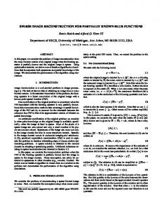
26th Internattional Symposiuum on Automatiion and Roboticss in Constructionn (ISARC 20009) Startingg from this in nitial reconstruucted scene, we w run the bun ndle adjustmen nt algorithm, allowing a new camera an nd feature poin nts it observess to change wh hile the rest of the model iss kept fixed. A feature pointt is added if itt is observed by b at least onee recovered cam mera, and if trriangulating th he location givves a wellconditioneed approximattion. We estim mate the condiitioning by co onsidering all pairs p of rays th hat could be used u to triangullate that pointt, and finding the pair of rayys with the maaximum anglee of separation n. If this maxim mum angle is larrger than a thrreshold (As exxperienced byy Snavely et al. 2007) then th he point is triaangulated. On nce the new points have beeen added, we run another global g bundle adjustment a to refine the enttire as-built olution with th he sparse bundle adjustmen nt library of reconstruccted scene. We use the miniimum error so Lourakis and a Argyros (22004). This prrocedure is rep peated for all cameras until no remainingg camera obserrves enough reeconstructed 3D 3 points to b be reliably reco onstructed. Ovverall only a subset s of the used u images will w be reconstruccted. This subset is not selected beforehaand, but is determined by th he algorithm. After A the as-built scene is reeconstructed, the t scene needds to be used for interactivee explorationss. Authors imp plemented an image-based rendering system s in Miccrosoft C++ .N NET using Microsoft M DirecctX9 graphics library. The present the as-built reconstrructed scene: (1) A set of keeypoints, in which w following data structuree is used to rep oint consists of o a 3D locatio on and a color that is averaaged out from all the progreess images that the each keypo keypoint is being observved from; (2) A set of cameeras, while thee extrinsic paraameters (transslation and p (fo ocal length andd distortion in n height and width w direction ns) are estimatted; rotation), and intrinsic parameters ween each poiint and all the cameras that observe the point. p A list off numbers of and (3) A mapping betw w observe the point, thee location of th he point in local coordinatees of the imagge, and the SIF FT cameras which keypoint in ndex are all sttored. While th his informatio on is stored, caameras wouldd be rendered as a frusta. Figuure 6a & b show w the reconstrructed sparse scene from th he same imagee subset and illlustrate 6 of the t registered cameras. Once O a cameraa is visited in tthis reconstruucted scene, th he camera frusstum is texturee-mapped with ha full resoluution of the im mage so user caan zoom in an nd acquire pro ogress and pro oductivity detaails as well as workspacee logistics. Figgure 6 – c, d, e and f show the t location off a frustum texxtured while demonstrating d g how the siite image is geeo-registered w with the as-buuilt point cloudd.
6 Sparsely reco onstructed sceene of Residen nce Hall usingg 52 images with wi 25% of im mage qualities. Six Figure 6. camerra frusta are reendered and geo-registered g . Conclusio on Our prop posed system marks the firrst system th hat allows as-b built construcction spatial information i t be to visualized using unordeered site photo o-logs. The demonstrated system s has th he following benefits: b (1) Remote R Constructioon Control Decision D Makiing: It allowss project maanagers, superintendents and a other prroject participants to virtuallyy walk on the construction site, as-of thee time the sceene has been reconstructedd and hemselves in those position ns that progreess images havve been taken n. Such an inteeractive user walkw position th through alllows progress to be discusssed. (2) It minimizes m the tim ime required to discuss the as--built scene: Prroject 541
Information and Computational Technology managers and superintendents will spend less amount of time discussing or explaining progress. Rather, they can spend more time on how a control decision could be made. Furthermore, reconstructed as-built scene and geo-registered images allow workspace logistics, safety issues, progress and even productivity of workforce and machinery to be remotely analyzed. Such an as-built system could also be beneficial in weekly contractor coordination meetings, as the workspace could be navigated through the virtual world. (3) Significant cuts in travel time and cost on project executives and architects – Project Executives and architects can study the reconstructed scene and geo-registered images, instead of spending time and money traveling to the jobsite. The reconstructed scene with as-built progress images can be beneficial, especially when the possibility of adding new photographs quickly to the system is considered. Even if a vanishing point of an interest is not registered within the reconstructed scene and is not present in geo-registered image dataset, the user (e.g., owner, project executive) can request the scene to be photographed, since the geo-registration removes confusion on perspective which is inherent in dynamic scenes. Those photographs taken can also be quickly geo-registered which allows a significant problem of progress communication to be resolved. (4) D4AR System- 4 Dimensional Augmented Reality Tool - This system could also be used as a baseline for an Augmented Reality tool wherein as-planned model could be geo-registered within the spatial as-built environment allowing construction progress deviations to be measured, analyzed and communicated. To that extent, authors have proposed D4AR – 4 Dimensional Augmented Reality - system which superimposes the planned model over point cloud and utilizes a traffic light color spectrum for visualizing progress (Golparvar-Fard et al. 2009); (5) Automatic progress tracking- Since this model geo-registers construction site photographs, it could serve as a rich baseline for automating progress monitoring through consistent visual detection of progress deviation and comparison with as-planned information; (6) Registering New Daily Site Photographs- New construction progress photographs can be registered within the system instantly. First, the user can open a set of progress images, and drag and drop each image onto its approximate location on the as-planned model. After each image has been dropped, the system can estimate location, orientation, and focal length of the new image by running the SfM algorithm. First, SIFT keypoints are extracted and matched to the keypoints of the cameras closest to the initial location; then the existing 3D points corresponding to the matches are identified; and finally, these matches are used to refine the pose of the new camera. Our preliminary results show perceived benefits and future potential enhancement of this new technology in construction, in all fronts of automatic data collection, processing and communication; though there are still many technical challenges in developing a full systematic progress monitoring system. These are currently being explored within the research projects highlighted in this paper. Acknowledgements We would like to thank Turner, Williams Brothers, Grunloh Construction companies especially Mr. Greg Cuttell, Mr. Bob Bursack and Mr. Nick Canellis from Turner as well as University of Illinois- Housing, Facilities and Services for their contributions to this project. This work is financially supported by NSF Award No. CMMI-0800500.
References [1] Abeid J., Allouche E., Arditi D., and Hayman M. (2003). PHOTO-NET II: a Computer-based Monitoring System Applied to Project Management, J of Automation in Constr, 12 (5), 603-616. [2] Aliaga D., Funkhouser T., Yanovsky D., and Carlbom I. (2003). Sea of images. IEEE Computer Graphics and Applications, 23 (6), 22-30. [3] El-Omari S. and Moselhi O. (2008). “Integrating 3D laser scanning and photogrammetry for progress measurement of construction work”. J. of Automation in Const. 18 (1), 1-9. [4] Golparvar-Fard M., Savarese S. and Peña-Mora F. (2009). “Interactive visualization of construction progress monitoring with D4AR – 4 Dimensional Augmented Reality- models.” Proc., Construction Research Congress, Seattle, WA, Apr 2009. [5] Golparvar Fard, M., Sridharan, A., Lee, S. and Peña-Mora, F. (2007) “Visualization of construction progress monitoring on time-lapsed photographs”, Proc., Constr. Mgmt & Econ, Reading, UK
542
26th International Symposium on Automation and Robotics in Construction (ISARC 2009) [6] Golparvar Fard M., Staub-French S., Po B. and Tory M. (2006). “Requirements for a mobile interactive workspace to support design development and coordination.” Proc., XI Joint Int. Conf. on Computing in Civil & Bldg Eng ASCE, Montreal, QC, 3587-3596. [7] Hartley R. and Zisserman A. (2004). Multiple view geometry, Cambridge Univ. Press, UK. [8] Jaselskis E., Cackler E., Walters R., Zhang J., and Kaewmoracharoen M. (2006). “Using scanning lasers for real-time pavement thickness measurement”. CTRE Project 05-205, National Concrete Pavement Tech Center, Iowa State Univ. [9] Kiziltas S., Akinci B., Ergen E. and Tang, P.o (2008). “Technological assessment and process implications of field data capture technologies for construction and facility/infrastructure management”, ITcon, 13, Sp. Issue Sensors in Const. and Infrastructure Mgmt., 134-154. [10] Lourakis M. and Argyros A. (2004). “The design and implementation of a generic sparse bundle adjustment software package based on the Levenberg–Marquardt algorithm” (Technical Report 340). Inst. of Computer Science-FORTH, Heraklion, Crete, Greece. [11] Lowe D. (2004). “Distinctive image features from scale-invariant keypoints”. Int Journal of Computer Vision, Vol. 60, No. 2, 91-110. [12] Meredith J. and Mantel S. (2003). Project Mgmt: A managerial approach. J. Wiley & Sons, 5th Ed. [13] Mikolajczyk K., Tuytelaars T., Schmid C., Zisserman A., Matas J., Schaffalitzky F., Kadir T., and van Gool L. (2005). “A comparison of affine region detectors”, Int J. of Computer Vis., 65 (½), 43-72. [14] Navon R. and Sacks R. (2007). “Assessing research in automated project performance control (APPC).” J. of Automation in Construction, 16 (4), 474-484. [15] Nistér D. (2004). “An efficient solution to the five-point relative pose problem”, IEEE Transactions on Pattern Analysis and Machine Intelligence (PAMI), 26 (6), 756-770. [16] Nistér D. and Davison A. (2005). “Real-Time motion and structure estimation from moving cameras”, Tutorial at CVRP 2005. [17] Oglesby C., Parker H., Howell G. (1989). Productivity improvement in construction, McGraw-Hill. [18] Poku S. and Arditi D. (2006). “Construction scheduling and progress control using geographical information systems”. J. of Computing in Civil Eng., 20 (5), 351-360. [19] Savarese S. and Fei-Fei L. (2007). :3D generic object categorization, localization and pose estimation”. IEEE Intern. Conf. in Computer Vision (ICCV). - Brazil, October, 2007. [20] Shih N.J., Wu M.C., and Kunz J. (2004). “The inspections of as-built construction records by 3D point clouds”. Stanford Univ., CIFE WP #090. [21] Snavely N., Seitz S., and Szeliski R. (2006). “Photo tourism: exploring photo collections in 3D.” Proc., ACM Transactions on Graphics, 25 (3), 835-846. [22] Snavely N., Seitz S., and Szeliski R. (2007). “Modeling the world from internet photo collections”. Int. J. of Computer Vision. [23] Snavely N., Seitz S., and Szeliski R. (2008). “Finding path through the world’s photos”. Proc., ACM Transactions on Graphics, 27 (3), 11-21. [24] Soibelman L., Wu J., Caldas C., Brilakis I. and Lin K.Y. (2008). “Management and analysis of unstructured construction data types.” J. of Advanced Engineering Informatics, 22, 15–27. [25] Su Y., Hashash Y., and Liu L.Y. (2006). “Integration of construction as-built data via laser scanning with geotechnical monitoring of urban excavation”. J. of Const Eng. Mgmt, 132 (12), 1234-1241. [26] Teizer J., Kim C., Haas C., Liapi K., and Caldas C. (2005). “Framework for real-time three-dimensional modelling of infrastructure”. Geology and Properties of Earth Materials 2005, Transportation Research Board Natl Research Council, Washington, 177-186.
543