1208
IEEE TRANSACTIONS ON MULTIMEDIA, VOL. 13, NO. 6, DECEMBER 2011
Spatial Audio Object Coding With Two-Step Coding Structure for Interactive Audio Service Kwangki Kim, Jeongil Seo, Seungkwon Beack, Kyeongok Kang, and Minsoo Hahn
Abstract—An interactive audio service is a new conceptual audio service that provides the users with opportunities for a variety of experiences on the alternative and advanced audio services. In the interactive audio service, users can freely control various audio objects to make their own audio sounds. A spatial audio object coding (SAOC) is a useful technology that can support most parts of the interactive audio service with a relatively low bit-rate, but is very poor to perfect gain control of a certain audio object, i.e., the target audio object. In this paper, the SAOC with a two-step coding structure is proposed to efficiently handle the target audio object as well as the normal audio objects. A transform coded excitation (TCX) based residual coding scheme is presented in the context of the sound quality enhancement. From experimental results, it can be noted that the various audio objects can be successfully handled with respect to the bit-rate and the sound quality by using the proposed two-step coding structure SAOC. Index Terms—Audio object, interactive audio service, residual coding, spatial audio object coding.
I. INTRODUCTION ONVENTIONAL audio services provide users with a stereo audio signal made by properly mixing various audio objects such as vocal, guitar, bass, etc. As the style of the provided audio signal is fixed and determined by a producer, users can only control the overall volume of the reproduced audio sound. With the increase of the users’ demand for alternative and advanced audio services, interactive audio services (IASs) such as the personalized audio service (PAS) and MUSIC 2.0 were introduced in Korea [1], [2]. In the IAS, the individual audio objects and the preset information are delivered to the users instead of the mixed audio signal made by the producer. This IAS has two kinds of operation modes, the preset and the interactive modes. Similar to the conventional audio service, in the preset mode, audio signals such as rhythmic music and Karaoke are predetermined by the
C
Manuscript received January 26, 2011; revised June 08, 2011; accepted August 22, 2011. Date of publication September 15, 2011; date of current version November 18, 2011. The associate editor coordinating the review of this manuscript and approving it for publication was Dr. Charles D. (Chuck) Creusere. K. Kim is with the Department of Information and Communications Engineering, Korea Advanced Institute of Science and Technology, Daejeon, Korea (e-mail:
[email protected]). J. Seo, S. Beack, and K. Kang are with Electronics and Telecommunications Research Institute, Daejeon, Korea (e-mail:
[email protected];
[email protected];
[email protected]). M. Hahn is with the Department of Electrical Engineering, Korea Advanced Institute of Science and Technology, Daejeon, Korea (e-mail:
[email protected]). Color versions of one or more of the figures in this paper are available online at http://ieeexplore.ieee.org. Digital Object Identifier 10.1109/TMM.2011.2168197
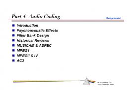
producer, and generated using the delivered audio objects and the preset information. Accordingly, the users can select one of the predetermined audio signals through the preset setting and can only control the volume of the selected audio signal. In the interactive mode, the users can create various audio signals according to their preferences. In other words, the users, like the producers, can produce their own audio signals through the free mixing of the audio objects. Although the IAS can satisfy the users’ demands on the new audio service, it may not be practical in the network and the broadcasting environments. The bit-rate greatly increases in proportion to the number of the audio objects since the audio coder, as shown in Fig. 1(b), has to code them separately [1]. Thus, the current IAS can have restricted applications. In other words, the IAS is feasible only when mass storages and wired/wireless broadband network/broadcasting systems are guaranteed. Therefore, for more successful applications, the bit-rate of the IAS should be reduced as much as possible. As a solution to this bit-rate problem, a spatial audio object coding (SAOC) scheme can be applied [3]–[6]. The basic idea of the SAOC is that the audio objects are represented as a down-mix signal with spatial parameters. As the SAOC only needs the bit-rate of the down-mix signal and the additional side information for the transmission, the bit-rate of the IAS can be greatly reduced. Nevertheless, the SAOC cannot be directly used for the IAS. Because the audio objects reconstructed by the SAOC are not the same as the original ones, the sound quality can be rather degraded. Generally, the degradation is not critical when the recovered audio objects are mixed together to generate the output signal. In contrast, if a specific audio object is fully suppressed or played alone, the sound quality degradation may be very severe. In other words, the precise control of a particular audio object that is possible in the IAS cannot be supported by the SAOC. Therefore, to develop the IAS fully supported by the SAOC, the current SAOC should be enhanced. As a method to enhance the SAOC performance, a harmonic elimination scheme was proposed by Park et al. [23], [24]. Park et al. tried to enhance the sound quality by eliminating the undesired harmonic components included in the decoded output signals when the specific audio object is fully suppressed. Although the harmonic elimination scheme could enhance the SAOC performance rather successfully, the sound quality improvement by the harmonic elimination scheme was not enough for the IAS. Moreover, the harmonic elimination scheme could not improve the sound quality of the specific audio object. Therefore, a new scheme should be needed and we propose a two-step SAOC structure and a residual coding scheme. In the proposed two-step SAOC, if there is a target object for the precise control, then
1520-9210/$26.00 © 2011 IEEE
KIM et al.: SPATIAL AUDIO OBJECT CODING WITH TWO-STEP CODING STRUCTURE FOR INTERACTIVE AUDIO SERVICE
1209
Fig. 1. System structures of the conventional and interactive audio services. (a) Conventional audio service. (b) Interactive audio service.
II. SPATIAL AUDIO OBJECT CODING
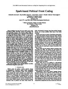
Fig. 2. General structure of the SAOC [3].
the normal audio objects except the target object are coded by the current SAOC scheme and the target object is handled by an alternative SAOC scheme. As it is important to recover the target object more precisely, the alternative SAOC should focus on the near-perfect reconstruction of the target object. Hence, a residual coding is used as the alternative SAOC scheme in order to guarantee the high sound quality [7]. Finally, the IAS can be supported by the enhanced two-step coding structure SAOC, while saving the bit-rate and maintaining the reasonable sound quality. This paper is organized as follows: Section II introduces the SAOC scheme briefly. In Section III, a problem caused by the SAOC for the IAS is presented and the two-step coding structure SAOC and its coding scheme are described. In Section IV, the residual coding scheme is explained in detail. Finally, the experimental results and conclusions are given in Sections V and VI, respectively.
A. Overview of the SAOC The SAOC consists of the encoding, the decoding, and the rendering parts as shown in Fig. 2 [3]. In the encoding part, the input audio objects are represented as the mono or stereo down-mix signal with spatial parameters. For the calculation of spatial parameters, the input audio objects are first transformed by the DFT into the frequency domain signals. The transformed signals are grouped into sub-bands to be well adapted to human perception, as shown in Table I [8]. As a main spatial parameter, the object level difference (OLD) is used. The OLD is defined as the power ratio among the input audio objects, and it can be calculated as (1) where and are the estimated power of the audio object and the maximum power of the input audio objects frame, respectively. , , and at the sub-band of the are the numbers of the frames, the input audio objects, and the sub-bands, respectively. In the decoding part, the audio objects are simply reconstructed using the transmitted down-mix signal and spatial parameters. Using the spatial parameters, the gain factors of the audio objects can be calculated as (2)
1210
IEEE TRANSACTIONS ON MULTIMEDIA, VOL. 13, NO. 6, DECEMBER 2011
TABLE I PARTITION BOUNDARIES FOR THE CASE OF PARTITION BANDWIDTHS OF 2 ERB, A DFT SIZE OF 2048, AND A SAMPLING RATE OF 44.1 kHz
The calculated gain factors are simply multiplied to the transformed down-mix signal by the DFT using Table I:
(3)
where and are the reconstructed audio object and the down-mix signal in the frequency domain, respecand are the beginning and end points of a tively. certain sub-band , respectively. In the rendering part, the recovered audio objects are rendered to generate the desired output signals according to the user interaction. If there is a rendering matrix for -channel output , then the rendered output signal can be obtained as signal,
(4)
(5) is the channel output-signal in the frequency where domain, and is the DFT size. Finally, the frequency-domain output signal is transformed by an IDFT into the time-domain signal. B. Problem of the SAOC The SAOC should support two main application scenarios of the IAS. One is the music remix, where the users can make their own music through the amplification and attenuation of the level of the audio objects. The other is the Karaoke/Solo, where the specific audio object, typically lead vocal, is fully suppressed or played alone. For the music remix application, the SAOC demonstrated good performance in terms of the bit-rate and sound quality, because the bit-rate of the SAOC is slightly higher than that required for the transmission of one audio object, and the simple gain control of each audio object rarely affects the overall sound quality. Fig. 3 illustrates an example of the original and the decoded signals in the remix of the audio objects, and it can be observed that the original and the decoded signals show the similar spectrogram.
Fig. 3. Spectrogram comparison of the original and the decoded signals in the remix of the audio objects. (a) Original signal. (b) Decoded signal.
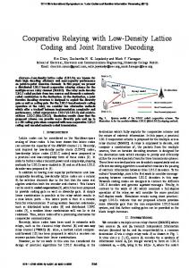
However, for the Karaoke/Solo application, the normal SAOC has very poor sound quality. As the SAOC adopts the sub-band processing having low-frequency resolution and the audio objects are recovered from the down-mix signal, the recovered audio objects are not equal to the original ones. Therefore, when the specific audio object is fully suppressed or played alone, the sound quality is very poor. In particular, the spectral null and the undesired sound causing severe sound quality degradation are easily observed in the output signal. Fig. 4 shows an example of the original and the decoded signals in the Karaoke/Solo application. As shown in Fig. 4, the spectrogram of the decoded signal is much different from that of the original signal. The decoded signal has the undesired harmonic components that came from the fully suppressed vocal object and it also has many spectral nulls. III. SAOC WITH TWO-STEP CODING STRUCTURE A. Two-Step Structure of the SAOC To enhance the performance of the SAOC for the Karaoke/ Solo application, a two-step structure is proposed to handle the normal and the target audio objects sequentially. In other words, the normal and the target audio objects can be processed by the normal and the alternative SAOC scheme, respectively. Fig. 5 illustrates the proposed two-step structure of the SAOC. At the encoder side, the normal input audio objects are first represented as the normal down-mix signal and the step I parameters. The normal down-mix signal and the step I parameters are delivered to the second stage of the SAOC and the bit-stream
KIM et al.: SPATIAL AUDIO OBJECT CODING WITH TWO-STEP CODING STRUCTURE FOR INTERACTIVE AUDIO SERVICE
1211
At the decoder side, the normal down-mix signal and the target audio object are recovered using the transmitted down-mix signal and the step II parameters that are extracted at the second encoding stage. Again, the normal audio objects are reconstructed using the recovered normal down-mix signal and the step I parameters that are extracted at the first encoding stage. All the recovered audio objects are sent to the renderer, and the desired output signal is generated according to the user interaction. B. Step II Coding Scheme The step II coding consists of two parts. The first part is a generic coding in which the normal down-mix signal and the target audio object are encoded and decoded in the sense of the signal power, similar to the step I coding. The second part is a supplementary coding where the recovered signals from the first part are compensated to be similar to the original signals as much as possible. The generic scheme of the step II coding is almost the same as that of the normal SAOC. Similar to the OLD, the channel level difference (CLD) is used as the spatial parameter and is defined as the power ratio between two input signals [7], [9], [10]. The CLD can be calculated as Fig. 4. Spectrogram comparison of the original and the decoded signals in the full suppression of the vocal object. (a) Original signal. (b) Decoded signal.
(6) where and are the estimated power of the normal down-mix signal and the target audio object, respectively. Using the CLD, the gain factors of the normal down-mix signal and the target audio object are recalculated as (7)
and are the gain factors of the target where audio object and the normal down-mix signal, respectively. Using Table I, these gain factors are multiplied to the down-mix signal in the frequency domain. The target audio object and the normal down-mix signal are obtained in the frequency domain as
Fig. 5. Proposed two-step structure of the SAOC. (a) Two-step SAOC encoder. (b) Two-step SAOC decoder.
formatter, respectively. Then, the normal down-mix signal and the target audio object are encoded using the alternative coding scheme that focuses on the precise reconstruction and full suppression of the target audio object. From this stage, the final down-mix signal and the step II parameters are generated.
(8) and are the recovered target audio where object and the normal down-mix signal in the frequency domain, respectively. However, these recovered signals are not suitable for the Karaoke/Solo application because they are quite different from the original signals. To make the recovered signals similar to the original signals, the difference between the original and the recovered signals should be minimized. To achieve this goal, the residual coding can be used as the supplementary coding. The residual coding is a useful technology that reduces the gap between the parametric description of the audio signals and the transparent sound quality [7].
1212
IEEE TRANSACTIONS ON MULTIMEDIA, VOL. 13, NO. 6, DECEMBER 2011
The residual signal is simply calculated using the input signals and the CLD. Namely, suppose there are two input signals, and , the down-mix signal, , and the residual signal, . If the input signals are encoded and decoded using the generic step II coding scheme, then it can be assumed that the two signals can be recovered as (9) where and are the recovered signals, while and are the gains of the recovered signals calculated using the CLD. Hence, the above equation can be rewritten as (10) If the recovered signals are perfectly the same as the original signals, then the residual signal can be calculated as (11) Using (7), (11) can be generalized as
(12) and are the target object and the where normal down-mix signals in the frequency domain, respectively. From (12), it is obvious that the residual signal has all the frequency components of the target audio object and the normal down-mix signal. Using the residual signal, (8) can be updated as
(13) is the residual signal processed by the residual where coding scheme. When (13) is compared with (8), it can be noted that the residual signal eliminates the undesired components included in the recovered target audio object and the normal down-mix signal. Moreover, the missed components of the recovered target audio object and the normal down-mix signal can be compensated by the residual signal. In other words, the residual signal can remove the spectral null and the undesired sound observed in the recovered signals. IV. RESIDUAL CODING SCHEME The residual coding is a useful technology to guarantee the transparent sound quality in speech and audio coding. An advanced audio coding low complexity (AAC-LC) has been more frequently used for stereo coding [11]. As the AAC-LC shows good performances with rather low complexity, it can be directly used to code the residual signal in the implemented SAOC. However, since the AAC-LC has a different time to frequency
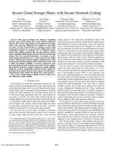
transform, modified discrete cosine transform (MDCT), and it causes the coding delay, we implemented a new residual coder based on a transform coded excitation (TCX). A. Effective Bandwidth of the Residual Signal As the residual signal is calculated using the input objects as in (12), it is natural to assume that the residual signal has almost the same bandwidth when compared with that of the input objects. Thus, the residual signal may be coded with a considerable bit-rate that is almost similar to that for the transmission of the down-mix signal. Certainly, the residual coding at the high bit-rate can enhance the overall sound quality. However, due to the limited bit-rate, the residual coding cannot be performed at the high bit-rate and consequently the residual signal may be distorted. Therefore, we have to select the effective bandwidth of the residual signal. In other words, to efficiently code the residual signal with the limited bit-rate, the specific frequency components of the residual signal that can dominantly affect the overall sound quality should be handled more intensively. To determine the effective bandwidth of the residual signal, we need to consider the human hearing property and the target audio object characteristics. Since the human hearing is relatively insensitive to the high frequency regions [12], the high frequency components of the residual signal can be excluded. In addition, as the vocal sound is the primary target audio object in most cases, the effective bandwidth can be considered as the frequency regions from 0 to 8 kHz. In [13], it can also be found that the 0–5 kHz frequency components of the residual signal are adequate to obtain reasonable sound quality. Hence, we have used the 0–5.5 kHz frequency components of the residual signal. B. Coding Scheme To code the residual signal, we implemented the TCX based residual coder. The basic principle of the residual coder is very similar to that of the TCX mode in a universal speech and audio coder [14]–[17]. However, since the residual signal is band-limited as mentioned above, and as it is used to complement the sound quality of our SAOC system, a structure of the residual coder can be simplified. In other words, the residual coder does not adopt the adaptive frame size, overlapping, mode selection, noise filling, etc., described in [14]–[17]. Fig. 6 illustrates the structure of the residual coder. At the encoder side, the residual signal is first transformed into the time domain representation by the IDFT, because the residual signal is extracted in the frequency domain as in (12). Then, the residual signal is represented as the linear predictive coding (LPC) coefficients and the excitation signal through a linear prediction (LP) analysis. The LPC coefficients are transformed into line spectral frequencies (LSFs) and are directly quantized as in [17]. The excitation signal is transformed by the DFT and the complex transformed excitation signal is quantized using self-scalable algebraic VQ [18]–[20]. At the decoder side, the transmitted LSFs are dequantized and reversely transformed into the LPC coefficients. The dequantized excitation signal in the frequency domain is transformed into the time domain representation by the IDFT. The residual
KIM et al.: SPATIAL AUDIO OBJECT CODING WITH TWO-STEP CODING STRUCTURE FOR INTERACTIVE AUDIO SERVICE
1213
Fig. 6. Structure of the residual coder. (a) Encoder structure. (b) Decoder structure.
signal is recovered through an LP synthesis using the recovered LPC coefficients and the recovered excitation signal. Finally, the reconstructed residual signal is transformed into the frequency domain representation by the DFT and is added or subtracted to the recovered audio objects, as in (13). Fig. 7 shows the decoded output signals with and without the residual coding in the full suppression of the vocal object. As indicated in Fig. 7(b) and (c), the undesired sound (harmonic components) and the spectral nulls in the Karaoke/Solo application can be eliminated by adopting the residual coding. V. EXPERIMENTAL RESULTS A. Test Conditions
over, the compression and the reconstruction of the audio objects are accomplished by the simple spatial parameters. However, in the two-step coding, the test case II, the overall complexity increases due to the residual coding. The average processing time and the used memory for the implemented SAOC are given in Table IV. Both the normal coding and the two-step coding are running in real-time on a laptop computer (2.6 GHz Pentium 4 processor). Especially, the complexity of the SAOC decoder is lower than that of the SAOC encoder. In addition, Table V shows the complexity comparison between the implemented residual coder and the AAC-LC. The complexity of the TCX based residual coder is slightly higher than that of the AAC-LC.
For all the tests, five popular Korean songs sampled at 44.1 kHz with 16 bit resolution, listed in Table II, were used. Each item consisted of four to six audio objects, such as vocal, bass, guitar, drum, piano, and rhythm, and was shorter than 20 s. All the test materials are available at [21]. To confirm the performance of the SAOC system, we used two test cases that are listed in Table III. For all the test cases, we checked the consumed bit-rate and the sound quality of the SAOC system for the normal mixing of the audio objects and the full suppression or the solo representation of the target audio object.
C. Bit-Rate Results Table VI shows the bit-rate results for all the test cases. For all the test cases, the down-mix signal was coded with AAC at 128 kbps. For the normal mixing of the audio objects, the average side information per channel was about 1.7 kbps. On the other hand, for the full suppression or the solo representation of the target audio object, the average bit-rate per channel was about 4.5 kbps. Since the residual signal should be additionally coded with a considerable bit-rate for the perfect control of the target audio object, inevitably the bit-rate of the test case II increases. Here, we used 15 kbps per channel for the residual coding.
B. Complexity
D. Subjective Listening Test Results As a subjective listening test, the MUSHRA test was performed [22]. Three and six systems were used for the test case I and II, respectively, and they are listed in Table VII. For the subjective listening test, we generated the output signals using the rendering matrix given in Table VIII. The listening test was per-
The complexity of the implemented SAOC is dependent on the operation modes and the number of the audio objects. In the normal SAOC coding, the test case I, the complexity of the implemented SAOC is reasonably low. It is because the most demanding operations for the SAOC are the FFT and IFFT. More-
1214
IEEE TRANSACTIONS ON MULTIMEDIA, VOL. 13, NO. 6, DECEMBER 2011
TABLE IV COMPLEXITY OF THE IMPLEMENTED SAOC
TABLE V COMPLEXITY COMPARISON BETWEEN THE IMPLEMENTED RESIDUAL CODER AND THE AAC-LC
TABLE VI BIT-RATE RESULTS
TABLE VII SYSTEMS UNDER TEST Fig. 7. Spectrogram comparison of the decoded output signals with and without the decoded residual signal when the vocal object is fully suppressed. (a) Original signal. (b) Decoded signal without residual coding. (c) Decoded signal with residual coding.
TABLE II TEST MATERIALS
TABLE III TEST CASES
formed at a special listening room using Stax Lambda Pro headphone with Fireface UC and eight experienced listeners evaluated the decoded audio quality of the test items in each trial.
As shown in Fig. 8, the SAOC shows good sound quality for both the rhythmic and the harmonic music for the test case I. Therefore, the SAOC can be directly used for handling the audio objects with the purpose of normal mixing. On the other hand, the SAOC cannot be applied for the full suppression and the solo representation of a certain audio object because it shows poor sound quality in the test case II as shown in Fig. 9. In other words, the SAOC does not have the ability to control the target object. However, from Fig. 9, it can be confirmed that the performance of the SAOC can be improved by the enhanced SAOC, because the sound quality of the enhanced SAOC
KIM et al.: SPATIAL AUDIO OBJECT CODING WITH TWO-STEP CODING STRUCTURE FOR INTERACTIVE AUDIO SERVICE
1215
TABLE VIII RENDERING MATRIX
Fig. 9. Subjective listening test results for the test case II. (a) Solo representation. (b) Full suppression.
Fig. 8. Subjective listening test results for the test case I. (a) Rhythmic music. (b) Harmonic music.
is much better than that of the SAOC. Moreover, the sound quality of the enhanced SAOC is slightly better than that of the SAOC with the AAC-LC and significantly better than that of the SAOC with the harmonic elimination scheme. Consequently, from the listening test results, we can conclude that the implemented SAOC shows good performance for both music remix and Karaoke/Solo applications. VI. CONCLUSION The IAS is a new conceptual audio service that can provide the users with the interactivity, but it is feasible only when mass storages and wired/wireless broadband network/broadcasting systems are guaranteed. Since the SAOC is a useful technology to efficiently represent various audio objects with respect to the bit-rate and the sound quality, it was applied to solve the
bit-rate problem of the IAS resulting in the limitation to the application area. However, the audio objects reconstructed by the SAOC are not the same as the original ones, so the sound quality can be rather degraded. In particular, the sound quality degradation is very severe when a specific target audio object is fully suppressed or played alone. For efficiently handling the target audio object, we proposed the SAOC with the two-step coding structure. By using the proposed SAOC structure, the normal and the target audio objects are sequentially handled by the normal SAOC and the alternative one, respectively. As it is important to recover the target object more precisely, the alternative SAOC should focus on the near-perfect reconstruction of the target object. Hence, a residual coding is used as the alternative SAOC scheme in order to guarantee the high sound quality. For the residual coding, the TCX based residual coder is newly implemented. Finally, the target audio object can be precisely controlled by the SAOC with the proposed two-step coding structure. In addition, the IAS can be successfully supported by the SAOC with the proposed two-step coding structure and it can be possible in the wired and wireless environments. The experimental results show that the proposed SAOC scheme guarantees good sound quality for both the normal mixing of
1216
IEEE TRANSACTIONS ON MULTIMEDIA, VOL. 13, NO. 6, DECEMBER 2011
the audio objects and the full suppression or solo representation of the target object. REFERENCES [1] D. Jang, T. Lee, Y. Lee, and J. Yoo, “A personalized preset-based audio system for interactive service,” in Proc. 121st AES Conv., San Francisco, CA, 2006, Preprint 6904. [2] Consideration of Interactive Music Service, ISO/IEC JTC1/SC29/ WG11 (MPEG), Archamps, Apr. 2008, Document M15390. [3] J. Herre and S. Disch, “New concepts in parametric coding of spatial audio: From SAC to SAOC,” in Proc. 2007 Int. Conf. Multimedia and Expo, Jul. 2007, pp. 1894–1897. [4] Call for Proposals on Spatial Audio Object Coding, ISO/IEC JTC1/ SC29/WG11 (MPEG), Jan. 2007, Document N8853. [5] ISO/IEC 2003-2 Information Technology-MPEG AudioTechnologies—Part 2: Sptatial Audio Object Coding (SAOC), 2010. [6] J. Breebaart, J. Engdegard, C. Falch, O. Hellmuth, J. Hilpert, A. Hoelzer, J. Koppens, W. Oomen, B. Resch, E. Schuijers, and L. Terentiev, “Spatial Audio Object Coding (SAOC)—The upcoming MPEG standard on parametric object based audio coding,” in Proc. 124th AES Conv., Amsterdam, The Netherlands, 2008, Preprint 7377. [7] J. Herre, H. Purnhagen, J. Breebard, C. Faller, S. Disch, K. Kjorling, E. Schuijers, J. Hilpert, and F. Myburg, “The reference model architecture for MPEG spatial audio coding,” in Proc. 118th AES Conv., Barcelona, Spain, 2005, Preprint 6447. [8] C. Faller and R. Baumgarte, “Binaural cue coding-Part II: Schemes and application,” IEEE Trans. Speech Audio Process., vol. 11, no. 6, pp. 520–531, Nov. 2003. [9] Information Technology-MPEG AudioTechnologies—Part 1: MPEG Surround, ISO/IEC 23003-1, 2007. [10] K. Kim, S. Beack, J. Seo, D. Jang, and M. Hahn, “Improved channel level difference quantization for spatial audio coding,” ETRI J., vol. 29, no. 1, pp. 99–102, Feb. 2007. [11] Information Technology-Coding of Audio-Visual Objects–Part 3: Audio, ISO/IEC 14496-3:2005, 2006. [12] E. Zwicker and H. Fastl, Psychoacoustics. Berlin, Germany: Springer-Verlag, 1999. [13] Proposed Improvement for MPEG SAOC, ISO/IEC JTC1/SC29/WG11 (MPEG), Oct. 2007, Shenzen, Document M14985. [14] R. Lefebvre, R. Salami, C. Laflamme, and J.-P. Adoul, “High quality coding of wideband audio signals using transform coded excitation (TCX),” in Proc. ICASSP’94, Apr. 1994, pp. I.193–I.196. [15] B. Bessette, R. Salami, C. Laflamme, and R. Lefebvre, “A wideband speech and audio codec at 16/24/32 kbit/s using hybrid ACELP/TCX techniques,” in Proc. IEEE Workshop Speech Coding, Porvoo, Finland, Jun. 20–23, 1999, pp. 7–9. [16] B. Bessette, R. Lefebvre, and R. Salami, “Universal speech/audio coding using hybrid ACELP/TCX techniques,” in Proc. ICASSP’05, Mar. 2005, pp. III.301–I.304. [17] 3GPP TS 26.190, 3rd Generation Partnership Project, Technical Specification Group Services and Systems Aspects, Speech Codec Speech Processing Functions, AMR Wideband Speech Codec; Transcoding Functions. [18] J. H. Conway and N. J. A. Sloane, “A fast encoding method for lattice codes and quantizers,” IEEE Trans. Inf. Theory, vol. IT-29, no. 6, pp. 820–824, Nov. 1983. [19] M. Xie and J. P. Adoul, “Embedded algebraic vector quantization (EAVQ) with application to wideband audio coding,” in Proc. ICASSP’96, May 1996, pp. 240–243. [20] S. Ragot, B. Bessette, and R. Lefebvre, “Low-complexity multi-rate lattice vector quantization with application to wideband TCX speech coding at 32 kbit/s,” in Proc. ICASSP’04, May 2004, pp. 501–504. [21] [Online]. Available: ftp://143.248.158.110(contact us for ID and password). [22] ITU-R Recommendation, Method for the Subjective Assessment of Intermediate Sound Quality (MUSHRA), ITU, BS 1543-1. Geneva, Switzerland, 2001. [23] J. Park, K. Kim, J. Seo, and M. Hahn, “Modified spatial audio object coding scheme with harmonic extraction and elimination structure for interactive audio service,” in Proc. INTERSPEECH 2010, Sep. 26–30, 2010, pp. 2906–2909. [24] J. Park, J. Hong, K. Kim, and M. Hahn, “Harmonic elimination structures for Karaoke mode in spatial audio object coding scheme,” in Proc. IEEE Int. Conf. Consumer Electronics, Jan. 9–12, 2011, pp. 838–839.
Kwangki Kim received the B.S. degree in electronic engineering from Korea Aviation University, Koyang, South Korea, in 2002, and the M.S. degree in electronic engineering from Information and Communications University, Daejeon, South Korea, in 2004. He is currently pursuing the Ph.D. degree in the Department of Information and Communications Engineering at Korea Advanced Institute of Science and Technology. His research interests include multi-channel audio coding, multi-object audio coding and their applications.
Jeongil Seo received the B.S., M.S., and Ph.D. degrees in electronic engineering from Kyungpook National University, Daegu, South Korea, in 1994, 1996, and 2005, respectively. Currently, he is with the Electronics and Telecommunications Research Institute, Daejeon, South Korea. His research interests include 3-D audio, audio signal processing, multi-channel audio coding, multi-object audio coding and their applications.
Seungkwon Beack received the B.S. degree in electronic engineering from Korea Aviation University, Koyang, South Korea, in 1999, and the M.S. and the Ph.D. degrees in electronic engineering from Information and Communications University, Daejeon, South Korea, in 2001 and 2005. Currently, he is with the Electronics and Telecommunications Research Institute, Daejeon, South Korea. His research interests include 3-D audio, audio signal processing, multi-channel audio coding, multi-object audio coding and unified speech and audio coding.
Kyeongok Kang received the B.S. and the M.S. degrees from the Physics Department at Busan National University, Busan, South Korea, in 1985 and 1988, respectively, and the Ph.D. degree in electrical engineering from Korea Aviation University, Koyang, South Korea, in 2004. Currently, he is with the Electronics and Telecommunications Research Institute, Daejeon, South Korea. His research interests include 3-D audio, audio signal processing, audio coding, MPEG-7, and TV-Anytime.
Minsoo Hahn received the B.S. and the M.S. degrees in electrical engineering from Seoul National University, Seoul, South Korea, in 1979 and 1981, respectively, and the Ph.D. degree in electrical and electronics engineering from University of Florida, Gainesville, in 1989. From 1990 to 1997, and he was with the Electronics and Telecommunications Research Institute (ETRI), Daejeon, South Korea. In 1998, he was a faculty member of the School of Engineering, Information and Communications University. Currently, he is a Full Professor in electrical engineering at Korea Advanced Institute of Science and Technology (KAIST) and a Director in Digital Media Laboratory, KAIST. His research interests include speech and audio coding, speech synthesis, noise reduction, and VoIP.