OPERATIONAL ENVIRONMENT
SPECIFICATION, DEVELOPMENT AND VALIDATION OF AN ACOUSTIC MODEM FOR UNDERWATER COMMUNICATION Especificação, desenvolvimento e validação de um modem acústico para comunicação submarina Jefferson Osowsky1, Fábio Contrera Xavier2, Celso Marino Diniz3, Marcus Vinícius da Silva Simões4, Leonardo Martins Barreira5
Abstract: This study aims to present the specification, development and validation of an acoustic modem prototype for underwater communication. It stemmed from an acoustic communication experiment, aimed at transmitting and receiving short texts in Morse code through a narrowband digital channel. In this first version, the modem uses frequency shift keying (FSK) modulation/demodulation to send/receive data to/from the receiver. Before transmission, to improve its reliability, data are coded via a convolutional forward error correction (FEC) code and then interleaved in order to reduce distortion caused by the communication channel and the burst error between successive symbols, respectively. A recent data transmission/reception experiment in a shallow water communication channel has been conducted in May 2012 at Enseada dos Anjos, Rio de Janeiro, to assess the performance of the first prototype. Keywords: Digital Communication. Underwater Communication. Underwater Acoustic. Underwater Acoustic Modem. Frequency Shift Keying Modulation. Forward Error Correction Code. Convolutional Coding.
Resumo: Este trabalho visa apresentar a especificação, desenvolvimento e validação de um protótipo de modem acústico para comunicação submarina. Este trabalho surgiu a partir de um experimento de comunicação acústica que tinha por objetivo transmitir e receber textos curtos em código Morse através de um canal digital de banda estreita. Nesta primeira versão, o modem utiliza a modulação e demodulação por chaveamento de frequência (frequency shift keying - FSK) na transmissão e recepção dos dados, respectivamente. Antes da transmissão, para melhorar sua confiabilidade, os dados são processados por um código de correção antecipativo de erro (forward error correction - FEC) convolucional e então embaralhados (do inglês, interleaved) de forma a reduzir a distorção causada pelo canal de comunicação e o erro de burst entre símbolos contíguos, respectivamente. Um experimento recente de transmissão/recepção de dados em um canal de comunicação em águas rasas foi realizado em Maio 2012 na Enseada dos Anjos, Rio de Janeiro, para avaliar o desempenho deste primeiro protótipo. Palavras-chave: Comunicação Digital. Comunicação Submarina. Acústica Submarina. Modem Acústico Submarino. Modulação por Chaveamento de Frequência. Código de Correção Antecipativa de Erro. Codificação Convolucional.
1. Doctoral Student in Computational Modeling, National Laboratory for Scientific Computation – Petrópolis, RJ – Brazil. Fellow of DTI/CNPq, Underwater Communication Division, Instituto de Estudos do Mar Almirante Paulo Moreira – Arraial do Cabo, Rio de Janeiro – Brazil. Email:
[email protected] 2. Master’s Degree Student in Oceanic Engineering, Universidade Federal do Rio de Janeiro – Rio de Janeiro, RJ – Brazil. Assistant in the Underwater Communication Division, Instituto de Estudos do Mar Almirante Paulo Moreira – Arraial do Cabo, Rio de Janeiro – Brazil. Email:
[email protected] 3. Electronic Engineer, Universidade Estadual de Campinas – Campinas, SP – Brazil. E-mail:
[email protected] 4. Doctoral Student in Oceanic Engineering, Universidade Federal do Rio de Janeiro – Rio de Janeiro, RJ – Brasil. Supervisor of the Underwater Acoustics Group, Instituto de Estudos do Mar Almirante Paulo Moreira – Arraial do Cabo, RJ – Brazil. E-mail:
[email protected] 5. Doctor in Oceanic Engineering, Universidade Federal do Rio de Janeiro – Rio de Janeiro, RJ – Brasil. Supervisor of the Underwater Acoustic Systems Group, Instituto de Pesquisas da Marinha – Ilha do Governador, RJ – Brazil. E-mail:
[email protected]
|2| Revista Pesquisa Naval, Brasília - DF, n. 26, 2014, p. 2-10
Jefferson Osowsky, Fábio Contrera Xavier, Celso Marino Diniz, Marcus Vinícius da Silva Simões, Leonardo Martins Barreira
1. INTRODUCTION Over the years, underwater acoustic communication has been attracting attention from research institutes around the world due to its potential application in fields such as oceanography, oil and gas and naval defense (CHITRE et al., 2008a; CHITRE et al., 2008b; LACOVARA, 2008). In addition, given the ease with which sound travels in the ocean, acoustic communication is a more suitable method for transmitting and receiving data compared to electromagnetic communication. For example, the attenuation of a 1kHz electromagnetic wave propagating in the ocean is approximately 60 times greater than the attenuation of an acoustic wave in the same frequency. On the other hand, high-speed communication in underwater acoustic channels is challenging because of the narrow bandwidth, the multiple paths of the transmitted signal and the Doppler effect, among other limiting factors (LACOVARA, 2008; LI et al., 2008a, 2008b). In literature, there are studies that aim to reduce some of these effects through the use of multi-carrier modulation (BERGER et al., 2010; LI et al., 2008b; YEUNG et al., 2003), in particular, orthogonal frequency division multiplexing – OFDM (CARRASCOSA; STOJANOVIC, 2010; LI et al., 2008a; LEE et al., 2006; TU et al., 2011), including in shallow water acoustics, where the effect of multiple paths is enhanced (PANARO et al., 2012; RADOSEVIC et al., 2010). Therefore, in this type of data communication, many yet unsolved problems can be found. In this study, the authors briefly present the stages of development of an acoustic modem prototype, implemented in a MatLab environment, and the preliminary results obtained in the transmission/reception of data via an underwater acoustic channel, in shallow waters, subject to additive noise, treated as a white Gaussian process (additive white Gaussian noise – AWGN). The objective of this project is the development of a fully national acoustic modem that can be incorporated into the communication systems of the Brazilian Navy. This paper is organized as follows: Section 2 describes the experiment that led to the design of the acoustic modem prototype for underwater communication; Section 3 describes the development of this prototype to date; the results, achieved by another
study, conducted at Enseada dos Anjos and its findings, are presented in Sections 4 and 5, respectively.
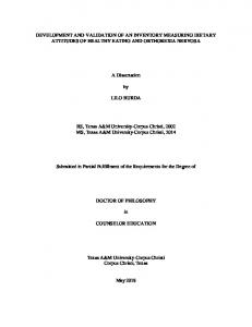
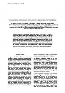
2. HISTORY The underwater acoustic modem prototype arose from the implementation of a simple, howevr effective acoustic communication code developed in a Matlab environment by researchers of the Underwater Acoustics Group (UAG) of Instituto de Estudos do Mar Almirante Paulo Moreira (IEAPM), whose main objective was the narrowband transmission of texts in Morse code. This experiment consisted of two modules: transmission/encoding module (MTx) and receiving/decoding module (MRx). The communication protocol specified for this initial experiment was based on the rule of dots, dashes and pauses described by Morse code, i.e., a point is encoded as a form of continuous waveform (CW ) with duration of 0.3 seconds, and unit amplitude; a dash was represented by the combination of three consecutive points. Furthermore, a pause, encoded as a silence period equals to the dot separated dots and dashes. Two letters and two words are separated by two and three pauses, respectively. As an illustration of this protocol, the signal encoding the text “MARINHA DO BRASIL” (Brazilian Navy) is shown in Figure 1. Given any text, the MTx module was responsible for encoding it in Morse code symbols to build the signal to be sent, s(t), from the protocol described above. Note that, as the implementation of the modules was conducted in a MatLab environment, the signal s(t) was discretized into a s[k] sequence, with a sampling frequency of 44,1 kHz. The discrete s[k] was then transmitted to the computer’s audio output port, connected to an audio amplifier and an acoustic source. Thus, the sound energy was carried by an underwater channel, herein assumed to be AWGN, whose characteristic is to add noise w(t) with mean µ and variance σ 2 to the signal s(t). In the MRx module, the received signal s[k] + w[k] was acquired via hydrophone, scanned within a time window of 13 ms and with sampling frequency equals
|3| Revista Pesquisa Naval, Brasília - DF, n. 26, 2014, p. 2-10
Jefferson Osowsky, Fábio Contrera Xavier, Celso Marino Diniz, Marcus Vinícius da Silva Simões, Leonardo Martins Barreira
B
G H I J K L
A B C D E F
A
M N O P Q R
S T U V W X
Y Z
1 0.8 0.6 0.4 0.2 0 -0.2 -0.4 -0.6 -0.8 -1 M
A
R
I
N
H
A
D
O
B
R
A
S
I
L
Figure 1. Example of a signal transmitted by MTx. (A) morse code symbols for the alphabet; (B) text encoded by the protocol of this experiment, “MARINHA DO BRASIL” (Brazilian Navy).
AWGN channel
Audio output
MTx
s[k]
+ w(t) s(t)
s[k] + w[k]
s(t) + w(t)
Text Text
MRx
Audio input
Figure 2. Block diagram of the underwater communication system using Morse code.
to 44,1 kHz. Then, the spectrum of the discrete signal s[k] + w[k] was analyzed and its density was calculated (OPPENHEIM; SCHAFER, 1999). If the spectral density was greater than a threshold, dependent on w(t) at that instant, the signal was detected and synchronized in time for a more efficient decoding. Finally, s[k] was
identified and decoded in real time. Figure 2 shows the block diagram for this system. Note that the results of this experiment, conducted in IEAPM’s test acoustic tank, enabled the development of acoustic modem prototype for underwater communication to be described in the next section.
|4| Revista Pesquisa Naval, Brasília - DF, n. 26, 2014, p. 2-10
Jefferson Osowsky, Fábio Contrera Xavier, Celso Marino Diniz, Marcus Vinícius da Silva Simões, Leonardo Martins Barreira
3. THE UNDERWATER ACOUSTIC MODEM In the first step of this project, some research was made on modulation techniques and modulation to improve the performance of the previous experiment, which, until then, had its effectiveness ensured in a controlled environment. Among the existing modulation techniques, digital modulation (frequency shift keying – FSK) was used for its simplicity and reliability. In short, this modulation consists of associating each symbol to be transmitted to a specific sinusoidal pulse frequency with default duration. Thus, the data become a series of pulses modulated into n different frequencies, being transmitted sequentially to the communication channel (WATSON, 1980). In order to reduce the bit error rate (BER) and raise the data transmission rate (bits per second - bps) in this type of communication channel, a more robust and effective protocol was specified, causing MTx and MRx modules to be redesigned. First, the 16-FSK modulation was chosen, with 16 different switching frequencies (channels), which allows the transmission of 4 bits per symbol. The frequency fCk of each channel was defined as fCk = f0 + (k - 1) Δf, k = 1, ... , 16, where f0 and Δf are the lowest frequency used in modulation and the spacing between channels, respectively. The channel in position k modulates the 4-bit sequence that represents the number k in binary base, i.e, the binary data 0111 is transformed into k = 7 in decimal base, which, in turn, will be modulated by channel 7, with frequency equals to fC7 = f0 + 6Δf. The format of the communication protocol is illustrated in Figure 3 and is described as follows. The message is packaged so that at the beginning and end of each transmission, a CW_STT signal, indicating its beginning, and a CW_STP signal, indicating its end, are sent, lasting fCW seconds and with frequency fCW, used in the demodulation phase as an indicative of the beginning and end times of the message, allowing the received signal to be analyzed within a known time window, thus facilitating synchrony, detection and decoding of the symbols. Each symbol (SYMB #k), k = 1, ... , N, is encoded by a pulse with duration equals to ts + tg seconds, and in first seconds is the sinusoidal pulse that identifies the modulation channel of 16-FSK channel, as previously described.
After this pulse comes a pause or silence of tg seconds, to reduce the effect of intersymbol interference caused primarily by delay spread, due to the multiple paths to which it is subjected during its propagating in the transmission medium (VITERBI; OMURA, 1979). It should be noted that an acoustic communication channel in shallow water has a long delay spread. Note that, in Figure 3, the pulse that identifies each of the symbols in the message is not defined by a pure sinusoidal signal, but by the multiplication of a sinusoidal signal through a window whose shape resembles that of a sine wave that measures half a cycle, known in literature as “Hanning window”, whose main features are the efficient distinction between low and high amplitude signals with close frequencies; the attenuation of side lobes; and the significant reduction of the signal’s spectral leakage (OPPENHEIM; SCHAFER, 1999). During reception, at first, the CW_STT and CW_ STP pulses must be identified in the discrete signal received, s[k], thus allowing only the existing sequence between these markers, hereafter named {s}, to be routed to the FSK demodulation process. In this step, the {s} sequence is divided into {s}t subsequences with duration equals to ts + tg seconds, which are analyzed by a bank of digital band-pass filters, each tuned to a frequency f Ck, k = 1, ... , 16, which identifies the channel received. However, because {s}t is corrupted by noise inherent in the means of communication, delay spread and fading due to multipath and Doppler shift, this procedure must be performed via a decision algorithm that analyzes the probability of the frequency f Ck being present in {s}t. Finally, the symbol corresponding to the channel that has the highest probability of having been received is stored in a buffer. To date, in addition to 16-FSK modulation and demodulation stages of the signal transmitted and received, respectively, the MTx and MRx modules perform three other functions illustrated in the block diagrams in Figure 4. These functions are briefly described as follows. đŏ ASCII (binary) to binary (ASCII) converter: converts a character in the ASCII table to their representation in binary, and vice versa. For example, character ‘A’ is represented in the ASCII table by the integer 65, which, transformed into binary, becomes 01000001. |5|
Revista Pesquisa Naval, Brasília - DF, n. 26, 2014, p. 2-10
Jefferson Osowsky, Fábio Contrera Xavier, Celso Marino Diniz, Marcus Vinícius da Silva Simões, Leonardo Martins Barreira
CW_STT
tcw
SYMB #1
tg
ts
tg
SYMB #2
ts
tg
SYMB #3
ts
SYMB #N
ts
tg
CW_STP
tcw
Figure 3. Specification of communication protocol of the underwater acoustic modem.
Transmission/Encoding Module (MTx)
ASCII 2 BIN converter
convolutional coder
interleaver
16-FSK modulator
Reception/Decoding Module (MRx)
16-FSK demodulator
convolutional coder
deinterleaver
ASCII 2 BIN converter
Figure 4. Modules deployed to the underwater communication system.
đŏ Convolutional encoder (decoder) (MUNIZ, 2011; VITERBI; OMURA, 1979): its main function is to add redundancy bits to the bit sequence containing the desired information, so that it can be retrieved at its destination even if the distortion caused by the communication channel has corrupted some of the original bits. This technique is part of the FEC codes class. Regarding the decoder, the Viterbi algorithm (VA) was used for having the best performance in relation to others from a probabilistic viewpoint. The VA infers the values in the input sequence of bits received and distorted by the communication channel to produce an output sequence with the highest probability of being transmitted. In this process, corrupted bits can be corrected.
đŏ (De)Scrambler (VITERBI; OMURA, 1979): Most communication channels, in practice, have a statistical dependency between contiguous symbols transmitted. These are called channels “with memory” and significantly degrade the performance of encoders designed to operate in “memory-less” channels. This is because this memory reduces the number of independent degrees of freedom of the transmitted signals, causing the burst error (ELLIOTT, 1963). If the number of wrong contiguous symbols exceeds the code error correction capability (forward error correction - FEC), the decoder fails in recovering the original signal in its entirety. One technique used to reduce the error burst so as to improve the performance of the FEC and that requires no prior knowledge about the memory of the communication
|6| Revista Pesquisa Naval, Brasília - DF, n. 26, 2014, p. 2-10
Jefferson Osowsky, Fábio Contrera Xavier, Celso Marino Diniz, Marcus Vinícius da Silva Simões, Leonardo Martins Barreira
channel, since, in practice, this is impossible, is scrambling bits in the signal to be transmitted, thus eliminating the dependency between contiguous bits. The scrambling separates two adjacent bits from an FEC encoder at a distance L so that, after this process, the statistical memory between consecutive bits is reduced. For example, in the binary sequence 1,0,1,0,0,1,0,1 , the numbers in 12345678 subscript indicate the bit position in the sequence, given that L = 1 is the separation between bits in the scrambler. Then, the output signal of the scrambler, having as input the above sequence, would be 1,0,0,1,1,0,0,1, . 15263748 Note that the higher the value of L, the lower the statistical dependence between the symbols.
{
{
{
{
4. RESULTS AND DISCUSSIONS In order to evaluate the performance of this first underwater acoustic communication system developed by UAG/ IEAPM, simulations were conducted first in a Matlab environment. In this context, a set with uniform random distribution containing 2,000 bytes was generated. This sequence of bytes was encoded by MTx in order to obtain the modulated signal to be transmitted. The acoustic modem configuration parameters were as follows: f0 = 4.235 Hz, Δf = 235 Hz, ts = 10 ms, tg = 50 ms, tCw = 30 ms, fCw = 8.005 Hz and code rate equals to . These figures were taken from the analysis of the operational spectral range of the projector and the hydrophone used in the experiment conducted in Enseada dos Anjos, and from the analysis of the fading that occurs in this communication channel. A white Gaussian noise (AWG) or an impulse noise (IMP) was added to this signal, in order to generate a noisy signal with data (signal-to-noise ratio – SNR) which was then processed by the MRx developed in this laboratory. The results achieved for BER versus SNR for both noises before and after the decoding process — curves in blue and red, respectively — are shown in Figure 5. The experiment conducted to evaluate the performance of a prototype underwater acoustic modem in a real environment took place in May 2012 in Enseada dos Anjos, Arraial do Cabo, RJ. The hydrophone used, model ITC 1001, was anchored in Praia dos Anjos at a depth of 7,3 meters and the sound source, model Lubell 1424HP, was
installed in the AvPqOc (Oceanographic Research Vessel) Diadorim, 3 meters deep and 1,180–3,400 meters away from the hydrophone. The message chosen for this modem’s performance test was the pangram in English “the quick brown fox jumps over the lazy dog”, which has the characteristic of comprehending all the letters in the alphabet, repeated 5 times with a space between sentences, totaling 219 characters, i.e., 1,752 bits. The same modem configuration parameters used in the Matlab simulations were kept. Note that, with a code rate equal to 1/2, the total number of bits transmitted was 3.504. Six messages were transmitted from AvPqOc Diadorim and processed offline by the algorithm described in this article. As an example of the message transmission and reception procedure, the graphics containing the first 7 seconds of the signals transmitted and received, respectively, are shown in Figures 6a and 6c. In addition, Figures 6b and 6d show their respective spectrograms, in which the red color indicates the symbol that was transmitted by the respective channel. To evaluate the modem’s performance, BERs were calculated before and after the decoding step for each message. It is noteworthy that the BER obtained before decoding is calculated from the 3.504 bits received — results shown in dark blue in Figure 7 — and the BER obtained after the decoding is calculated with the 1,752 bits of the original message — results shown in light blue in Figure 7. The best performance was obtained for the message labeled “28May2012-1215”, with BER(1)55i8gjRgf3 and BER(2)̓̓k8mgRgf4, being BER(1) before decoding (undecoded), and BER (2), after decoding (decoded), and the worst result was obtained by message “28May2012-1307”, BER(1)̓̓i8mmRgf-2 and BER(2)55g8mgRgf-2. For this dataset, the mean BER corresponds to the following values: BER(2)55l8hnRgf3. It should be noted that, in view of the BERs obtained before and after the decoding block, the convolutional encoding method applied to the version of this modem is efficient and robust, significantly correcting errors that occur during data transmission. For example, for messages “28May2012-1215” and “28May2012-1307”, their BER(1) are 44.91% and 120.47% higher than their BER(2), respectively. |7|
Revista Pesquisa Naval, Brasília - DF, n. 26, 2014, p. 2-10
Jefferson Osowsky, Fábio Contrera Xavier, Celso Marino Diniz, Marcus Vinícius da Silva Simões, Leonardo Martins Barreira
100 AWG - undecoded IMP - undecoded AWG - decoded IMP - decoded
BER
10-1
10-2
10-3
-20
-19.5
-19
-18.5
-18
-18.5
-17
-17.5
-16
-16.5
-15
SNR (dB) Figure 5. Results of simulations conducted in Matlab for a 2,000 byte message.
0.5 0
-0.5 -1 0
1
2
Amplitude
C
3 4 5 Duration (s)
6
7
0.5 0
-0.5 -1 0
1
2
3 4 5 Duration (s)
10000 8000
6
7
Spectrogram of the signal transmitted
6000 4000 2000
D
Signal received
1
Frequency (Hz)
B
Signal transmitted
1
Frequency (Hz)
Amplitude
A
10000 8000
1
2
3 4 Duration (s)
5
6
7
Spectrogram of the signal received
6000 4000 2000
20 40 60 80 100 120 140
1
2
3 4 Duration (s)
5
6
7
20 40 60 80 100 120 140
Figure 6. Signals transmitted and received by the acoustic underwater modem during the first 7 seconds. (A) signal transmitted and (B) its spectrogram; (C) signal received and (D) its spectrogram.
|8| Revista Pesquisa Naval, Brasília - DF, n. 26, 2014, p. 2-10
Jefferson Osowsky, Fábio Contrera Xavier, Celso Marino Diniz, Marcus Vinícius da Silva Simões, Leonardo Martins Barreira
100
28May2012-1153 28May2012-1201 28May2012-1215 28May2012-1236 28May2012-1307 28May2012-1311 BER Médio
10-1
10-2
10-3
Results before decoding Results after decoding 10-4
1230 meters
1180 meters
2100 meters
2480 meters
3400 meters
3400 meters
Figure 7. BERs of messages transmitted during the validation test of the acoustic modem and its average value.
5. CONCLUSIONS In this work, the design and implementation stages of an acoustic modem for underwater communication, emulated by software with 16-FSK modulation and convolutional coding, was described, and preliminary results obtained during its validation were presented. Given the results of the experiment in Enseada dos Anjos, the following changes are being implemented: đŏ insertion of a chirp signal in place of signals CW_STT and CW_STP seeking to improve synchronism between transmitter and receiver; đŏ selection of frequencies fCk of channels in order to make them orthogonal, two by two, in order to reduce the intersymbol interference; đŏ replacement of band-pass digital filter banks with a bank of matched filters in order to improve the identification of the channel received by maximizing its signal-to-noise ratio (NORTH, 1963; SUSSMAN, 1960; TURIN, 1960);
đŏ correction of the Doppler effect via interpolation techniques; and đŏ use of adaptive equalization techniques to compensate the distortive effects of the communication channel.
6. ACKNOWLEDGEMENTS We would like to thank the crew of AvPqOc Diadorim for the constant support in the various experiments conducted by the UAG; 1st Lt. (EN) Vale, 1st Lt. (RM2-T) Giuseppe, Sub-Officer-EL (RM1) Nonato and trainee Marcos Felipe Medeiros for the conduction and organization of and effective participation in the experiment conducted at Enseada dos Anjos; the National Council for Scientific and Technological Development (CNPq) for the financial support granted, under grant number 381984/2012-5/DTI. It is worth noting that study has the financial support of the Department of Science, Technology and Innovation of the Brazilian Navy (SecCTM), under protocol number TC 53000/2011-001/2011. |9|
Revista Pesquisa Naval, Brasília - DF, n. 26, 2014, p. 2-10
Jefferson Osowsky, Fábio Contrera Xavier, Celso Marino Diniz, Marcus Vinícius da Silva Simões, Leonardo Martins Barreira
REFERENCES BERGER, C.R.; ZHOU, S.; PREISIG, J.C.; WILLETT, P. Sparce Channel
MUNIZ, D.A. Decodificador de Viterbi com Complexidade Reduzida
Estimation for Multicarrier Underwater Acoustic Communication:
Baseado no Algoritmo-M e na Treliça Mínima. 2011. Dissertação de
From Subspace Methods to Compressed Sensing. IEEE Transactions
Mestrado: CPGEI/UTFPR, Curitiba (PR). 2011.
on Signal Processing, v. 58, n. 3, p. 1708-1721, 2010. CARRASCOSA,
P.C.;
STOJANOVIC,
M.
Adaptative
NORTH, D.O. An Analysis of the Factors which Determine Signal/ Channel
Estimation and Data Detection for Underwater Acoustic MIMOOFDM Systems. IEEE Journal of Oceanic Engineering, v. 35, n. 3, p. 635-646, 2010.
Noise Discrimination in Pulsed-Carrier Systems. Proceedings of the IEEE, v. 51, n. 7, p. 1016-1027, 1963. OPPENHEIM, A.V.; SCHAFER, R.W. Discrete-Time Signal Processing, NJ, EUA: Prentice Hall, 1999.
CHITRE, M.; SHAHABUDEEN, S.; STOJANOVIC, M. Underwater Acoustic Communications and Networking: Recent Advances and Future Challenges, Marine Technology Society Journal, v. 42, n. 1, p. 103-116, 2008.
PANARO, J.S.G.; LOPES, F.R.B.; BARREIRA, L.M.; SOUZA, F.E. Underwater Acoustic Noise Model for Shallow Water Communications. Aceito no XXX Simpósio Brasileiro de Telecomunicações, 13-16 de setembro, Brasília, Brasil, 2012.
CHITRE, M.; SHAHABUDEEN, S.; FREITAG, L.; STOJANOVIC, M. Recent Advances in Underwater Acoustic Communications & Networking. In: MTS/IEEE OCEANS’08 Conf., 15-18 de setembro, Cidade de Quebec, Canadá, 2008.
RADOSEVIC, A.; FERTONANI, D.; DUMAN, T.M.; PROAKIS, J.G.; STOJANOVIC, M. Capacity of MIMO Systems in Shallow Water Acoustic Channels. In: 44a. Asilomar Conf. on Signals, Systems and Computers, 07-10 de novembro, Pacific Grove, EUA, 2010.
ELLIOTT, E.O. Estimates of Error Rates for Codes on Burst-Noise Channels, Bell System Technical Journal, v. 42, n. 5, p. 1977-1997, 1963. LACOVARA, P. High-Bandwidth Underwater Communications, Marine Technology Society Journal, v. 42, n. 1, p. 93-102, 2008.
SUSSMAN, S. A Matched Filter Communication System for Multipath Channels. IRE Transactions on Information Theory, v. 6, n. 3, p. 367-373, 1960. TU, K.; FERTONANI D.; DUMAN T. M.; STOJANOVIC M.; PROAKIS J. G.; HURSKY P. Mitigation of Intercarrier Interference for OFDM over
LI, B.; HUANG, J.; ZHOU, S.; BALL, K.; STOJANOVIC, M.; FREITAG, L.;
Time-Varying Underwater Acoustic Channels. IEEE Journal of Oceanic
WILLETT, P. Further Results on High-Rate MIMO-OFDM Underwater
Engineering, v. 36, n. 2, p. 156-171, 2011.
Acoustic Communications. In: MTS/IEEE OCEANS’08 Conf., 15-18 de setembro, Cidade de Quebec, Canadá, 2008.
TURIN, G. An Introduction to Matched Filters. IRE Transactions on Information Theory, v. 6, n. 3, p. 311-329, 1960.
LI, B.; ZHOU, S.; STOJANOVIC, M.; FREITAG, L.; WILLETT, P. Multicarrier Communication over Underwater Acoustic Channels with Nonuniform Doppler Shifts. IEEE Journal of Oceanic Engineering, v. 33, n. 2, p. 198-209, 2008.
VITERBI, A.J.; OMURA, J.K. Principles of Digital Communications and Coding, EUA: McGrall-Hill, 1979. WATSON, B. FSK: Signals and Demodulation. WJ Tech-notes: The
LEE, J.; LOU, H-L.; TOUMPAKARIS, D.; CIOFFI, J.M. SNR Analysis
Communications Edge, v. 7, n. 5, 1980.
of OFDM Systems in the Presence of Carrier Frequency Offset for
YEUNG, L.F.; BRADBEER, R.S.; LAW, E.T.M.; WU, A.; LI, B.; GU, Z.G.
Fading Channels. IEEE Transactions on Wireless Communication, v. 5,
Underwater Acoustic Modem Multicarrier Modulation. In: OCEANS’03
n. 12, p. 3360-3364, 2006.
Conf., 22-26 de setembro, San Diego, EUA, 2003.
| 10 | Revista Pesquisa Naval, Brasília - DF, n. 26, 2014, p. 2-10