Speed control of PM Synchronous Motor by Direct Torque Control method Amit A. Muley,
Sunil S. Manjani,
Mahadeo A. Gaidhane,
Department of Electrical Engineering, P.C.E., Nagpur, India,
[email protected]
Department of Electrical Engineering, P.C.E., Nagpur, India,
[email protected]
Department of Electrical Engineering, P.C.E., Nagpur, India,
[email protected]
Abstract— In this paper a method known as direct torque control (DTC) is implemented for controlling the speed of the permanent magnet synchronous motor (PMSM). Also this paper focuses on the effect of load variation on the performance of PMSM. Flux and torque controller is used along with voltage fed inverter for the overall control. MATLAB simulation is realized for the direct torque control of PMSM and results of current, torque, flux and speed are analyzed for different load conditions.
of hysteresis controller and the switching table [6]. Paper also deals in analyzing the response of PMSM at different load conditions and settling time of speed of the motor.
Keywords: - direct torque control (DTC), permanent magnet synchronous motor (PMSM), speed control, space vector modulation, Voltage source inverter (VSI).
r r r vq (rs pLq )iq r Ld id r m r r r vd (rs pLd )id r Lqiq r r v0 ( rs pLls )i0
I. INTRODUCTION PMSM is mostly used in applications which demand high speed stability and the synchronous operation of several interconnected motors. In recent years they have attracted increasing interest for industrial drive applications. The high efficiency, high steady state torque and simple controller of PMSM as compared to induction motor drives make them a good alternative in certain applications. Moreover, the availability of low cost power electronic devices and improvement in the characteristic of permanent magnet facilitates the use of permanent magnet motor even in some more demanding applications. Also PMSM has smaller size and lower values of moment of inertia as compared to DC motors. Although cost of PMSM are higher than DC and asynchronous motor because of the high permanent magnet and production cost; but its properties such as high efficiency, high torque, high power and accurate speed control make PMSM preferred for rolling mills, paper machines, robotic automation, ship engines, escalator [9] etc. The direct torque control (DTC) with hysteresis controller and two level voltage source inverter are widely used techniques for PMSM [4, 5, 10]. The basic idea of DTC for PMSM is to control the torque and stator flux with the help of flux and torque hysteresis controller. This paper is focused on implementation of DTC onto PMSM with the controlling of torque and stator flux by proper selection of the voltage space vectors with the help
II. THE MACHINE EQUATION OF PERMANENT MAGNET SYNCHRONOUS MOTOR The equations given below describe the electromechanical behavior of the permanent magnet synchronous motor in rotor reference (dq) frame
Te
r r r ( Ld Lq )iq id miq 4
(2) (3)
3P
d r
J
(1)
P
dt
2
Te TL
(4) (5)
Where,
iqr , idr , i0r
Rotor current in dq0 reference frame
J
Inertia
Lq , Ld P d p dt rs
q-axis and d-axis inductance Number of poles Differential operator Stator winding resistance
Te TL
Difference between motor torque and load torque
r q
r d
v ,v ,v
r 0
Rotor voltage in dq0 reference frame
r
Angular velocity, electrical angle
m
Flux through stator winding
Table I. Inverter Switching states
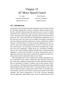
III. DIRECT TORQUE CONTROL OF PERMANENT MAGNET SYNCHRONOUS MOTOR The torque of the permanent magnet synchronous motor is controlled by inspecting the armature current since electromagnetic torque is directly proportional to the armature current. For high dynamic performance, the current control is applied on rotor flux (dq) reference system which is rotated at synchronous speed. The main operating principle of DTC depends on selection of appropriate voltage vectors according to stator magnetic flux, difference between the values of reference and real torque. Fig. 1 shows the diagram of the DTC scheme for PMSM.
ON Devices
State No.
T1 T6 T2 T1 T3 T2 T4 T3 T2 T4 T3 T5 T4 T6 T5 T1 T6 T5 T1 T3 T5 T4 T6 T2
1 2 3 4 5 6 7 8
Sa 1 1 0 0 0 1 1 0
Switch States Sb 0 1 1 1 0 0 1 0
Sc 0 0 0 1 1 1 1 0
B. Determination of voltage space vector The main principle of DTC is to determine correct voltage vectors using the appropriate switching table. This determination is based on the torque and stator magnetic flux hysteresis control. Stator magnetic flux can be calculated by using following equation,
s
s
s
qd (v qd Rs i qd )dt
Figure 1. Diagram of DTC drive system
A. Voltage source inverter (VSI) Voltage source converter or voltage-fed converters, as the name indicates, receive dc voltage at one side and converts it to ac on the other side. The basic function of an inverter is to change the dc input voltage to a symmetric ac output voltage of desired magnitude and frequency. Three phase voltage source inverter (VSI) are normally used for high power applications and can be operated as stepped wave inverter or a pulse width in an PMSM drive, it is operated on pulse width modulated mode so as to overcome the problems such as excessive motor losses, pulsating torque and increases harmonic content at lower speeds. All this is possible because of the development of the semiconductor devices having switching time in fraction of seconds. Fig. 2. shows the diagram of the voltage source inverter. Table I. gives the inverter switching states.
Once the stator flux is estimated, the torque produced can be calculated. The torque produced is dependent on the stator flux as well as rotor flux. Thus electromagnetic torque can be calculated in terms of the cross product of rotor flux and stator current and is given as, Te
3P 4
(d iq q id )
(7)
Hysteresis controllers consist of two level flux hysteresis comparator and three level torque hysteresis comparator. These are used to select the vector from the voltage vector selection table (Table II) which will drive the error between the estimated parameters and the reference values to zero. Table II. Voltage vector selection table SECTOR dλ
1
-1
Figure 2. Voltage Source Inverter (VSI)
(6)
dTe
1
2
3
4
5
6
1
u2
u3
u4
u5
u6
u1
0
u0
u7
u0
u7
u0
u7
-1
u6
u1
u2
u3
u4
u5
1
u3
u4
u5
u6
u1
u6
0
u7
u0
u7
u0
u7
u0
-1
u5
u6
u1
u1
u3
u4
Equation (7) shows that stator magnetic flux and the voltage space vector have the same direction. Therefore, stator magnetic flux’s amplitude and direction is controlled by means of keeping in specified bandwidth by using the correct voltage space vector. The voltage vector thus helps in controlling the stator magnetic flux amplitude depending on the switching table. The switching table is formed by dividing voltage vector plane into six sections as shown in fig. 3. Two adjacent voltage vectors that yields the lowest switching frequency are selected in order to increase or s decrease the amplitude of stator flux .
Figure 4. stator magnetic flux vector trajectory
Figure 5. Current response Figure 3. Vectors of space vector modulation
IV. SIMULATION RESULTS The MATLAB simulation results of DTC of the permanent magnet synchronous motor for different load is presented in this section. The parameters of motor are listed in Table III. For DTC, the band width of hysteresis comparator is set to zero. Figure 6. Dynamic torque response
Table III. Motor Parameters Number of pole pairs Output power Rated current Rated Torque DC bus voltage d-axis and q-axis inductance Stator resistance Permanent magnet flux Rated speed Inertia
3 3.0 HP 4.0 A 4.5 N-m 310 V 8.5 mH 1.8Ω 0.175 Wb 1500 rpm 0.002 Kg-m2
Fig. 4, fig. 5, fig. 6, fig. 7 and fig. 8 present the dynamic response of the DTC. The motor starts from standstill to rated speed at full load i.e. 4.5 N-m and then at t = 0.05 second load is reduced to 2N-m. It is seen that, when load on the motor is reduced the motor current and torque reduces whereas the speed of the motor increases by a 0.5 rpm for a fraction of second but it regains its synchronous speed since its been a property of PMSM to run at constant speed irrespective of the load.
Figure 7. Flux response
Figure 8. Speed response
Fig. 9, fig.10, fig. 11, fig. 12 presents the dynamic response of PMSM, after the motor has been started from standstill. The motor starts from standstill to rated speed at initial load of 2 N-m and then at t = 0.05 second load is increased to 4.5 N-m. In this case it seen that, when the load on the motor is increased the motor current and torque is increased while the speed of the motor is decreased by 0.5 rpm for fraction of second but it regain its synchronous speed
approached scheme. The controller used for tuning in simulation is PI controller that utilizes feedback speed data for speed control. Results show that stator magnetic flux vector fits in a circular flux orbit within the hysteresis band and torque response is also very fast. Also variation of load torque does not cause much of the variation on the speed of the motor. Thus it can be concluded that vector control is better if adapted (load variation) for PMSM as it also helps in yielding the response quicker. VI. REFERENCES
Figure 9. Current response
Figure 10. Dynamic torque response
Figure 11. Flux response
Figure 12. Speed response
V. CONCLUSION In this paper, main characteristic of the direct torque control scheme for PMSM drive is studied by simulation with a view to highlight the advantages and disadvantages of the
[1] Tian Shi Wang, Jian Guo Zhu, You Guang Guo,Gang Lei, Wei Xu, ―Simulation and Experimental Studies of Permanent Magnet Synchronous Motor Control Methods‖, Proceedings of 2011 IEEE International Conference on Applied Superconductivity and Electromagnetic Devices Sydney, Australia, December 14-16, 2011. [2] R. H. Park, ―Definition of an ideal synchronous machine and formula for the armature flux linkages,‖ General Electric Review, vol. 31, pp. 332, 1928. [3] Mohamed Kadjoudj, Soufiane Taibi, Noureddine Golea, Hachemi Benbouzid, ‖Modified Direct Torque Control of Permanent Magnet Synchronous Motor Drives‖, International Journal of Sciences and Techniques of Automatic control & computer engineering IJSTA, Volume 1, N° 2, December 2007, pp. 167−180. [4] Modern Power Electronics & AC Drives by B. K. Bose, 4th Edition, Phi Publication. [5] M. S. Merzoug and F. Naceri, ―Comparison of Field-Oriented Control and Direct Torque Control for Permanent Magnet Synchronous Motor (PMSM)‖, World Academy of science, Engineering and Technology 45 2008. [6] HRABOVCOV´A, V.—RAFAJDUS, P.—FRANKO, M.— HU-DAK, P. : Measurements and Modeling of Electrical Machines, EDIS publisher of University of ˇ Zilina, 2004. (in Slovak) [7] FRANKO, M.—HRABOVCOV´A, V.—HUD´AK, P. : ―Measurement and Simulation of Permanent Magnet Synchronous Machines‖, XI. International Symposium on Electric Machinery in Prague, ISEM 2003, 10–12 September 2003. [8] Özçıra, S.: ―Control methods and industrial applications of permanent magnet synchronous motors”. M.S. Thesis, Advisor: Bekiroglu, N. Asst.Prof., Yildiz Technical University, Istanbul (Turkey), 2007. [9] Minoru, K.: ―Application of permanent magnet synchronous motor to driving railway vehicle”s. RailwayTechnology Avalanche, vol.1. no.1. 2003, pp. 6. [10] J.O.P.Pinto,B. K. Bose, L. E. B. Silva, M. P. Kazmierkowski, ―A neural-network-based space-vector PWM controller for voltage-fed inverter induction motor drive,‖ IEEE Transactions on Industry Applications, vol. 36, no. 6, Nov./Dec. 2000, pp. 1628–1636.