MOHAMED MENAA. 1. , OMAR TOUHAMI. 2. , RACHID IBTIOUEN. 2 and MAURICE FADEL. 3. 1. Laboratoire de Robotique Parallélisme et Electro-énergétique, ...
Proceedings of the 6th WSEAS International Conference on Power Systems, Lisbon, Portugal, September 22-24, 2006
261
Speed Sensorless Induction Motor Control using Extended Complex Kalman Filter and Spiral Vector Model MOHAMED MENAA1, OMAR TOUHAMI2, RACHID IBTIOUEN2 and MAURICE FADEL3 Laboratoire de Robotique Parallélisme et Electro-énergétique, Département d’Electrotechnique Université des Sciences et de la Technologie Houari Boumediene BP.32 EL Allia, Alger, 16111 Algérie. 2 Département de Génie Electrique Ecole Nationale polytechnique 10 AV Pasteur, El-Harrach, Alger Algérie. 3 Laboratoire d’Electrotechnique et d’Electronique Industrielle ENSEEIHT Toulouse, 2 Rue Camichel BP 7122 - 31071 Cedex7, France.
1
Abstract: - In this paper the authors develop a new method to vector control of the airgap flux machine with only two sensors (one for stator voltage and one for stator current) without Park transformation and without speed sensor. This method is based on the spiral vector theory for modeling the induction motor and the extended complex Kalman filter “ECKF”, which is the variant of the extended Kalman filter in the group complex for estimating the rotor speed. The simulation tests show the effectiveness of the proposed method under the noise variation and load torque variation. Key-Words: - Induction machine, Extended complex Kalman filter, Spiral vector theory, Estimation parameters, Sensorless control and Sonsorless direct airgap flux orientation control.
1 Introduction For high dynamic performance of an induction motor drive the vector control is used [1]. Speed transducers such as shaft mounted tachogenerators, resolvers, or digital shaft position encoders are commonly used to achieve the control of speed, torque and flux of induction motor in many industrial applications. However, in some cases it is difficult (e.g. a compact drive system) or extremely expensive, (e.g. submarine applications) to use sensors for speed measurement the mechanical sensor also reduces the robustness of drive and together with the cost of the hardware, causes additional expenses. Ongoing research has concentrated on the elimination of the speed sensor at the machine shaft without deteriorating the dynamic performance of the drive control system [2]. Speed estimation is an issue of particular interest with induction motor drives where the mechanical speed of the rotor is generally different from the speed of the revolving magnetic field. The advantages of speed sensorless induction motor drives are reduced hardware complexity and lower cost, reduced size of the drive machine, elimination of the sensor cable, better noise immunity, increased reliability and less maintenance requirement. The operation in
hostile environments mostly requires a motor without speed sensor [2]. To replace the speed sensor, the information on the rotor speed is extracted from measured stator voltages and currents at the motor terminals. Generally we use four or six sensors for measuring the stator voltages and currents that are necessary for Park transformation. In this paper the authors show that it is possible to develop a new sensorless airgap flux orientation control of an induction motor without Park transformation and with two sensors one for stator voltage and one stator current. The reduction in voltage and current sensor number augmented the advantages of the sensorless control as mentioned above. To be able to make the vector control of an induction motor with two sensors only, the authors propose to use the spiral vector theory for modeling the induction motor in both steady and transient state. The obtained model only depends on variables and parameters of one phase of stator and one phase of rotor, see the model order is reduced from six equations (three for the stator and three for the rotor) to a pair complex equations (one for stator and one for rotor) without matrix coordinate transformation.
Proceedings of the 6th WSEAS International Conference on Power Systems, Lisbon, Portugal, September 22-24, 2006
The instantaneous magnitude and position of the machine flux must be precisely known to achieve high dynamic performance in field orientation control. There are the various types of methods and algorithms used to estimate the magnitude and position of airgap flux. In this paper we propose to estimate the shaft speed and airgap flux by the extended complex Kalman filter “ECKF” based on the developed model. The ECKF is more attractive than the real one from the point of view of modeling and stability consideration for more details about ECKF see [3]. This paper is organized in four sections. In the first section the induction motor by spiral vector theory is developed. The second section proven the application of spiral vector model to the airgap flux orientation control. In the last section, the computer simulation tests under different scenarios (variation of the load torque, mechanical and electrical parameter variation and speed reference variation) are given to show the effectiveness of the proposed method.
2
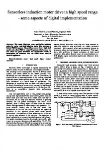
In Fig.1 when λ = 0 , “i” becomes a circular vector on the complex plane, which corresponds to steady state alternating current quantity. When ω = 0 , it expresses a decaying direct current quantity. When δ = 0 , it expresses a steady dc quantity. Thus the spiral vector can express almost all kinds of variables which appear in electrical engineering.
2.2 Induction motor model Generally the spiral vector theory is used to describe the model by transfer function [4][6][7]. In this paper we use this theory to develop a state space model. Assuming that the stator and rotor windings are electrically and magnetically symmetrical, the air-gap is uniform, the field distribution is sinusoidal, and neglecting the effects of magnetic saturation, eddy current and hysteresis. The induction motor is represented by the three phase stator and rotor windings not by the D.Q windings Fig. 2. The following per phase voltage equations arise: va
Induction Motor Model by Spiral Vector Theory
θ
ia a ωm
2.1 Spiral vector theory The spiral vector theory is an exponential time function with a complex index. It can express almost all kinds of state variables, which appear in electrical engineering, and is the most natural form solutions of circuit equations of electric circuits and performance equations of electrical machine. Both steady and transient state solutions can be expressed by spiral vectors. When spiral vector expressions are used, the steady state theory and transient state theory of AC circuit, which have been separated because of different expressions of state variables, are unified. Both steady state and transient state analyses of AC machines become simpler and easier [4] [5]. The spiral vector variable can be expressed in the following form: i = Ae δt with δ = −λ + jω , λ ≥ 0, ω ≥ 0, A = A e jϕ (1) As the time goes on, variable “i” depicts a spiral on the complex plane, Fig.1.
262
r ir it t b
is
s
c
ib vb
ic vc
Fig. 2. Three phase stator and rotor windings distribution of an induction machine. d λ ga ⎧ di a + ⎪V a = R 1 i a + l 1 dt dt ⎪ ⎨ ⎪ d λ gr di r ⎪0 = R 2 ir + l 2 + dt dt ⎩
(2)
The stator and rotor fluxes equations are as follow: ⎛ 2π ⎞ ⎛ 2π ⎞ λga = Laia + M s ib cos⎜ ⎟ + M sic cos⎜ − ⎟+ ⎝ 3 ⎠ ⎝ 3 ⎠ 2π ⎞ 2π ⎞ ⎛ ⎛ M rs ir cos(θ ) + M rsis cos⎜θ + ⎟ ⎟ + M rs it cos⎜θ − 3 ⎠ 3 ⎠ ⎝ ⎝ ⎛ 2π ⎞ ⎛ 2π ⎞ λgr = Lr ir + M r is cos⎜ ⎟ + M r it cos⎜ − ⎟+ ⎝ 3 ⎠ ⎝ 3 ⎠ 2π ⎞ 2π ⎞ ⎛ ⎛ M rsia cos(θ ) + M rsib cos⎜θ + ⎟ ⎟ + M rsic cos⎜θ − 3 3 ⎠ ⎠ ⎝ ⎝
(3)
(4)
The stator and rotor currents of symmetrical spiral vector are: δt
Fig. 1. Spiral vector in the complex plane.
i a = A1 e , ib = A1 e
2π ⎞ ⎛ ⎜ δt − j ⎟ 3 ⎠ ⎝
i r = A2 e δ 't , i s = A2 e
, ic = A1 e
2π ⎞ ⎛ ⎜ δ 't − j ⎟ 3 ⎠ ⎝
2π ⎞ ⎛ ⎜ δt + j ⎟ 3 ⎠ ⎝
, it = A2 e
2π ⎞ ⎛ ⎜ δ 't + j ⎟ 3 ⎠ ⎝
(5) (6)
Proceedings of the 6th WSEAS International Conference on Power Systems, Lisbon, Portugal, September 22-24, 2006
Replacing (5) and (6) in the fluxes expressions, obtain: M ⎤ 3 ⎡ λ ga = ⎢ La + s ⎥i a + M rs i r e jθ 2 ⎦ 2 ⎣ M ⎤ 3 ⎡ λ gr = ⎢ L r + r ⎥i r + M rs i a e − jθ 2 ⎦ 2 ⎣ Introducing (7) and (8) in (2), we obtain: ⎧ d 1 ⎤d 3 d ⎡ jθ ⎪⎪v1 = R1ia + l 1 ia + ⎢La + M s ⎥ ia + M rs ir e dt 2 ⎦ dt 2 dt ⎣ ⎨ d 1 d 3 d ⎡ ⎤ ⎪0 = R2ir + l 2 ir + Lr + M r ir + M rs iae− jθ ⎢ ⎪⎩ dt 2 ⎥⎦ dt 2 dt ⎣
we
As airgap flux orientation requires that Re Φ 0 = Φ 0 and ImΦ 0 = 0 , (12) and (13) become:
(7)
⎧ ⎛d ⎞ ⎛d ⎞ ⎪⎪v1 = R1 i1 + l 1 ⎜ dt + jω s ⎟i1 + ⎜ dt + jω s ⎟ Re(Φ0 ) ⎝ ⎠ ⎝ ⎠ (14) ⎨ d d ⎛ ⎞ ⎛ ⎪0 = R2′ i 2 p + l ′2 ⎜ + jω sl ⎟i 2 p + ⎜ + jω sl ⎞⎟ Re(Φ 0 ) ⎪⎩ ⎝ dt ⎠ ⎝ dt ⎠ 3 Τ em = P Re(Φ 0 )Im(i1 ) (5) 2 We consider the airgap flux and the rotor speed as reference, so we obtain the following airgap flux orientation equations: ⎧ ⎪ 2 1 Τemref ⎪Im(i1 ) = 3 P Φ0ref ⎪ ⎪⎪ l′ d σ d 1 l′ 2 Φ0ref + 3 Φ0ref + 2 ωsl Im(i1 ) Re(i1 ) + Re(i1 ) = ⎨ R2′ dt M R2′ ⎪ R2′ dt 2 ⎪ d l′2 Im(i1 ) + R2′ Im(i1 ) ⎪ ⎪ωsl = dt σΦ0ref − l′2 Re(i1) ⎪⎩
(8)
( )
(
)
(9)
With: θ = ω m t The obtained model (9) by spiral vector theory can represent the induction machine in any reference frame. This model contains only variables and parameters of one stator phase “a” and one rotor phase “r”, which are segregated from the other phases. In opposition to Park model where the voltages and the currents of two phases have to be known, the spiral vector model only needs the voltage and the current of one phase to achieve a vector control [9][8][10].
3 Airgap Flux Orientation Control The air gap flux orientation control based on the spiral vector model consists of choosing a model in the reference frame attached to the revolving field, the air gap flux vector Φ 0 is aligned with the real axis in order to achieve, as in a separately excited dc machine, decoupling control between the flux and the produced torque [5][8]. The torque is then controlled by the imaginary part of the stator current of the phase “a”. At the same time, the flux is controlled by the real part of the stator current of the phase “a”, called the flux producing current [5][8]. To obtain the model in the reference frame fixed in the revolving field, we set: i a = i1 e jθ s (10)
i r = i 2 e jθ sl
(11)
With: θ sl = θ s − θ We replace (10) and (11) in the (9), we obtain the model referred to the revolving field with Φ 0 =
(
)
3 i1 + i 2 p . 2
⎛d ⎞ ⎛d ⎞ ⎧ ⎪⎪v 1 = R1 i1 + l 1 ⎜⎝ dt + jω s ⎟⎠i1 + ⎜⎝ dt + jω s ⎟⎠Φ 0 ⎨ ⎪0 = R ′ i + l ′ ⎛⎜ d + jω sl ⎞⎟i + ⎛⎜ d + jω sl ⎞⎟Φ 2 2p 2 2p 0 ⎪⎩ ⎝ dt ⎠ ⎝ dt ⎠ 3 Τ em = P Im(i1Φ 0∗ ) 2
263
(12)
(13)
(16)
⎧ ⎪ω s = ω sl + ω m ⎪⎪ d d ⎨Re(v1 ) = l 1 Re(i1 ) + Φ 0ref + R1 Re(i1 ) − l 1ω s Im(i1 ) dt dt ⎪ ⎪Im(v ) = l d Im(i ) + R Im(i ) + ω l Re(i ) + Φ 1 1 1 1 1 s 1 1 0ref dt ⎩⎪ (17)
(
)
In most applications, speed sensors are necessary and essential in speed control loop. However sensors have several disadvantages in terms of drive cost, reliability, and noise immunity [2]. Several papers deal with the speed estimation. The most used in the last decade is the EKF, but generally these papers treat the speed estimation. In this paper we present for the first time the simultaneous estimation of the airgap flux, and rotor speed by the ECKF in the direct airgap flux orientation control.
4
ECKF Algorithm For State And Parameter Estimation
The ECKF is a variation of nonlinear Kalman filter in the complex form. It has been shown in Ref [3] that the ECKF is more attractive than the real one “EKF” from the point of view of modeling and stability consideration. The ECKF is more used in the power system estimation [11][12] but not in electrical machine estimation. The Kalman filter algorithm and its extension are a special kind of observer that provides
Proceedings of the 6th WSEAS International Conference on Power Systems, Lisbon, Portugal, September 22-24, 2006
optimal filtering of the noises in measurement and inside the system if the covariances of these noises are known. The system and measurement noise disturbances are white and Gaussian probability distribution. When the Kalman filter is used, the state space model of an induction machine in the stator reference frame is required; for obtaining the model in stator reference we put i1 = ia , i 2 = i r e jθ and v1 = v a in (9), thus obtaining the following induction machine model in the stator reference frame: d 3 d ⎧ ⎪⎪v1 = R1i1 + (l1 + L1 ) dt i1 + 2 M dt i2 (18) ⎨ ⎞ 3 ⎛d ⎞ ⎛d ⎪0 = R2i2 + (l 2 + L2 )⎜ − jωm ⎟i2 + M⎜ − jωm ⎟i1 ⎝ dt ⎠ 2 ⎝ dt ⎠ ⎩⎪ After all treatment and simplification, we obtain the following state space model of an induction machine in the stator reference frame, which is a function of the airgap flux. ⎧ X& e (t ) = Ae X e (t ) + BeU (t ) (19) ⎨ ⎩Ye (t ) = C e X e (t ) ⎡i ⎤ Where, X e (t ) = ⎢ 1 ⎥ , Y e (t ) = i 1 and U (t ) = v 1 , ⎣Φ 0 ⎦ ⎡ 1 ⎤ ⎢l ⎥ Ae12 ⎤ ⎡A ⎢ T' ⎥ and C e = [1 0 ] , B = Ae = ⎢ e11 e ⎥ A A ⎢ l2 ⎥ e 22 ⎦ ⎣ e 21 ⎢l σ ⎥ ⎣ T ⎦
With:
A e 11 =
(
− R 1σ + R 2' − j l '2 ω m l 1σ + l '2 R 2' 3 2 M
A e 12 = A e 21 =
R 2'
σ
−
m
A e 22 = l '2 3 M 2
⎞ l RT l ⎛ l ⎜−1+ ⎟ω m + j ⎜ l T σ ⎟⎠ σl T σ ⎝ ' 2
' 2
m
⎛ l '2 ⎞ ⎟ ⎜−1+ ⎜ l T σ ⎟⎠ σ ⎝ l' R' + 1, l T = l 1 + 2 and R T = R 1 + 2
σ
σ
The discrete time varying model is deduced from the continuous model by applying the Euler formula (first order). It is given by: ⎧ X e (k + 1) = AeD X e (k ) + BeDU (k ) (20) ⎨ ⎩Ye (k ) = C eD X e (k + 1) With: t = kT , AeD ≈ I + Ae T , C eD = C e BeD ≈ Be T . k
⎧ X e ( k + 1) = AeD X e ( k ) + B eD U ( k ) + W ( k ) ⎨ ⎩Y e ( k ) = C eD X e ( k + 1) + V ( k )
(21)
The state noise W and measured noise V can be any combination of harmonics and complex Gaussian white noise with zero-mean and variances σ w2 and σ v2 respectively. Real and imaginary parts of W (k ) are mutually independent and have the same variance, i.e. 2 2 2 2 σ w2 = σ wr + σ wi and σ wr = σ wi . We proceed in the same way forV(k) . The ECKF allows simultaneous estimation of complex states and rotor speed. The rotor speed is considered as extra state in an augmented state vector. This augmented model is non-linear because of multiplication between states. Thus, it must be linearized along the state trajectory to give a linear perturbation model. An extended induction machine model results if the rotor speed is included as additional state variable. The extended model can be expressed as follows: ⎧ξ ( k + 1) = f (ξ ( k ), U ( k ), k ) + W ( k ) (22) ⎨ ⎩η ( k ) = H ( k )ξ ( k ) + V ( k ) With: ⎡ A X ( k ) + B ed U ( k ) ⎤ f (ξ ( k ), U ( k ), k ) = ⎢ eD e ⎥ Ω m (k ) ⎣ ⎦
Then, linearizing the above system around the states and applying an ECKF, we obtain a nonlinear recursive filter based on the ECKF for estimating a complex state and parameters of an induction machine as follows:
(23a)
t
' 2
R − j σω M
3 2
To take into account the system uncertainties and disturbances, the following stochastic model is introduced:
Prediction of state ξ (k + 1) = f [ξ (k ), U (k ), k ] Estimation of error covariance matrix
l 1 σ + l '2
' 2
σ =
− j σω
)
264
P (k + 1) = A(k ) P (k ) A* (k ) + Q Kalman filter gain t t K = P(k + 1) H * (k ) ⎡ H (k ) P(k + 1)H * ( k ) + R ⎤ ⎢⎣ ⎥⎦ State estimation ξ (k + 1) = ξ (k + 1) + K [ y (k ) − H (k )ξ (k )] Update of the error covariance matrix P (k + 1) = P(k + 1) − KH (k ) P (k + 1)
⎡ H ( k ) = ⎢ C eD ⎣ A( k ) =
(23b) −1
(23c) (23d) (23e)
⎤ ∂ (C eD X e ( k ) )⎥ ∂Ω m ⎦
⎡ ∂f A (k ) = ⎢ eD ⎢ ∂ξ ⎣ 0
∂ ( AeD X e ( k ) + B eD X e ( k ) ) ⎤ ⎥ ∂Ω m ⎥ I ⎦
Where: y (k ) represents the measured *: conjugate, t: transpose, I: unit matrix.
current
Proceedings of the 6th WSEAS International Conference on Power Systems, Lisbon, Portugal, September 22-24, 2006
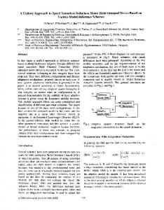
5 Simulation Results The simulation results tests were carried out using the direct airgap flux orientation control scheme of Fig. 3 without any speed measurement. The control is realized when we track one voltage and one current without any geometric transformation to the opposite of vector control based on the D.Q model where it’s necessary to track two voltage ( v as and v bs ) and two current ( ias and ibs ) to apply Park transformation. To test the performance of the proposed control, the simulations were performed on an induction machine with the sampling time T=0.1ms. Fig.3 shows different scenarios used to test the performance of the estimation and control algorithm under load torque variation, and system noise and measurement noise variation. In the first part, 0 ≤ t ≤ 1.25 , the simulation test between zero speed to 125rad/s under a load torque of 5Nm from standstill to 2s. We note that the rotor speed and airgap flux are not affected by the load torque and track its reference, the electromagnetic torque tracks its reference with little undulations caused by the noise variation. In the second part, 1.25s ≤ t ≤ 2.5s , the simulation test in the field weakening range under load torque is shown, the estimated rotor speed and estimated airgap flux are not affected by the torque and noise variation with small error between the estimated rotor speed and the real rotor speed, the electromagnetic torque tracks the reference quickly. In the third part, 2.5s ≤ t ≤ 4.5s , the simulation at low speed is shown and at t = 3.5s the load torque (10Nm) is applied to the motor shaft. We note that the estimated rotor speed track there reference quickly with small error between the estimated rotor speed and real rotor speed and the estimated airgap flux tracks its reference with small undulation. In the last part, inversion speed test (-125rad/s) under load torque (10Nm) is shown. We note that all variables track their references quickly and are not affected by the load torque and also are not affected by the noise variation. These results show that the ECKF and the direct airgap flux orientation control achieve a small speed error and also give stable airgap flux response. The obtained results show that the expected performance is attained.
6 Conclusion This paper shows that it is possible to release the direct airgap flux orientation control of the induction motor by only two sensors to the opposite of the vector control based on the D.Q model where it is necessary to use four or six sensors for park transformation. This result is possible only when we use the spiral vector theory
265
model. Also this paper has presented a new nonlinear filter “ECKF” for rotor speed estimation. The performances of the ECKF algorithm and direct airgap flux orientation control are tested for different scenarios obtained by applying step and linear variation to the rotor speed reference with load torque, noise variation. The performances observed of the system are satisfactory under step type variation and reversal of the load torque and step/linear changes and reversal in the rotor speed. Acknowledgements: This paper enters in the setting of a cooperation agreement international CMEP-Tassili under the 05MDU662 code.
References: [1] W. Leonarhd, Microcomputer control of high dynamic performance ac drives a survey, Autoamtica, vol 22, 1986, pp.1-19. [2] J. Holtz, Sensorless control of induction motor drives, a survey paper, Proceedings of IEEE, vol.90, n°8, 2002, pp.1359-94. [3] K. Nishiyama, A nonlinear filter for estimating a sinusoidal signal and its parameters in white noise: on the case of a single sinusoid, IEEE Transaction on Signal Processing, vol 45, n°4, 1997, pp. 970981. [4] S. Yamamura, Spiral Vector Theory of AC Circuits and Machines, Oxford, Clarendon Edition, 1992. [5] M. Menaa, Modeling and analysis of electrical machines by spiral vector theory, Master thesis, USTHB, 1997. [6] B.P Muni, S.K.Pillai, & S.N. Saxena, A PC based internal power factor angle controlled interior permanent magnet synchronous motor drive, Proceeding of IEEE-PECS, 1996, pp. 931-937. [7] M.L. DeAguiar, & M.M. Cad, The concept of complex transfer function applied to the modelling of induction motors. Proceedings of IEEE, 2000, pp. 387-391. [8] M. Menaa, O. Touhami, R. Ibtiouen, & R. Iung, Vector control induction motor by spiral vector theory, Proceedings of IEEE CCA, Trieste, Italy, 1998, pp.1265-1270. [9] M. Menaa, O. Touhami, & R. Ibtiouen, Identification of Induction Motor by Tacking Account of Spiral Vector Theory, Proceedings of IEEE-SDEMPED, Grado, Italy, 2001, pp. 283-287. [10] M. Menaa, O. Touhami, & R. Ibtiouen, Estimation of rotor resistance of an induction motor using extended Kalman filter and spiral vector theory, Proceedings of IEEE CCA, Istanbul, Turkey, 2003, pp. 1262-1266.
Proceedings of the 6th WSEAS International Conference on Power Systems, Lisbon, Portugal, September 22-24, 2006
[11] P.K. Dash, A.K. Pradhan, & G. Panda, Frequency estimation of distorted power system signals using extended Kalman filter, IEEE Transaction on Power Delivery, vol 14, n°3, 1999, pp 761-766.
266
[12] R.A. Flores, I.Y.H. Gu, & B M.H.J.ollen, Positive and negative sequence estimation for unbalanced voltage dips, Proceedings of IEEE, 2003, pp. 24982502.
Fig. 3. Sensorless direct airgap flux orientation control. 300
30 Machine electromagnetic torque Reference electromagnetic torque
Rotor speed Reference speed Estimated speed
250
25
20
Electromagnetic torque (N.m)
200
Rotor speed (rad/s)
150
100
50
0
-50
10
5
0
-5
-10
-100
-150
15
-15
0
1
2
3
4
5
6
-20
7
0
1
2
3
4
5
6
7
time (s)
time (s)
4
1.2
3
1
2
Airgap flux (Wb)
Rotor speed error (rad/s)
0.8
1
0
Estimated airgap flux (magnitude) Reference airgap flux (magnitude) Machine airgap flux (magnitude) Estimated airgap flux (imaginary part) Machine airgap flux (imaginary part)
0.6
0.4
-1 0.2
-2
0
-3
-4
0
1
2
3
4
5
6
7
-0.2
0
1
2
3
4
time (s)
time (s)
Fig.4. Simulation test results.
5
6
7