International Journal of the Physical Sciences Vol. 6(30), pp. 6820 - 6828, 23 November, 2011 Available online at http://www.academicjournals.org/IJPS DOI: 10.5897/IJPS11.468 ISSN 1992 - 1950 ©2011 Academic Journals
Full Length Research Paper
Stress-strain modelling of reinforced concrete membrane structures Ahmed H. Alwathaf1*, Aidy Ali2, Mohd S. Jaafar3 and Mohd A. Algorafi1 1
Department of Civil Engineering, Faculty of Engineering, Sana’a University, Sana’a, Yemen, P. O. Box 12544, Malaysia. 2 Department of Mechanical Engineering, Universiti Putra Malaysia, 43400 Serdang, Selangor, Malaysia. 3 Department of Civil Engineering, Universiti Putra Malaysia, 43400 Serdang, Selangor, Malaysia. Accepted 1 November, 2011
In this study, a nonlinear finite element (FE) model is proposed to investigate the behaviour and failure mechanism of reinforced concrete membrane structures. Proven accurate stress-strain relation is incorporated in the model to describe the stress-strain behaviour of the concrete under compression for uniaxial and biaxial stress system. The nonlinearity behaviour of the materials in the compressive stress field is considered for the concrete in the orthogonal directions. The effect of micro cracking confinement and softening on the stress-strain relationship under biaxial stresses are included by employing the equivalent uniaxial strain concept. Tension stiffening effect by concrete in tension is modelled in the ascending and descending parts. The model allows for the progressive local failure of the reinforced concrete materials. The applicability of the proposed FE model is investigated by demonstrating the nonlinear structural response and failure mechanism of a simple deep beam and validated with published experimental work. Good agreement is achieved between the developed FE model and the experimental test results which gives confidence that the approach is fundamentally correct. Key words: Reinforced concrete, nonlinear finite element analysis, strut, tie. INTRODUCTION Membrane structures are widely used in many applications such as in bunkers, water tanks, vertical diaphragms in bridges, retaining walls, silos, multistoreyed buildings, etc. The behaviour of reinforced concrete membrane structures is more complicated due to the nonlinear behaviour even in the elastic range which in turn makes the standard analysis and design methods ineffective for deep beams. These problems become extremely difficult in the inelastic range and mainly at the ultimate strength and overall collapse. In the last decades, finite element studies incorporating nonlinear material models have been vigorously used to determine the mechanics behaviour and to exploit the full
*Corresponding author: E-mail:
[email protected],
[email protected]. Tel: 00967 777 219 692. Fax: 00967 1 464 368.
potentialities of reinforced concrete membrane elements. In these models, more realistic nonlinear properties have been incorporated based on experimental investigation (Vecchio and Collins, 1986; Hsu, 1Huang 988; Hsu, 1991; Zhu et al., 2001). Those studies have, in turn, led to the development of rational design models based on the strut and tie approach for the design of membrane elements (Rogowsky and Macgregor, 1986; Rogowsky, 1997; Zhang and Tan, 2007; Bakir and Boduroglu, 2005). The strut and tie model has been used in analysis and design of disturbed regions, beam strengthened with FRP and infill frames and walls in masonry and reinforced concrete structures (Kuo et al., 2010; He and Liu, 2010; Shah et al., 2011; Colotti and Swamy, 2011; Seim and Pfeiffer, 2011; Baran and Sevil, 2010; Güney and Kurusçu, 2011). Despite of the large amount of research carried out on reinforced concrete membrane structures, there is no agreed rational procedure to predict the strength of these structures. This is mainly because of the very complex
Alwathaf et al.
25
6821
CONCRETE MATERIAL MODELLING
C o m pres s iv e s tre s s N/m m 2
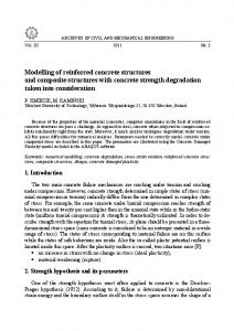
Stress-strain relation Using stress-strain relationship that can be described accurately, the behaviour of the concrete material is essential to predict the actual strength and deformation of the structure. In this study, the best fit equation of the experimental data of concrete material under uniaxial compression test for both ascending and descending parts is adopted (Carreira and Chu, 1985; Popovics, 1973). It can be expressed as:
20
15
10
σ= Saenz's Eq
5
Eq.1 Test results [8]
0 0
0.0005
0.001
0.0015
0.002
0.0025
0.003
0.0035
Strain mm/mm Figure 1. Comparison of test data and the best fit relation.
mechanism associated with the mode of failure of these structures. Development of a model to simulate the reinforced concrete membrane structures behaviour taking into consideration the accurate modelling for the biaxial stress-strain behaviour for the concrete is essential to understand the structural behaviour and failure mechanism of the system. Even though a lot of effort will be paid in the micro-modelling level, yet this procedure reveals more accurate results. In this study, a two-dimensional finite element model is proposed and an incremental-iterative program is developed to predict the behaviour and failure mechanism of the reinforced concrete membrane structures under inplane loading till failure. Detailed constitutive relationships are proposed for the finite element model. An accurate equation is used in the model to describe the nonlinear stress-strain behaviour of the plane concrete material under compression for the uniaxial and biaxial stress states. Material nonlinearity in the compressive stress field is considered in the orthogonal directions and the effect of micro cracking confinement and softening on the stress-strain relationship under biaxial stresses are included employing the equivalent uniaxial strain concept. Tension stiffening effect by concrete in tension is modelled in the ascending and descending parts. Moreover, the model allows for the progressive local failure of the materials such as crushing, cracking and yielding of reinforcing steel. After cracking, a smeared crack concept is adopted using fixed crack model and the compressive strength reduction in the cracked concrete is considered.
A(ε ε o )σ o A − 1 + (ε ε o ) A
(1)
where, σ , ε are the instantaneous values of the stress and the strain respectively; σo , εo, the ultimate stress (peak) and the corresponding strain, respectively and A, a coefficient called material parameter which depends on the shape of the stressstrain diagrams. In this study, nonlinear regression analysis has been used to determine the material parameter (A) using the entire stress-strain curve (ascending and descending part) obtained from compression test of concrete material. This procedure yields accurate values for this parameter compared to different methods derived based on the data at the origin (Carreira and Chu, 1985; Popovics, 1973). Equation 1 is capable of simulating the stress-strain relation for different concrete materials and can be incorporated efficiently in the biaxial stress model. Figure 1 shows the experimental test data of a compression test of concrete (Alwathaf, 2006) as well as the best fit curve drawn by Equation 1. A comparison with the wellknown formula suggested by Saenz (1964), which is frequently used for simulation of compressive stress-strain curves of concrete under biaxial stress state (Chen, 1982), is also shown in Figure 1. Unlike Equation 1, Saenz's formula fails to represent the variation of curvatures of the stress-strain relations for different concrete materials which in turn makes Saenz's equation more suitable for macro-modelling approach. Another condition that restricts using Saenz's formula is the ratio of the tangential modulus of elasticity at the origin to the secant modulus at the peak which should be more than or equal to 2. The concept of equivalent uniaxial strain was developed in order to allow actual biaxial stress-strain relationships to be duplicated from uniaxial relationship (Darwin and Pecknold, 1977). The equivalent uniaxial strain for any stress is the strain corresponding to the stress on the uniaxial loading curve. To include the biaxial stress effect on the uniaxial stress-strain relation given by Equation 1, the following procedure has been proposed to develop a more general expression to incorporate the biaxial effect. Rewriting Equation 1 in terms of equivalent uniaxial strain, εiu, we obtain (for i=1, 2):
σi =
A(ε iu ε ip )σ ip A − 1 + (ε iu ε ip ) A
(2)
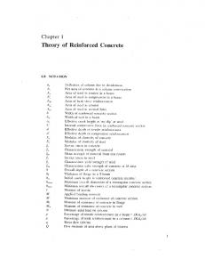
The equivalent uniaxial strain εiu essentially removes Poisson's effect; whereas the strengthening due to the microcracking confinement in biaxial compressive stress and softening in compression-tension stress fields are incorporated in σip and εip, respectively (Darwin and Pecknold, 1977; Ayoub and Filippou, 1998). Thus a single relation (Equation 2) can represent the infinite variety of monotonic biaxial loading curves (Figure 2). The strength is reduced when α < 0.0 whereas for α > 0.0, the strength is enhanced due to microcracking confinement. The maximum stress (peak), σip, and the corresponding strain εip will be found from the
6822
Int. J. Phys. Sci.
-σi σip σip=fc' α > 0.0 Eq.2
α=0.0 α < 0.0
εcr - εiu Eq.5
εo εip
feq Eq.4
Figure 2. Stress-strain relationship of concrete material in compression and tension.
f 't/f σ1/f 'c 1.0
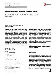
At the linear stage of tension stress, the slope is equal to the initial tangent modulus (Eo) at the origin. Figure 2 depicts the equivalent uniaxial stress-strain curves for concrete element loaded with different biaxial stress ratios, α, (α= σ1/ σ2) in the compression and tension fields. Failure criteria and constitutive laws The proposed failure envelope implements the biaxial strength envelope shown in Figure 3 for all stress states and summarized in Table 1. The principal stresses in two orthogonal directions are denoted by σ1 and σ2 with │ σ1│≤│ σ2 │ (negative sign (-ve) for compressive stress and strain). An incremental relationship is assumed between strains and stresses, which in differential form and in the principal directions can be written for undamaged concrete (Chen, 1982):
1.0 Implemented envelope Kupfer envelope (Kupfer and Gerstle, 1973)
σ2/f 'c
dσ1 1 dσ 2 = 2 dτ 1 −ν 12
Figure 3. Concrete material envelope for different stress states.
biaxial failure criteria. The tangent moduli E1t and E2t for a given principal stress are found as the slopes of the σ1 versus ε1u and the σ2 versus ε2u curves for the current ε1u and ε2u as follows:
Eit =
[
AEs A − 1 + (ε iu / ε ip ) A − A(ε iu / ε ip ) A
[A − 1 + (ε
iu
/ ε ip )
]
A 2
]
(3)
In the tension field, two relations are used for ascending and descending branches taking into account the tension stiffening of concrete (Hsu and Zhang, 1996; Wang and Hsu, 2001): σ1= Eo ε1 for ε1≤ ε
(4)
σ1= fcr (εcr/ ε1)0.4 for ε1> εcr
(5)
E1 ν E1E2 E2 ν E1 E2 0 0
dε1 . dε 2 (1 −ν 2 )Gdγ 12 0 0
(6)
where
v = v1v2
and v1=v2=0.2
G = 0.25( E1 + E 2 − 2ν E1 E 2 ) /(1 − ν 2 )
(7) (8)
where E1,v1 and E2,v2 are the tangent moduli of elasticity and the Poisson’s ratio along the principle stress directions and G is the shear modulus. The tangent moduli of elasticity, E1 and E2, along the principle stress directions are evaluated in the compressive field from a nonlinear equivalent uniaxial stress-strain relation based on Equation 3. In the tensile field, the initial modulus, Eo, is used in the linear part before cracking and the secant modulus, Eis= σi / εi, after cracking (Figure 2). The material stiffness matrix of cracked and crushed concrete is presented in Table 2. Instead of zeros, very
Alwathaf et al.
6823
Table 1. Failure criteria under different stress states.
Stress state
Criteria
K c1 = 1 + 0.92(σ 2 / f c′ ) − 0.76(σ 2 / f c′) Biaxial compression region (Vecchio,1992)
2
2 K c 2 = 1 + 0.92(σ 1 / f c′ ) − 0.76(σ 1 / f c′ )
σ1p= Kc1 f 'c σ2p= Kc2 f 'c
ε1p= Kc1εo ε2p= Kc2εo
σ1p= feq = 1 − (σ 2 / f c′ )2 f t′ Tension-compression region (Cerioni and Doinda, 1994)
σ2p= σ1p/α ≤ 0.65 f 'c ε1p= σ1p/Eo 3 2 ε2p= εo[-1.6q +2.25q +0.35q] q = σ2p/ f 'c
Tension-Tension Region (Lee et al., 2004)
σ1p= f't ≥ σ2p
Table 2. Material stiffness matrix of cracked and crushed concrete material.
Cracking in one direction
0 0 0 E 2 0 0
0 0 βG
Cracking in both directions
0 0 0 0 0 0 0 0 β G
Crushing
0 0 0 0 0 0 0 0 0
σ
=
1 ≤ 1.0 0 . 8 + 0 . 34 ( ε 1 / ε o )
(10)
where εo is the compressive strain relative to the uniaxial compressive strength, f 'c, and ε1 is the tensile strain normal to the crack direction. An incremental-iterative 2-D nonlinear finite element code is developed to implement the proposed constitutive model. Moreover, numerical procedure and solution algorithm are proposed to solve the nonlinear system. More details about the solution algorithm can be obtained elsewhere (Alwathaf, 2010).
MEMBRANE STRUCTURE DISCRETIZATION
(9a)
and β=0.2 for ε1 > εcr.
2 p
f c′
small values are substituted in the program to avoid singularity in stiffens matrices. Smeared fixed crack model is adopted in this study because it is capable of taking into account the concrete contribution, Vc (Zhu et al., 2001). After cracking, the tangential elasticity modulus and the Poisson's ratio are reduced to zero in the direction perpendicular to the crack direction but a reduced shear modulus, βG, is employed to simulate the aggregate interlock. The reduction is achieved by shear retention factor, β (Al-Manaseer and Phllips, 1987). Good results were obtained with the following shear retention factor: β=1.0 for ε1 ≤ εcr
after cracking can be significantly reduced by the tensile strain in the transverse direction. To account for this effect, the following formula is adopted to obtain σ2p after cracking (Vecchio and Collins, 1993):
(9b)
The concrete along cracks is still resisting compressive stress after cracking. It was found that the compressive strength of concrete
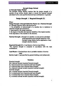
The developed FE model was used to predict the structural response of a full scale reinforced concrete simple deep beam subjected to uniform distributed load. The properties of the concrete and steel used in the FE model were obtained from an experimental investigation reported by Foster (1992). Figure 4a shows the dimensions, reinforcement, and loading details of the simple deep beam which is simulated in this study. Moreover, the material properties and parameters used in the finite element analyses for concrete and reinforcing steel are presented in Tables 3 and 4 respectively. The finite element mesh for the deep beam is depicted in Figure 4b. Eight-noded iso-parametric plane stress element is used to model the concrete characteristics and discrete two-noded isoparametric bar element is used to model the reinforcing bar. In the analysis of concrete deep beams, perfect bond was assumed between the reinforcement and the concrete. The stress-strain relationship for reinforcement was approximated by a bilinear function in which beyond yield point (fy), the plastic behaviour is reached and steel modulus Es is employed before yielding and Ep after yielding. The steel reaction plates were modelled using linear elastic plane stress element to transmit smoothly the reaction stresses to the concrete.
6824
Int. J. Phys. Sci.
(a)
(b)
Figure 4. Dimension and reinforcement arrangement (Foster, 1992) and idealization.
Table 3. Material properties and model parameters for concrete.
f'c (N/mm2) 29.6
Eo N/mm2) 22200
ν 0.2
A 2.8
εo 0.002
f 't (N/mm2) 2.18
Thickness (mm) 100
Table 4. Material properties for steel.
Bar size mm 5 8
2
Area mm ) 20 53
fy (MPa) 412.0 412.0
RESULTS AND DISCUSSION Figure 5 shows the load versus deflection at lower midspan point obtained from the finite element model and the experimental test results. The beam failed at a load of 1101 kN which is in agreement with the test result of 1171 kN. The discrepancy between the test and FE model results is about 6%. The model gives reasonably accurate predictions for the displacement especially at lower loads. At higher loads, the model shows higher stiffness until failure. This may have been caused by the geometric idealization of the beam or difficulty in the numerical solution process of the proposed constitutive relations. Another reason for the discrepancy between the test and FE model could be attributed to the type of failure of the beam in the experimental test as will be discussed subsequently.
Es (MPa) 2.06×10⁵ 2.06×10⁵
Ep (MPa) 5×10³ 5×10³
Contours of compressive stresses (σ2) for the finite element model are shown in Figure 6 at different loads (448, 640, 896, and 1101 kN). A compressed strut is developed clearly after concrete cracking (when the load is higher than 448 kN). As shown in the figures, the concrete strut transmitting the load to the support is clearly shown. At the same time, the steel reinforcing bars at the bottom act as a tie. Higher compressive stress occurred at the support region which is the bottom end of the strut and the stress became uniform at the middle and the top of the strut. As shown in Figure 6, the bandwidth of the strut is quite large and it becomes narrow at the middle due to the nature of loading and the aspect ratio of the beam. This is not identical to deep beams loaded with concentrated load which show relatively a small and uniform bandwidth all over the strut (Foster, 1998; Zhang and Tan, 2007). Therefore, for this
Alwathaf et al.
FE model Exp. test (Foster, 1992)
Figure 5. Load versus deflection at the midspan.
0
0
-2
-2
-4
-8 -10
-6
-12
-8
-14
-10
-16
-12
-18
-14
-20 -22
-16
-24
-18
-26
-20
-28
-22
-30
-24
-32 -34
-26
-36
-28
(a) 448 kN
-38
(b) 640 kN
0
0
-2.5 -5
-5
-7.5 -10
-10 -12.5
-15
-15 -20
-20 -25
-25
-30 -35
-30
-40 -35
-45 -50
-40
-55 -45
(c) 896 kN
-60
(d) 1101 kN
Figure 6. Compressive stresses distribution at different loads.
6825
6826
Int. J. Phys. Sci.
1800
1800
1600
1600
1400
1400
448 kN
1200
1200
1000
898 kN
800
1101kN
448 kN
Height
Height
640 kN
1000
640 kN
800
898 kN 1101kN
600
600
400
400
200
200 0
0 -0.0002
0
0.0002
0.0004 0.0006 0.0008
-0.001
0.001
-0.0008 -0.0006 -0.0004 -0.0002
x-strain
x-strain mm/mm Figure 7. Strain in x-direction along the wall height at mid-span.
0
0.0002
mm/mm
Figure 9. Strain in x-direction along the wall height near support.
1800
1800 1600
1600 1400
1400 448 kN
1200
Height
1000 640 kN
1101kN
1000
Height
448 kN
898 kN
1200
640 kN 898 kN
800
1101kN
800 600
600 400
400 200
200
0 -0.001
0 -0.001
-0.0008 -0.0006 -0.0004 -0.0002
0
0.0002
y-strain mm/mm
-0.0008 -0.0006 -0.0004 -0.0002
y-strain
0
0.0002
mm/mm
Figure 10. Strain in y-direction along the wall height near support.
Figure 8. Strain in y-direction along the wall height at mid-span.
type of deep beam, the width of strut at the middle should be taken for any design consideration when using strut and tie method. Figures 7 and 8 show the strains distribution in x and y directions (εx and εy) at mid-span along the height of the wall. As shown in the figures, nonlinear strain distributions along the height of the wall are realized in x and y directions. It can be seen that the strain (εx) inverted many times and multiple neutral axes were developed.
This proves that deep beams are a special case of the conventional beams and it is difficult to apply the conventional beam theory in this case. The strain distributions near the support along the wall height are also shown in Figures 9 and 10. Even though the bottom part of the beam near the support reached to the crushing failure (as will be shown later), it can be observed that the compressive strain is still less than crushing strain of the unaxial state (Table 3). This is because this part actually is under biaxial compression-tension stress and in this case, the tensile stress decreases the capacity of the
Alwathaf et al.
6827
simulation has been achieved for the structural behaviour of the simple deep beam. The model gives reasonably accurate prediction of the load carrying capacity, deformation and failure pattern of the beams. On the other hand, overestimation of stiffness of cracked concrete has been observed in the load-deformation curves. It can be concluded also that the reinforced concrete element under shear is actually subjected to a biaxial stress condition. The strength in the principal compression direction was found to be softened by the principal tension in the perpendicular direction and softened strut with varied bandwidth is developed. Moreover, the compressed strut is developed clearly after concrete cracking and failure is caused by crushing of the strut near the support. REFERENCES
(a) Crushing
(b) Cracking
Figure 11. Crushing and cracks pattern at failure.
the orthogonal compressed direction and developed softened strut (Bakir and Boduroglu, 2005). The predicted crushing and cracks pattern of the beam is shown in Figure 11. As shown in the figure, the failure of the finite element model was due the crushing of the concrete in the vicinity of the support. This is not consistent with the observed experimental results where the failure due to the crushing of the concrete at the support because of the specimen preparation (Foster, 1992). Because the studied beam can be considered as non-flexural member due to the aspect ratio, it did not fail by the yielding of steel at the bottom or crushing of concrete at the top in the mid-span and instead it failed by the crushing of compressed strut at the vicinity of the support. Conclusions A detailed micro-model for reinforced concrete membrane structures has been proposed. An effort has been paid to simulate the nonlinear stress-strain behaviour of the concrete materials in the orthogonal directions employing an accurate stress-strain relation for stress states and equivalent uniaxial strain concept. A finite element program code has been developed to implement the proposed model. The comparisons between the finite element analysis results with the experimental test show that a good
Al-Manaseer AA, Phllips DV (1987). Numerical study of some postcracking material parameters affecting nonlinear solutions in RC deep beams. Can. J. Civil. Eng., 14(5): 655-666. Alwathaf AH (2006). Development of Finite Element Code for NonLinear Analysis of Interlocking Mortarless Masonry System. Ph.D. Dissertation, University of Putra Malaysia, Malaysia. pp. 163-238. Alwathaf AH (2010). Nonlinear Finite Element Modelling of Reinforced Concrete Deep Beam. Struct. Concrete, 11(2): 63-72. Ayoub A, Filippou F (1998). Nonlinear finite element analysis of RC shear panels and walls. J. Struct. Eng. ASCE, 124: 298-308. Bakir PG, Boduroglu HM (2005). Mechanical behaviour and non-linear analysis of short beams using softened truss and direct strut. tie models. Eng. Struct., 27: 639–651. Baran M, Sevil T (2010). Analytical and experimental studies on infilled RC frames. IJPS, 5(13): 1981-1998. Carreira DJ, Chu KC (1985). Stress-Strain Relationship for Plain Concrete in Compression. ACI J., 82: 797-804. Cerioni R, Doinda GA (1994). Finite Element Model for the Nonlinear Analysis of Reinforced and Prestressed Masonry Wall. Comp. Struct., 53: 1291-1306. Chen WF (1982). Plasticity in reinforced concrete, McGraw-Hill Book Company, pp. 3-47. Colotti V, Swamy RN (2011). Unified analytical approach for determining shear capacity of RC beams strengthened with FRP. Eng. Struct., 33: 827–842. Darwin D, Pecknold D (1977). Nonlinear biaxial stress-strain law for concrete. J. Eng. Mech. ASCE, 103: 229-241. Foster S (1992). The Structural Behaviour of Reinforced Concrete Deep Beams. PhD Dissertation, University of New South Wales, Chap. 4 10-17. Foster S (1998). Design of Non-Flexural Members for Shear, Cem. Concr. Composites, 20: 465-475. Güney D, Kurusçu AO (2011). Optimization of the configuration of infill walls in order to increase seismic resistance of building structures. IJPS, 6(4): 698-706. He Z, Liu Z (2010). Optimal three-dimensional strut-and-tie models for anchorage diaphragms in externally prestressed bridges. Eng. Struct., 32: 2057-2064. Hsu T (1988). Softened truss model theory for shear and torsion. ACI Struct. J., 85(6): 624–635. Hsu T (1991). Nonlinear analysis of concrete membrane elements. ACI Struct. J., 88(5): 552–561. Hsu TT, Zhang LX (1996). Tension stiffening in reinforced concrete membrane elements. ACI Struct. J., 93 (1): 108-115. Kuo WW, Cheng TJ, Hwang SJ (2010). Force transfer mechanism and shear strength of reinforced concrete beams. Eng. Struct., 32: 15371546. Kupfer H, Gerstle K (1973). Behaviour of concrete under biaxial stresses. J. Eng. Mech. ASCE, 99: 853-867.
6828
Int. J. Phys. Sci.
Lee S, Song Y, Han S (2004). Biaxial Behaviour of Plain Concrete of Nuclear Containment Building. Nuclear. Eng. Design, 227: 143-153. Popovics S (1973). A numerical approach to the complete stress-strain curve of concrete. Cem. Concr. Res., 3(4): 583-599. Rogowsky D (1997). Strut and tie models. In proceeding of J.G. MacGregor Symposium, AC1 Convention, Seattle. Rogowsky DM, Macgregor JG (1986). Design of reinforced concrete deep beams. Concr. Inter., 8: 49-58. Saenz LP (1964). Discussion of “Equation for the stress-strain curve of concrete,” by Desayi and Krishnan, ACI J., 61: 1229-1235. Seim W, Pfeiffer U (2011). Local post-strengthening of masonry structures with fiber-reinforced polymers (FRPs). Construct. Build. Mater., 25: 3393–3403. Shah A, Haq E, Khan S (2011). Analysis and Design of Disturbed Regions in Concrete Structures. Procedia. Eng., 14: 3317–3324. Vecchio F (1992). Finite element modelling of concrete expansion and confinement, J Struct. Eng. ASCE, 118: 2390-2405. Vecchio F, Collins M (1986). The Modified Compression-Field Theory for Reinforced Concrete Element Subjected to Shear. ACI J., 83: 219-231.
Vecchio F, Collins M (1993). Compressive Response of cracked Reinforced Concrete. J. Struct. Eng. ASCE, 119: 590-610. Wang T, Hsu TC (2001). Nonlinear finite element analysis of concrete structures using new constitutive models. Comp. & Struct., 79: 27812791. Zhang N, Tan KH (2007). Direct strut-and-tie model for single span and continuous deep beams. Eng. Struct., 29(11): 2987–3001. Zhu RH, Hsu TT, Lee JY (2001). Rational shear modulus for smearedcrack analysis of reinforced concrete. ACI Struct. J., 98 (4): 443-450.