Article pubs.acs.org/JPCB
Structural and Electrochemical Properties of Succinonitrile-Based Gel Polymer Electrolytes: Role of Ionic Liquid Addition Mohd. Suleman, Yogesh Kumar, and S. A. Hashmi* Department of Physics and Astrophysics, University of Delhi, Delhi-110007, India ABSTRACT: Experimental studies on the novel compositions of gel polymer electrolytes, comprised of plastic crystal succinonitrile (SN) dispersed with pyrrolidinium and imidazolium-based ionic liquids (ILs) entrapped in a host polymer poly(vinylidine fluoride-co-hexafluoropropylene) (PVdF-HFP), are reported. The gel electrolytes are in the form of free-standing films with excellent mechanical, thermal, and electrochemical stability. The introduction of even a small content (∼1 wt %) of ionic liquid (1-butyl-1-methylpyrrolidinium bis(trifluoromethyl-sulfonyl)imide (BMPTFSI) or 1-ethyl-3methylimidazolium trifluoromethanesulfonate (EMITf) in the PVdF-HFP/SN system (1:4 w/w) enhances the electrical conductivity by 4 orders of magnitude, that is, from ∼10−7 to ∼10−3 S cm−1 at room temperature. The structural changes due to the entrapment of SN or SN/ILs mixtures and ion−SN−polymer interactions are examined by Fourier transform infrared (FTIR)/Raman spectroscopy, scanning electron microscopy (SEM), X-ray diffraction (XRD), and differential scanning calorimmetry (DSC). Various physicochemical properties and fast ion conduction in the gel polymer membranes show their promising characteristics as electrolytes in different ionic devices including supercapacitors.
■
so forth.16−21 Apart from these properties, the IL-based polymer electrolytes are not very cost-effective due to the consumption of the large proportion of ILs with an IL-topolymer ratio of more than 4:1 w/w. Recently, a few studies have been reported on the solid electrolytes including polymer-based electrolytes incorporating plastic crystalline materials, for example, most popularly succinonitrile (SN), which plays the role of solid-state solvent.22−27 The ionic conductivity values of SN-based electrolytes/polymer electrolytes/GPEs, when doped with various salts such as the salts of lithium, sodium, and so forth have been reported to be in the range of ∼10−4−10−3 S cm−1 at room temperature.22−29 The SN, in its crystalline phase, has two C2H4(CN)2 molecules per unit cell, and its plastic phase is stable for the temperature range from −40 to 58 °C.25−27 Below −40 °C, SN molecules exist in gauche conformation only, with an overall rigid monoclinic structure in which all of the rotatory motions are seized.30−32 The orientational disorder in the plastic phase of SN at room temperature is due to the coexistence of trans and gauche isomers. The trans isomers act as an impurity, resulting in the enhancement of lattice defects and hence the decrease in activation energy for fast ionic transport.30−32 This is also a reason for high polarity and hence high dielectric constant (about 55 at room temperature), which shows the ability of SN to dissociate the salts for high ionic conductivity to the larger extent as compared to the conventional organic solvents.22,30−34 Also in its trans−gauche isomer form, which involves rotation of molecules about the
INTRODUCTION There has been a continuous effort worldwide to develop solidstate electrolytes having fast ionic conductivity with acceptable thermal, mechanical, and electrochemical stability, so that they can replace their liquid counterparts in various ionic devices.1−9 These solid electrolytes are free from many limitations, for example, leakage, flammability, toxicity, and so forth associated with liquid electrolytes. Development of solvent-free polymer electrolytes is an approach that has been adopted to resolve these problems; however, room-temperature ionic conductivity of these electrolytes is low (10−6−10−5 S cm−1), and they do not provide proper electrode−electrolyte contacts.4−9 The gel polymer electrolytes (GPEs) are a recently developed class of polymer-based electrolytes. These electrolytes offer high ionic conductivity almost comparable to that of liquid electrolytes and have dimensional stability like solid electrolytes with substantial flexibility for proper electrode−electrolyte contacts. Most of the reported GPEs are comprised of liquid electrolyte solution of salts in organic plasticizers, for example, ethylene carbonate (EC), diethyl carbonate (DEC), propylene carbonate (PC), and so forth, immobilized in host polymers like poly(methyl methacrylate) (PMMA), poly(vinylidine-fluorideco-hexafluoropropylene) (PVdF-HFP), poly(ethylene oxide) (PEO), and so forth.4−9 In recent years, many polymer electrolytes/GPEs are reported that employ room-temperature ionic liquids (RTILs) to replace the plasticizers like EC, PC, etc.10−15 It may be noted that the neat ionic liquids (ILs) are also reported as promising electrolytes in various electrochemical systems.16−21 These electrolytes possess high thermal and electrochemical stability due to the special features of ILs such as nonvolatility, nonflammability, wider electrochemical window, high ionic conductivity, excellent thermal stability, and © 2013 American Chemical Society
Received: December 15, 2012 Revised: May 29, 2013 Published: May 30, 2013 7436
dx.doi.org/10.1021/jp312358x | J. Phys. Chem. B 2013, 117, 7436−7443
The Journal of Physical Chemistry B
Article
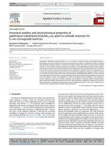
Figure 1. SEM images of (a) pure PVdF-HFP (scale bar = 10 μm), (b) 20% PVdF-HFP + 80% SN (w/w), (c,d) 20% PVdF-HFP + [(80 − x)% SN + x% BMPTFSI] for x = 1 and 5, and (e,f) 20% PVdF-HFP + [(80 − x)% SN + x% EMITf] for x = 1 and 5, respectively. The scale bar = 5 μm for (b−f).
ques such as scanning electron microscopy (SEM), X-ray diffraction (XRD), thermal analysis, vibrational (infrared and Raman) spectroscopy, cyclic voltammetry, and ionic conductivity measurements. It has been observed that the electrolytes PVdF-HFP/SN/ILs are mechanically stable and free-standing in the form of semitransparent films and possess excellent electrochemical properties. Although these polymerbased systems are not useful for rechargeable batteries due to the absence of Li+ and Na+, like target ions, these are primarily applicable as electrolytes in energy (charge) storage devices, namely, supercapacitors. Such systems have possible applications in all plastic electrochromic display devices and proton batteries also.
central C−C bond, the SN molecules help to increase the mobility of ions. Moreover, due to the plastic character (contrary to normal crystals), the SN-based electrolytes possess the ability to accommodate the mechanical stress, that is, volume changes resulting due to the ion switching at the electrode−electrolytes interfaces during electrochemical operations, and hence provide better electrode−electrolyte contacts.21 Further, the other attractive features of SN-like plastic crystalline materials are their vanishingly small vapor pressure (hence the loss of electrolyte by evaporation is avoided) and minimal flammability leading to the safety concern. Despite having substantially high ionic conductivity at ambient temperature and various other properties mentioned above, an ideal material that exists in its plastic phase over a temperature range from 0 to 100 °C is yet to be found.35 Furthermore, pure SN-based electrolytes lack the mechanical properties to provide flexible-film-like shape to the electrolytes, which are most appropriate for their applications in ionic devices. In order to provide a definite shape, particularly in the form of a free-standing and flexible film, the entrapment of such electrolytes in polymer hosts, for example, PEO, PAN, PVdF-HFP, and so forth, is a useful approach.23−27 The SN-LiX-based systems are mostly reported in the literature as electrolytes for rechargeable lithium battery applications. In this paper, we report the GPEs based on plastic crystal SN dispersed with pyrrolidinium- or imidazolium-based ILs (BMPTFSI or EMITf) and immobilized in a host polymer PVdF-HFP. The role of IL addition in the SN network and its entrapment in PVdF-HFP has been characterized by various physical and electrochemical techni-
■
EXPERIMENTAL SECTION Preparation of GPEs. The copolymer, PVdF-HFP (average MW ≈ 400 000), SN, and ILs 1-ethyl 3-methylimidazolium trifluoromethanesulfonate (EMITf, purity 98%) and 1-butyl-1methylpyrrolidinium bis(trifluoromethyl-sulfonyl)imide (BMPTFSI, purity 98.5%) were procured from Sigma-Aldrich and used without further purification. The ILs were vacuumdried at ∼80 °C for ∼12 h prior to use. Other chemicals, namely, PVdF-HFP and SN, were vacuum-dried at room temperature. The GPE films were prepared by the “solution-cast” method. In this method, the mixtures of SN and ILs were prepared in different ratios. The predetermined amount of PVdF-HFP was dissolved in acetone separately. The SN/IL mixtures were added to the acetone solution of PVdF-HFP in a 80:20 (w/w)
7437
dx.doi.org/10.1021/jp312358x | J. Phys. Chem. B 2013, 117, 7436−7443
The Journal of Physical Chemistry B
Article
content, that is, adding 5 wt % of BMPTFSI, the sizes of these spheres and pore sizes increase substantially (Figure 1d). (b) Upon the addition of another IL EMITf to the PVdFHFP/SN system, the SEM images are found to be distinctly different. The material containing 1 wt % EMITf shows the coagulated and distorted granules (Figure 1e), unlike the welldefined small spheres as observed in the earlier case (Figure 1c). The sizes further increase and distort with increasing content of EMITf (Figure 1f). The above observations indicate that the porous and granular texture of the GPEs depends on the physicochemical properties and the amount of ILs dispersed to the PVdF-HFP/SN network. It may be noted that the porous structures have the capability of retaining ILs (as in the present cases), and thus, the liquid-like ionic conduction takes place in such quasi-solidstate systems. Figure 2 shows the XRD patterns of pure PVdF-HFP, SN, the PVdF-HFP/SN composite, and the PVdF-HFP/SN system
ratio. These solutions were then stirred magnetically at room temperature for ∼24 h. The final solutions were cast over glass Petri dishes that allowed for slow evaporation of the common solvent acetone. Finally, the free-standing GPE films of varying compositions, described by [20 wt % PVdF-HFP + 80 wt % {(80 − x)% SN + x% IL}], where x = 1, 2, 5, 10, 15, 20, 30, 40, and 80 were obtained. The PVdF-HFP/SN system and the GPEs were found in the form of free-standing films of thickness ≈ 200 μm. All of the gel films were stored in a dry atmosphere to avoid moisture adsorption. Physical Characterization. Morphological changes due to the addition of ILs in the SN/PVdF-HFP network were characterized using a scanning electron microscope (SEM, JEOL, JSM 5600). The SEM micrographs were taken at low vacuum after sputtering gold on the gel film samples to prepare conducting surfaces. XRD patterns of the GPE films were recorded with a high-resolution X-ray diffractometer (Model: D8 Discover, Bruker, U.S.A.) using CuKα radiation in the Bragg angle (2θ) range from 10 to 70°. The FTIR spectra were recorded with a FTIR spectrophotometer (Perkin-Elmer Spectrum RX1). The spectra were taken by averaging 32 scans per sample with an optical resolution of 4 cm−1. Raman spectroscopic measurements were performed using a Renishaw Invia Raman microscope in a right-angled scattering geometry using the argon ion laser. The samples were kept in air during Raman measurements. Low laser power (50 mW) was used to avoid heating of GPE films. The signals were detected by a CCD system. The spectral resolution was kept at 3 cm−1. Thermal stability and possible phase/structural changes in GPE films were tested by thermogravimetric analysis (TGA) and differential scanning calorimetry (DSC). TGA was carried out from room temperature to 600 °C under a dynamic dry nitrogen atmosphere at a heating rate of 10 °C min−1 using a Perkin-Elmer TGA system (TGA-7). DSC was performed from −90 to 250 °C at a heating rate of 10 °C min−1 in a static nitrogen atmosphere with the help of a DSC system from TA Instruments (Model: Q100). The electrical conductivity of the polymer electrolyte films was evaluated by ac impedance spectroscopy using an LCR HiTester (model: 3522-50, HIOKI, JAPAN) over the frequency range from 1 Hz to 100 kHz at a signal level of 10 mV. The impedance measurements of the GPE films were performed by sandwiching the film between two stainless steel (SS) electrodes. The electrochemical stability window (ESW) of the films was evaluated by cyclic voltammetry using an electrochemical analyzer (CHI 608C, CH Instruments, U.S.A.) at a scan rate of 1 mV s−1.
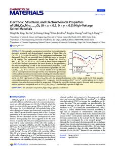
Figure 2. XRD patterns of (a) pure PVdF-HFP, (b) pure SN, (c) 20% PVdF-HFP + 80% SN, 20% PVdF-HFP + [(80 − x)% SN + x% BMPTFSI] for (d) x = 1, (e) x = 5, and (f) x = 10, and 20% PVdFHFP + [(80 − x)% SN + x% EMITf] for (g) x = 1, (h) x = 5, (i) and x = 10, recorded at room temperature (∼25 °C).
■
RESULTS AND DISCUSSION Structural Investigations: SEM, XRD, and Vibrational Spectroscopy. To study the morphological changes due to the addition of SN in PVdF-HFP and the addition of ILs BMPTFSI or EMITf in the SN/PVdF-HFP network, the comparative SEM images have been recorded, as shown in Figure 1. When 80 wt % SN is added to the host polymer PVdF-HFP, the composite system appears like a flat rock surface, indicating that SN fills the porous texture of the host polymer (Figure 1a and b). Upon the dispersion of ILs, the following specific changes have been noted in the morphological features: (a) Upon the addition of 1 wt % of IL BMPTFSI, the PVdFHFP/SN network shows the granular texture containing welldefined spherical entities (Figure 1c). Upon increasing the IL
added with different amounts of ILs (BMPTFSI and EMITf). The XRD pattern of the pure PVdF-HFP film shows the typical characteristics of a semicrystalline microstructure with predominant peaks at 2θ = 17.6, 19.7, 26.6, and 38.9° (Figure 2a). Pure SN shows the sharp characteristic peaks at 20 and 28° (Figure 2b). The following important points may be noted when SN and ILs are added to the host polymer PVdF-HFP: (a) Upon the addition of SN in 20 wt % PVdF-HFP, the sharp XRD peaks of SN retain the same 2θ values (Figure 2c), indicating almost the composite nature of the PVdF-HFP/SN system. 7438
dx.doi.org/10.1021/jp312358x | J. Phys. Chem. B 2013, 117, 7436−7443
The Journal of Physical Chemistry B
Article
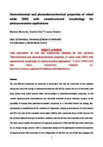
Figure 3. (A) Raman spectra of (a) pure PVdF-HFP, (b) pure SN, (c) 20% PVdF-HFP + 80% SN (w/w), (d) 20% PVdF-HFP + 75% SN + 5% BMPTFSI, (e) 20% PVdF-HFP + 75% SN + 5% EMITf in the 750−950 cm−1 spectral region, and (B) FTIR spectra for (a) pure PVdF-HFP, (b) pure SN, (c) 20% PVdF-HFP + 80% SN (w/w), (d) pure BMPTFSI, (e) 20% PVdF-HFP + 75% SN + 5% BMPTFSI, (f) pure EMITf, and (g) 20% PVdF-HFP + 75% SN + 5% EMITf.
CN triple bond of SN always has a tendency to interact with metal ions/cations.37 (ii) A relatively broader FTIR peak at 874 cm−1, associated with the amorphous phase of PVdF-HFP,14,38 gets substantially narrower due to the addition of SN or SN/ILs, as shown in Figure 3B. This indicates a substantial conformational change in the PVdF-HFP texture due to the addition of SN or SN/ILs. Further, this PVdF-HFP peak, which is relatively symmetrical, becomes more asymmetrical; rather, it can be split into two distinct peaks. This indicates that the nitrile group of SN has a tendency to interact with the PVdF-HFP backbone. Thermal Properties: TGA and DSC. Figure 4 shows the TGA curves of the pure PVdF-HFP film, the PVdF-HFP/SN composite, and the GPEs PVdF-HFP/SN/ILs. The host
(b) Upon the addition of ILs (BMPTFSI or EMITf), these sharp characteristic peaks of SN diminish. Instead, two broad peaks appear between 15 and 40°, centered at ∼20 and ∼26.5° (Figure 2d−i), which indicate the predominant amorphous nature of the PVdF-HFP/SN/ILs gel electrolyte materials. Further, the disappearance of sharp SN peaks upon the addition of ILs indicates the interaction of ILs with SN to form amorphous SN/ILs electrolytes, a part of the entire amorphous PVdF-HFP/SN/ILs GPEs. (c) Such a predominant amorphous nature of GPE at room temperature (even above −40 °C) is confirmed from DSC studies, discussed later. In order to investigate the possible interactions among PVdF-HFP, SN and ILs (BMPTFSI or EMITf) in the GPE systems, the FTIR and Raman spectroscopic analyses have been performed. Figure 3 represents the comparative Raman and FTIR spectra of the pure PVdF-HFP film, the pure SN, the PVdF-HFP/SN system, and the PVdF-HFP/SN/ILs gel electrolytes. The following distinctive features can be extracted from the spectral responses: (i) The Raman peak at 814 cm−1 (assigned to the νC−CN band of SN)36 is not much affected due to its addition to PVdFHFP (Figure 3A, b and c). This further indicates the composite nature of the PVdF-HFP/SN system as was indicated earlier in XRD studies. However, a weak interaction between SN and the PVdF-HFP polymeric backbone cannot be ruled out, as indicated by the FTIR study described below. A close inspection indicates that upon the addition of ILs, this SN peak becomes relatively asymmetric. In addition, a new peak at 838 cm−1 distinctly arises due to the addition of ILs (Figure 3A, d and e). A small peak at ∼838 cm−1 is also present in pure PVdF-HFP (Figure 3A, a), but after the addition of ∼80 wt % SN in PVdF-HFP, the peak gets suppressed. This is possible due to the dominance of SN over the PVdF-HFP. A small peak further arises upon the addition of ILs in the PVdF-HFP/SN system, as mentioned above. This is attributed to the interactions of IL component ions with SN molecules. The
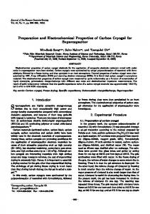
Figure 4. TGA curves of (a) pure PVdF-HFP, (b) 20% PVdF-HFP + 80% SN, (c,d) 20% PVdF-HFP + [(80 − x)% SN + x% BMPTFSI] for x = 5 and 20, and (e−g) 20% PVdF-HFP + [(80 − x)% SN + x% EMITf] for x = 5, 10, and 20, respectively. 7439
dx.doi.org/10.1021/jp312358x | J. Phys. Chem. B 2013, 117, 7436−7443
The Journal of Physical Chemistry B
Article
the melting peak of SN disappears when ILs of even 1 wt % are dispersed to the PVdF-HFP/SN system (Figure 5d−g). The gel electrolytes with higher IL contents also show a similar feature. However, no change has been observed in phase transition in SN at −40 °C for any gel composition (Figure 5). The absence of a melting peak of SN and the presence of a phase transition peak in GPEs indicate that the phase transition of SN occurs from the monoclinic ordered phase to the completely disordered (amorphous) phase when ILs are added to the PVdF-HFP/SN system, even for a small amount. Electrochemical Properties: Electrochemical Stability and Ionic Conductivity. The ESW is the working voltage range over which an electrolyte remains safe and stable. The ESW of the present GPEs was evaluated by cyclic voltammetry using symmetrical platinum electrodes. Figure 6 shows the
polymer PVdF-HFP is thermally stable as almost no weight loss occurs up to ∼400 °C (Figure 4a). A marginal weight loss (∼5 wt %) has been observed up to 100 °C for the PVdF-HFP/SN composite (Figure 4b), which is mainly due to moisture loss. The onset of steep weight loss is found at ∼100 °C for this composite, owing to the fast decomposition of SN. The weight loss due to moisture is slightly less, and the onset temperature for steep weight loss has been marginally increased to 120−125 °C when ILs of different amounts are added to the PVdF-HFP/ SN system to form GPEs. Further, a plateau region has been observed between ∼225 and ∼400 °C for each PVdF-HFP/ SN/BMPTFSI gel electrolyte system (Figure 4c and d). Such plateau regions are narrower for PVdF-HFP/SN/EMITf, which indicates the relatively lower thermal stability of the EMITfbased gel system over the BMPTFSI systems. The DSC curves of pure PVdF-HFP, pure SN, the PVdFHFP/SN composite, and different compositions of PVdFHFP/SN/ILs are presented in Figure 5. The following
Figure 6. CV responses of GPE films 20% PVdF-HFP + 75% SN + 5% ILs (a) BMPTFSI and (b) EMITf, recorded using symmetrical platinum electrodes at a scan rate of 1 mV s−1.
typical cyclic voltammograms of PVdF-HFP/SN/BMPTFSI and PVdF-HFP/SN/EMITf gel systems, recorded at the scan rate of 1 mV s−1. The voltage range of stability was chosen over which the voltammetric current was almost constant, and beyond this region, the onset of the increase in current was observed. The oxidation/reduction waves, observed in the voltammograms (which are within the tolerance limit), are due to the possible presence of adsorbed species like hydroxyl groups and/or due to the impurities. The ESW of BMPTFSIbased gel electrolytes has been observed from −3.2 to +3.2 V, which is found to be higher as compared to that for the EMITfbased electrolyte (i.e., from −2.6 to +2.6 V). The ILs, based on pyrrolidinium-based cationic structures, offer a substantially better reduction potential as compared to that of imidazoliumbased cations. This difference predominantly decides the ESWs of the ILs or IL-based systems. The commonly used anions such as Tf−, TFSI−, BF4−, and so forth show a very small variation in the oxidation potentials.39 The ESW values so obtained in the present work are suitable from a device application point of view particularly for high-performance supercapacitors. The variation of the room-temperature (25 °C) electrical conductivity (σ) of GPEs PVdF-HFP/SN/ILs as a function of content of ILs (BMPTFSI or EMITf) is shown in Figure 7. The room-temperature conductivity of pure SN has been reported to be ∼1 × 10⁻⁷ S cm−1, which is mainly due to the presence of impurities.29,30 The conductivity of the PVdF-HFP/SN composite is observed to be ∼2.2 × 10⁻⁷ S cm−1, which is possible also for the same reason that is due to the presence of impurities. An interesting feature may be noted upon the addition of ILs to the PVdF-HFP/SN system at room
Figure 5. DSC curves of (a) pure PVdF-HFP film, (b) pure SN, (c) 20% PVdF-HFP + 80% SN, (d−f) 20% PVdF-HFP + [(80 − x)% SN + x% BMPTFSI], and (g−i) 20% PVdF-HFP + [(80 − x)% SN + x% EMITf] for x = 1, 5, and 10, respectively.
important features can be extracted from the comparative DSC studies. An endothermic peak observed at ∼145 °C corresponds to the melting temperature of the PVdF-HFP host polymer film. The glass transition temperature (Tg) of the pure PVdF-HFP film is about −65 °C (Figure 5a). Pure SN shows two characteristics peaks at −40 and 56 °C (Figure 5b). The sharp peak at −40 °C corresponds to a transition from an ordered phase, classified as monoclinic, to an orientationally disordered phase, referred to as body-centered cubic (bcc) and also known as the plastic crystalline phase.31−33 Another sharp peak at ∼56 °C is attributed to the melting of SN.24−28 Upon the addition of 20 wt % PVdF-HFP in SN, the composite shows predominant characteristic DSC peaks of SN without any marked changes (Figure 5c). The melting peak of PVdF-HFP is not seen distinctly when added to SN because of its lower proportion and possible overlapping with decomposition of SN beyond 100−125 °C. A significant change may be noted that 7440
dx.doi.org/10.1021/jp312358x | J. Phys. Chem. B 2013, 117, 7436−7443
The Journal of Physical Chemistry B
Article
(v) The host polymer PVdF-HFP gives a dimensional stability to the gel system to provide a shape of free-standing thick films. It has been noticed that the variation in the electrical conductivity with respect to the content of ILs is masked due to the initial large-scale jump in the conductivity (Figure 7). In order to exhibit the effect of further addition of ILs (with a proportional decrease in the amount of SN), the conductivity value of PVdF-HFP/SN has been excluded; the σ versus IL content is redrawn and depicted in the inset of Figure 7. It may be noted that the conductivity variation with respect to the increase in IL content shows the two-maxima feature. The entire compositional range of the material may be divided into two regions, the region S1 (in which the SN content is dominant over the ILs) and the region S2 (in which IL content is dominant over the SN). In the SN-dominating region S1, the initial increase in the conductivity is associated with the increase in concentration of almost free ions in the high dielectric constant medium, as discussed above. A maximum is achieved at ∼5−10 wt % of ILs followed by a slight decrease in the conductivity. This decrease in conductivity is associated with the relative increment in the number of component ions, leading to the formation of ion pairs (MX: M and X being the cation and anion, respectively); as a result, the number of mobile charged species is reduced. Upon the continuous increase in IL amount, a further increase in the conductivity is observed in the S2 region, and another maximum is obtained for the IL content of ∼38−40 wt %. This increase in the conductivity is related to the large increase in the component ions, whose movements are supported by the rotational motion of the substantially available SN molecules. Further, there is always a possibility of the formation of some multiplets (e.g., M2X+, MX2−, and so forth), which contribute to the ionic conductivity enhancement. The decrease in ionic conductivity after attaining these second maxima upon further addition of ILs is due to the substantial decrement in the SN molecules, which were sufficiently available earlier for assisting the ionic mobility. Figure 8 shows the temperature dependence of the electrical conductivity of the PVdF-HFP/SN composite and PVdF-HFP/ SN/ILs GPEs. As shown in the Figure 8a, two steps in log σ versus 1/T plots are observed, one around −40 °C that
Figure 7. Variation of room-temperature ionic conductivity of PVdFHFP/SN/ILs GPE films as a function of IL content, that is (a) BMPTFSI and (b) EMITf. The expanded representation of the conductivity variation is shown as an inset.
temperature. Upon the addition of even 1 wt % of ILs (BMPTFSI or EMITf), the conductivity shoots up significantly by about 4 orders of magnitude, that is, from ∼2.2 × 10⁻⁷ to ∼2.6 × 10⁻³ S cm−1 for BMPTFSI and ∼7.5 × 10⁻³ S cm−1 for EMITf. Upon further addition of ILs up to 80 wt %, the GPEs offer almost the same order of ionic conductivity (Figure 7). If a small amount of IL (∼1−2 wt %) is added to the pure network of PVdF-HFP, the ionic conductivity would be very poor. The semicrystalline polymer like PVdF-HFP basically hinders the ionic mobility. The addition of a large amount of ILs only (∼70−80 wt %) leads to the high ionic conductivity of such binary systems. The textural changes of the PVdF-HFP/ SN network and phase change from the crystalline to amorphous nature of the host (discussed in XRD, DSC, and SEM studies), providing more free volume for easy ion transport, are also responsible to the enhancement in ionic conductivities. The textural change in the form of a porous structure enhances the ability of the PVdF-HFP/SN network to hold the larger content of ILs. In the present case, the sudden jump in the conductivity due to the addition of even 1−2 wt % of ILs is explained as follows: (i) In the present electrolyte system, the host network is PVdF-HFP/SN with the predominant amount of SN initially. (ii) Pure room-temperature ILs contain cations−anions, which are dissociated/separated in their own medium of dielectric constant 15−17;40 hence, they offer high ionic conductivity on the order of ∼10−3 S cm−1 at room temperature. (iii) When a small amount of IL is dispersed in the PVdFHFP/SN network, the ions of IL become further separated in the medium of higher dielectric constant (the dielectric constant of SN being 55)22 and become almost free for conduction. (iv) The rotational motion of SN molecules (in the plastic crystalline phase at room temperature) heavily supports the ionic mobility via a paddle-wheel mechanism.41 Thus, the substantial enhancement in the electrical conductivity from ∼10−7 S cm−1 (for PVdF-HFP/SN network containing no ions) to the ionic conductivity of ∼10−3 S cm−1 of the PVdFHFP/SN/IL gel electrolyte system has become possible.
Figure 8. Temperature dependence of ionic conductivity of (a) the 20% PVdF-HFP + 80% SN (w/w) sytem, (b) 20% PVdF-HFP + 75% SN + 5% BMPTFSI, and (c) 20% PVdF-HFP + 75% SN + 5% EMITf GPEs. 7441
dx.doi.org/10.1021/jp312358x | J. Phys. Chem. B 2013, 117, 7436−7443
The Journal of Physical Chemistry B
Article
• The ESWs of the two types of GPE films with ILs BMPTFSI and EMITf are from −3.2 to +3.2 and from −2.6 to +2.6 V, respectively. • The temperature dependence of the ionic conductivity shows an Arrhenius-type thermally activated process and has been correlated with the different transitions observed from DSC results. The gel materials can be used as electrolytes in ionic devices for the temperature range from −40 to ∼100 °C. The present PVdF-HFP/SN/ILs gel polymer films appear to be excellent electrolyte materials in energy storage ionic devices, particularly in electrical double-layer capacitors (EDLCs)/supercapacitors.
corresponds to a normal to plastic crystalline phase transition and the other at ∼60 °C that corresponds to the melting of SN in the PVdF-HFP/SN composite system. These transitional steps correspond to the transition peaks in DSC scans, described in the previous section.23,24,29,30 The step changes in the conductivity at around −40 °C have been observed for the GPEs also containing both ILs, BMPTFSI and EMITf (Figure 8b and c). This is due to the normal monoclinic ordered phase to completely disordered phase transition, which has its signature in the DSC scans as well. Furthermore, the ionic conductivity is very low (∼10−7 S cm−1) below −40 °C. This lower conductivity is due to the gauche conformation of SN, existing below −40 °C, in which all rotational motions are almost seized. It may be specifically noted that the other transition, occurring at ∼56 °C (due to melting of SN), does not appear in σ versus 1/T plots for the PVdF-HFP/SN/ILs GPEs (Figure 8b and c). The disappearance of melting peaks of PVdF-HFP/SN/ILs GPEs has been observed in DSC scans also (Figure 8d−g). The log σ versus 1/T plots are linear for each material, which indicates the Arrhenius-type thermally activated behavior below and after each transition (Figure 8). Accordingly, the ionic conductivity relation with temperature can be expressed as ⎛ −E ⎞ σ = σ0 exp⎜ a ⎟ ⎝ kT ⎠
■
*E-mail:
[email protected]. Tel.: +91 1127604881. Fax: +91 1127667061. Notes
The authors declare no competing financial interest.
■
ACKNOWLEDGMENTS The authors acknowledge the financial support received from the Department of Science & Technology, New Delhi (Sanction No. DST/TSG/PT/2009/93) and the University of Delhi (under the scheme to strengthen R&D doctoral research programme providing funds to University faculty, 1117 Research Fund).
(1)
■
where σ0 is the pre-exponential factor, Ea is the activation energy, and k is the Boltzmann constant. The activation energy values are marked on the σ versus 1/T plots for different temperature ranges (Figure 8).
■
AUTHOR INFORMATION
Corresponding Author
REFERENCES
(1) Chandra, S.; Laskar, A. Superionic Solids and Solid Electrolytes; Academic: San Diego, CA, 1989. (2) Bruce, P. G. Solid State Electrochemistry; Cambridge: Great Britain, 1995. (3) Quartarone, E.; Mustarelli, P. Electrolytes for Solid-State Lithium Rechargeable Batteries: Recent Advances and Perspectives. Chem. Soc. Rev. 2011, 40, 2525−2540. (4) MacCallum, J. R., Vincent, C. A., Eds. Polymer Electrolyte Reviews; Elsevier Applied Sciences Publisher: London, 1987 and 1989, Vol. 1 and 2. (5) Scrosati, B. Ed. Applications of Electroactive Polymers; Chapman and Hall: London, 1993. (6) Gray, F. M. Solid Polymer Electrolytes: Fundamental and Technological Applications; VCH: New York, 1991. (7) Gray, F. M. Polymer Electrolytes; Royal Society of Chemistry Monographs: Cambridge, U.K., 1997. (8) Agrawal, R. C.; Pandey, G. P. Solid Polymer Electrolytes: Materials Designing and All-Solid-State Battery Applications: An Overview. J. Phys. D: Appl Phys. 2008, 41, 223001. (9) Manuel Stephan, A. Review on Gel Polymer Electrolytes for Lithium Batteries. Eur. Polym. J. 2006, 42, 21−42. (10) Tominaga, Y.; Asai, S.; Sumita, M.; Panero, S.; Scrosati, B. Fast Ionic Conduction in PEO-Based Composite Electrolyte Filled with Ionic Liquid-Modified Mesoporous Silica. Electrochem. Solid State Lett. 2005, 8, A22−A25. (11) Tominaga, Y.; Asai, S.; Sumita, M.; Panero, S.; Scrosati, B. A Novel Composite Polymer Electrolyte: Effect of Mesoporous SiO2 on Ionic Conduction in Poly(ethylene oxide)−LiCF3SO3 Complex. J. Power Sources 2005, 146, 402−406. (12) Shin, J.-H.; Henderson, W. A.; Passerini, S. PEO-Based Polymer Electrolytes with Ionic Liquids and Their Use in Lithium Metal− Polymer Electrolyte Batteries. J. Electrochem. Soc. 2005, 152, A978− A983. (13) Kim, G.-T.; Appetecchi, G. B.; Alessandrini, F.; Passerini, S. Solvent-Free, PYR1ATFSI Ionic Liquid-Based Ternary Polymer Electrolyte Systems I. Electrochemical Characterization. J. Power Sources 2007, 171, 861−869.
CONCLUSIONS
Novel compositions of GPEs consisting of IL (BMPTFSI or EMITf) solutions in a plastic crystalline SN, immobilized in a host polymer PVdF-HFP, have been prepared and characterized. On the basis of various morphological, structural, thermal, and electrochemical studies, the following conclusions have been drawn: • The gel electrolyte films are free-standing and flexible with excellent mechanical/dimensional integrity. • Addition of even a small amount of ILs and a subsequent increase in their content lead to drastic morphological/ structural changes in the PVdF-HFP/SN system, particularly from crystalline to amorphous character and porosity, as evidenced from the SEM, XRD, and DSC studies. • The thermal stability of the PVdF-HFP/SN system is marginally improved from 100 to 120 °C upon introducing the ILs. The BMPTFSI-based gel electrolyte offers better thermal stability over the EMITf-based gel system. • FTIR and Raman spectroscopic studies indicate interactions of the nitrile group of SN with ILs and the PVdF-HFP backbone in the GPEs. • Upon the incorporation of only 1 wt % of ILs in the PVdFHFP/SN system, the electrical conductivity of the GPEs increases substantially by 4 orders of magnitude (i.e., from ∼10−7 to ∼10−3 S cm−1) at room temperature. The EMItriflate-based electrolyte shows slightly higher conductivity as compared to the BMPTFSI-based electrolyte. The variations in conductivity with respect to the compositions of electrolytes show a two-maxima feature. 7442
dx.doi.org/10.1021/jp312358x | J. Phys. Chem. B 2013, 117, 7436−7443
The Journal of Physical Chemistry B
Article
(14) Pandey, G. P.; Hashmi, S. A. Experimental Investigations of an Ionic-Liquid-Based, Magnesium Ion Conducting, Polymer Gel Electrolyte. J. Power Sources 2009, 187, 627−634. (15) Rao, M.; Geng, X.; Liao, Y.; Hu, S.; Li, W. Preparation and Performance of Gel Polymer Electrolyte Based on Electrospun Polymer Membrane and Ionic Liquid for Lithium Ion Battery. J. Membr. Sci. 2012, 399−400, 37−42. (16) Armand, M.; Endres, F.; MacFarlane, D. R.; Ohno, H.; Scrosati, B. Ionic-Liquid Materials for the Electrochemical Challenges of the Future. Nat. Mater. 2009, 8, 621−629. (17) Hapiot, P.; Lagrost, C. Electrochemical Reactivity in RoomTemperature Ionic Liquids. Chem. Rev. 2008, 108, 2238−2264. (18) MacFarlane, D. R.; Forsyth, M.; Howlett, P. C.; Pringle, J. M.; Sun, J.; Annat, G.; Neil, W.; Izgorodina, E. I. Ionic Liquids in Electrochemical Devices and Processes: Managing Interfacial Electrochemistry. Acc. Chem. Res. 2007, 40, 1165−1173. (19) Wei, D.; Ng, T. W. Application of Novel Room Temperature Ionic Liquids in Flexible Supercapacitors. Electrochem. Commun. 2009, 11, 1996−1999. (20) Kim, G. T.; Appetecchi, G. B.; Carewska, M.; Joost, M.; Balducci, A.; Winter, M.; Passerini, S. UV Cross-Linked, LithiumConducting Ternary Polymer Electrolytes Containing Ionic Liquids. J. Power Sources 2010, 195, 6130−6137. (21) Kunze, M.; Jeong, S.; Appetecchi, G. B.; Schönhoff, M.; Winter, M.; Passerini, S. Mixtures of Ionic Liquids for Low Temperature Electrolytes. Electrochim. Acta 2012, 8 (2), 69−74. (22) Alarco, P. J.; Abu-Lebdeh, Y.; Abouimrane, A.; Armand, M. The Plastic-Crystalline Phase of Succinonitrile as a Universal Matrix for Solid-State Ionic Conductors. Nat. Mater. 2004, 3, 476−481. (23) Fan, L.-Z.; Wang, X.-L.; Long, F. All-Solid-State Polymer Electrolyte with Plastic Crystal Materials for Rechargeable Lithium-Ion Battery. J. Power Sources 2009, 189, 775−778. (24) Fan, L.-Z.; Maier, J. Composite Effects in Poly(ethylene oxide)− Succinonitrile Based All-Solid Electrolytes. Electrochem. Commun. 2006, 8, 1753−1756. (25) Das, S.; Prathapa, S. J.; Menezes, P. V.; Guru Row, T. N.; Bhattacharyya, A. J. Study of Ion Transport in Lithium PerchlorateSuccinonitrile Plastic Crystalline Electrolyte via Ionic Conductivity and In Situ Cryo-Crystallography. J. Phys. Chem B 2009, 113, 5025−5031. (26) Patel, M.; Menezes, P. V.; Bhattacharyya, A. J. Ion Transport in a Polymer−Plastic Solid Soft Matter Electrolyte in the Light of Solvent Dynamics and Ion Association. J. Phys. Chem B 2010, 114, 5233−5240. (27) Fan, L.-Z.; Hu, Y.-S.; Bhattacharyya, A. J.; Maier, J. Succinonitrile as a Versatile Additive for Polymer Electrolytes. Adv. Funct. Mater. 2007, 17, 2800−2807. (28) Huang, J.; Hill, A.; Forsyth, M.; MacFarlane, D.; Hollenkamp, A. Conduction in Ionic Organic Plastic Crystals: The Role of Defects. Solid State Ionics 2006, 177, 2569−2573. (29) Long, S.; MacFarlane, D. R.; Forsyth, M. Ionic Conduction in Doped Succinonitrile. Solid State Ionics 2004, 175, 733−738. (30) Van Eijck, L.; Best, A. S.; Long, S.; Fernandez-Alonso, F.; MacFarlane, D.; Forsyth, M.; Kearley, G. J. Localized Relaxational Dynamics of Succinonitrile. J. Phys. Chem. C 2009, 113, 15007−15013. (31) Timmermans, J. Plastic Crystals: A Historical Review. J. Phys. Chem. Solids 1961, 18, 1−8. (32) Derollez, P.; Lefebvre, J.; Descamps, M.; Press, W.; Fontaine, H. Structure of Succinonitrile in Its Plastic Phase. J. Phys.: Condens. Matter 1990, 2, 6893−6903. (33) Fengler, O. I.; Ruoff, A. Vibrational Spectra of Succinonitrile and its [1,4-13C2]-, [2,2,3,3-2H4]- and [1,4-13C2-2,2,3,3-2H4]-Isotopomers and a Force Field of Succinonitrile. Spectrochim. Acta, Part A 2001, 57, 105−117. (34) Abu-Lebdeh, Y.; Alarco, P. J.; Armand, M. Single-Phased Organic Plastic Crystal Electrolytes. J. New. Mater. Electrochem. Systems 2004, 7, 29−31. (35) Forsyth, M.; Pringle, J. M.; MacFarlane, D. R. Ion Conduction in Plastic Crystals. In Electrochemical Aspects of Ionic Liquids; Ohno, H., Ed.; Wiley: Hoboken, NJ, 2005; pp 289−304.
(36) Aravindan, V.; Vickraman, P. Nanoparticulate AlO(OH)n Filled Polyvinylidenefluoride-co-hexafluoropropylene Based Microporous Membranes for Lithium Ion Batteries. J. Renewable Sustainable Energy 2009, 1, 023108/1−023108/11. (37) Farona, M. F.; Bremer, N. J. Succinonitrile Derivatives of Halogenopentacarbonyl-Manganese (I). J. Am. Chem. Soc. 1966, 88, 3735−3737. (38) Sim, L. N.; Majid, S. R.; Arof, A. K. FTIR Studies of PEMA/ PVdF-HFP Blend Polymer Electrolyte System Incorporated with LiCF3SO3 Salt. Vibr. Spectrosc. 2012, 58, 57−66. (39) Buzzeo, M. C.; Evans, R. G.; Compton, R. G. NonHaloaluminate Room-Temperature Ionic Liquids in Electrochemistry−A Review. Chem. Phys. Chem. 2004, 5, 1106−1120. (40) Zhang, S.; Sun, N.; He, X.; Lu, X.; Zhang, X. Physical Properties of Ionic Liquids: Database and Evaluation. J. Phys. Chem. 2006, 35, 1475−1517. (41) MacFarlane, D. R.; Forsyth, M. Plastic Crystal Electrolyte Materials: New Perspectives on Solid State Ionics. Adv. Mater. 2001, 13, 957−966.
7443
dx.doi.org/10.1021/jp312358x | J. Phys. Chem. B 2013, 117, 7436−7443