PROCEEDINGS OF THE INTERNATIONAL CONFERENCE NANOMATERIALS: APPLICATIONS AND PROPERTIES Vol. 3 No 1, 01PCSI05(4pp) (2014)
Structural Properties of Magnesium Oxide Thin Films Deposited by Spray Pyrolysis Technique A.V. Dyachenko1,*, A.S. Opanasuyk1, D.I. Kurbatov1, S.B. Bolshanina1, V.M. Kuznetsov2 2
1 Sumy State University, 2, Rymsky Korsakov Str., 40007 Sumy, Ukraine Institute of Applied Physics NAS of Ukraine, 58, Petropavliska Str., 40030 Sumy, Ukraine
(Received 23 July 2014; published online 29 August 2014) In this work, structural properties of magnesium oxide films have studied by X-ray diffraction methods. MgO obtained by spray pyrolysis technique at the different substrate temperatures on the glass substrates. The 0.2 M magnesium chloride hexahydrate aqueous solution was selected as a precursor in the solution. The influence of substrate temperature on the phase composition, texture quality, coherent scattering domain size and lattice constant of the material was investigated. The research results can be used in the development of functional layers of solar cells thin film. Keywords: X-ray, Structural properties, Spray pyrolysis technique, MgO, Thin films, Solar cells. PACS numbers: 81.05.Dz, 81.15.Rs
1. INTRODUCTION
2. EXPERIMENTAL DETAILS
Nowadays, oxide materials are widely used in the producing of integrated circuits, opto-, acousto- and microelectronics, solar energy and other areas of modern industry [1]. Magnesium oxide is one of the most wide band gap compounds of A2B6 group (Eg = 7,3 eV). It has a high melting temperature of 2800 0C, large yield of secondary electrons during the bombardment by ions [2]. Furthermore it is stable at atmospheric. This led to the prospect of its use as an insulating coating of electrodes in magneto hydrodynamic devices, Josephson junctions and catalysis, insulating layer in magnetic tunnel junctions, in plasma technology devices [3-10]. MgO thin films can also be used as anti-refrective layers of solar cells based on different absorbing materials. There are several methods of the preparation of MgO films and coatings, such as pulsed laser deposition, magnetron sputtering, electron beam evaporation, metal organic chemical vapor deposition, spray pyrolysis, etc. [11-14]. Recently, much attention has been attracted to chemical methods of obtaining of metal oxides films, one of which is a spray pyrolysis technique. This method is one of the most prospective for the deposition of semiconductors thin films due to its simplicity and low cost, high speed of deposition layer and the possibility of obtaining condensates on large area substrates of different materials, because this technology is a non-vacuum. There are several groups of researchers from different countries involved to study of MgO films [1521], but the structural and substructural properties of MgO films, obtained by spray pyrolysis method and their dependence on physical-technological conditions of the deposition have, been insufficiently studied. Therefore, in this paper we investigate the impact on the structural properties of magnesium oxide films deposited from a magnesium chloride solution with different temperature with the same other conditions.
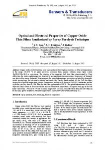
Investigated magnesium oxide films were obtained on glass substrates 2x2 cm2. Before deposition the substrates surface were cleaned in the tub with ethanol for 5 minutes. The 0.2 M magnesium chloride hexahydrate aqueous solution was selected as a precursor solution. It should be noted that in the most studies as a precursor of the deposition of MgO films, there was used solution based on magnesium acetate or magnesium acetylacetonate [15-16, 18, 20-21]. The temperature of the synthesis of compounds was selected by the results of analysis of published data. In article [16] getting of magnesium oxide films was conducted at the substrate temperature from 380 0C up to 600 0C. The authors of [21] performed dispersion of precursor based on Mg(CH3COO)24H2O at substrate temperatures of Ts = 400 - 600 0C. In work [15] the substrate temperature for deposition of MgO films with an aqueous solution of 0.5 M magnesium acetate Mg(CH3COO)24H2O varied from Ts = 580 0C to 680 0C. In present work the films were deposited at the substrate temperature varied in the range from Ts = 300 0C to 500 0C with step 50 0C, and from Ts = 370 0C to 420 0C with a smaller step 10 0C. The laboratory system, the schematic diagram of which is shown in Fig. 1, was used for spray the solution of precursors for the synthesis of magnesium oxide thin films. The laboratory system consists of a heater, with the help of which the steel plate with fixed substrate is heated; a thermocouple for registering the values of the substrate temperature, a spray gun with diameter of nozzle 0.2 mm, comprising: a reservoir for the starting precursor and a atomization nozzle. The compressor, that provides air flow to transport dispersed precursor particles from the nozzle to the heated substrate, is connected to this gun. Substrates temperature during the obtaining of films was measured using а chromel-alumel thermocouple. The distance between the nozzle and the heated substrate surface was equal to 12 cm. To transport dis-
*
[email protected]
2304-1862/2014/3(1)01PCSI05(4)
01PCSI05-1
2014 Sumy State University
A.V. DYACHENKO , A.S. OPANASUYK, D.I. KURBATOV, KUZNETSOV V.M. persed precursor particles, the air flow with a pressure of 0.2 MPa was used. Spraying rate was 2 ml/min at volume of sprayed solution of 3 ml per sample.
PROC. NAP 3, 01PCSI05 (2014) a
2sin
(h2 k2 l2 ) .
The lattice constants were determined using Nelson-Riley extrapolation method [25]. The linear approximation of obtained points was conducted using the method of least squares with the help of OriginPro software package. The average size of coherent scattering domains (CSD) L was determined by Scherer’s formula [24]: L
Fig. 1 – Schematic diagram of experimental laboratory system for obtaining MgO thin films by spray-pyrolysis technique.
The laboratory system that was used for spray the solution of precursors for the synthesis of magnesium oxide thin films is more detailed described in work [22]. X-ray diffractometer DRON 4-07 in Ni-filtered Kα radiation of copper anode (U = 30 kV, I = 20 mA) was used to determine the structural properties. The measurement was conducted in a range of 2θ angles from 20° to 80°, where 2θ is Bragg’s angle. The BraggBrentano focusing was used for research of x-ray radiation. The curves were normalized to the peak intensity of the (200) cubic phase of the compound. Phase analysis was performed by comparing interplane distances and relative intensities of the researched samples and the standard according to JCPDS The texture quality of the films has been estimated by Harris method. Pole density was calculated by the following formula:
Pi
I i 1 N
I 0i
N
I i 1
i
I 0i
0,94 b cos
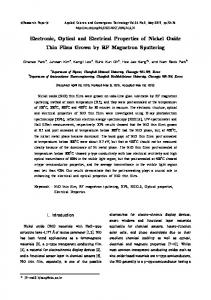
where k — coefficient that depends on the shape of the particle (k = 1); λ — wavelength of X-rays; β — broadening of the corresponding X-ray lines; θ — diffraction angles of the analyzed lines. 3. RESULT AND DISCUSSION Visual inspection showed that the resulting films were optically transparent and uniform. Fig. 2 shows the diffraction patterns of MgO films deposited at substrate temperatures range: from 300 0С to 500 0С. Their analysis shows that at Ts = 300 0C films with the phase composition corresponding to the compound Mg2(OH)3Cl4H2O were grown. At other temperatures in the diffraction patterns there were found additional peaks at angles close to 12,300; 24,700 and 31,600 that can be attributed to a hydroxyl compounds of magnesium. This testifies to the incomplete transformation of precursors in necessary phase and necessity of post-annealing of patterns. Thus, layers obtained at the substrate temperature range Ts = 380420 0C really have contained MgO with cubic modification and with the preferred axial texture [111]. It has allowed to define temperature regimes for the obtain magnesium oxide films with nanocrystalline structure and to explore the films in more detail.
where Ii, I0i — integrated intensities of the i-th diffraction peak for the film sample and standard; N — the number of lines that are present on the diffraction pattern. After then Pi – (hkl)i and Pi – φ dependences, where φ is the angle between the axis of the texture and perpendicular to different crystallographic planes, which correspond to reflections on the diffractograms, (hkl) — Miller indexes were made. This angle was calculated for the cubic lattice, using the expressions given in [26]. Texture axis has those indexes, which correspond to the largest value of Pi. The orientation factor of the sample can be calculated from the expression:
f
Fig. 2 – XRD patterns of MgO films obtained at different substrate temperatures Ts, 0C: 300 (1), 350 (2), 380 (3), 400 (4), 420 (5), 450 (6), 480 (7), 500 (8).
1 N 2 Pi 1 . N i 1
Calculation of the constants a and c of the hexagonal phase of the material was held by the formula:
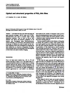
Fig. 3 shows the diffraction patterns of MgO films deposited at substrate temperatures range from 370 0С to 420 0С. In the diffractograms the lines at the angles of
01PCSI05-2
STRUCTURAL PROPERTIES OF MAGNESIUM OXIDE THIN FILMS… 2θ=36.800, 42.840, 62.160, 78.440, which corresponded to the reflection from the planes of (111), (200), (220), (222)
PROC. NAP 3, 01PCSI05 (2014) As can be seen from the figure, with increasing the substrate temperature, the corresponding value of orientation factor also increases. This suggests that with increasing the substrate temperature the quality of obtained films’ textures increases. The dependence of the lattice constant of MgO on the substrate temperature during film deposition is presented in Fig. 5. The dotted line in the figure shows the values given for this connection in the directory [23]. The method, that was used, allows to find the lattice constant of materials with an accuracy of 0.001%.
Fig. 3 – XRD patterns of MgO films obtained at different substrate temperatures Ts, 0C: 370 (1), 380 (2), 390 (3), 400 (4), 410 (5) та 420 (6).
of the MgO cubic phase respectively [23]. Phase analysis of samples was carried out using handbook (JCPDS card № , 01-075-0477). In the diffraction patterns didn't lines of other phases observed, which testifies to the single phase character of samples, obtained in this temperatures range. X-ray analysis showed that the dominant intensity has reflections from crystallographic planes of (111) and (200) of cubic phase of magnesium oxide, which indicates the presence growth texture [111] in films. Similar growth texture was also observed by other researchers in the works [17-19]. Calculations of pole density Pi and orientation factor f made it possible to determine the axial texture of growth in MgO layers [111] Appropriate dependences of film’s orientation factor on the substrate temperature at which they were obtained are presented in Fig. 4 (inset).
Fig. 4 – Pole density (Pi ) as a dependent function of the angle φ between the axis of the texture and normal to the reflecting plane at temperatures and orientation factor (f) for films obtained at different substrate temperatures (inset).
Fig. 5 – Dependence of lattice constants in MgO films on the substrate temperature.
As can be seen from the figure, the lattice constant of MgO layer that was obtained at Ts = 370 0C, equal to a = 0.42154 nm. These values are lower than reference ones [23]. After increasing substrate temperature to Ts = 390 0C we observed a gradual increase in the lattice constant of the material (a = 0.42270 nm). With the further increase Ts there took place decrease of lattice parameters of the material. But all of the obtained values well correlate with the values given in the reference (a = 0.42200 nm) [23, 01-075-0447]. The results of calculating of the size of coherent scattering domains in MgO films in directions perpendicular to crystallographic planes of (111), (200), (220) and (222) are shown in Fig. 6.
Fig. 6 – Dependence of CSD sizes in MgO films on the substrate temperature. Values for crystal planes 1 - (220), 2 (200), 3 - (222) and 4 - (111) are presented.
01PCSI05-3
A.V. DYACHENKO , A.S. OPANASUYK, D.I. KURBATOV, KUZNETSOV V.M. It was established that the CSD sizes take the following values in the respective planes: L(111) = 13-26 nm, L(200) = 11-16 nm, L(220) = 10-14 nm, L(222) = 10-16 nm. As can be seen from the figure, there is a tendency to decreasing of CSD in their respective areas with increase of the substrate temperature. This indicates the deterioration of the crystalline quality of the films. This trend was especially noticeable for directions of [111] (curve 4 figure 6). It should be noted that the authors of [18] using the Sherrer’s ratio were obtained similar values of CSD sizes (L = 15 nm) for magnesium oxide films obtained from solutions magnesium acetylacetonate as precursor. Also, similar results L = 16 nm were obtained in [21]. These authors have synthesized films using hydrated magnesium acetate [Mg (CH3COO)24H2O] as precursor in ethanol with tri-ethylene glycol (TEG). 4. CONCLUSIONS In the work we have investigated structural (texture quality, the lattice constant) and some substructural (CSD sizes) characteristics of nanocrystalline magnesium oxide films which were obtained from the magnesium chloride hexahydrate aqueous solution by spray pyrolysis technique at the different substrate temperatures.
PROC. NAP 3, 01PCSI05 (2014)
It is established, that the obtained films of MgO were optically transparent and uniform. X-ray diffractometric researches have allowed to establish, that MgO film obtained at the substrate temperature Ts = 370-420 0C were single-phase and had cubic structure with a high-quoality texture growth of [111], the quality of which depended on Ts. The calculated values of lattice constant a = 0.4215-0.4227 nm, mostly correlate to reference ones. It was found the trend to a slight increase of a at the temperature of Ts = 370-390 0C, with following decreasing of lattice constant at high temperatures. It was established that the CSD sizes in MgO films in directions perpendicular to the crystallographic planes of (111), (200), (220) and (222) were L (111) = 13-26 nm, L (200) = 11-16 nm, L (220) = 10-14 nm, L (222) = 10-16 nm. Thus there was a tendency to decrease the size of L with increasing temperature of synthesis of thin layers. AKNOWLEDGEMENTS This research was supported by the Ministry of Education and Science of Ukraine (Grant No. 0113U000131 and 0112U000772).
REFERENCES 1. S. Kasap, P. Capper, The Springer Handbook of Electronic and Photonic Materials (Berlin: Springer: 2007). 2. W.B. Wang, Y. Yang, A. Yanguas-Gil, N.N. Chang, G.S. Girolami, and J.R. Abelson, Appl. Phys. Lett. 102, 101605 (2013). 3. S. Ikeda, K. Miura, H. Yamamoto, K. Mizunuma, H.D. Gan, M. Endo, S. Kanai, J. Hayakawa, F. Matsukura, H. Ohno, Nat. Mater. 9, 721 (2010). 4. S.S.P. Parkin, C. Kaiser, A. Panchula, P.M. Rice, B. Hughes, M. Smant, S.H. Yang, Nat. Mater. 3, 862 (2004). 5. P. Vuoristo, T. Mantyla, P. Kettunen, J. Vac. Sci. Technol. 4, 2932 (1986). 6. M.V. Costache, J.S. Moodera, Appl. Phys. Lett. 96, 082508 (2010). 7. H. Yamamori, A. Shoji, Supercond. Sci. Technol. 12, 877 (1999). 8. K. Sugiyama, K. Akazawa, M. Oshima, H. Miura, T. Matsuda, O. Nomura, Plasma Chem. Plasma Process. 6, 179 (1986). 9. R.H. Nibbelke, J. Scheerová, M.H.J.M de Croon, G.B. Maroon, J. Catal. 156, 106 (1995). 10. S. K. Mahadeva, J. Fan, A. Biswas, K. S. Sreelatha, L. Belova, K. V. Rao., Nanomaterials 3, 486 (2013). 11. J. Senzaki, K. Kurihara et al., J. Appl. Phys. 37, 5150 (1998). 12. M. Nashimoto K. Nashimoto, J. Appl. Phys. 33, L793 (1994). 13. D.K. Fork, F.A. Ponce et al., Appl. Phys. Lett. 58, 2294 (1991).
14. S. K. Ram, U. K. Barik, S. Sarkar, P. Biswas, V. Singh, H. K. Dwivedi, S. Kumar, Thin Solid Films 517, 6252 (2009). 15. Ji Ming Bian, Xiao Min Li, Tong Lai Chen, Xiang Dong Gao, Wei Dong Yu., Appl. Surf. Sci. 228, 297 (2004). 16. Xiaorong Fu, Guangming Wu, Shigeng Song, Zhitang Song, Xinzhong Duo., Appl. Surf. Sci. 148, 223 (1999). 17. Soo Gil Kim, Jin Yong Kim, Hyeong Joon Kim, Thin Solid Films 376, 110 (2000). 18. Xie Yi, Wang Wenzhong, Qian Yitai, Yang Li, Chen Zhiwen., Surf. Coat. Technol. 82, 291 (1996). 19. W.J. De Sisto, R.L. Henry, J. Cryst. Growth 109, 314 (1991). 20. O. Stryckmans, T. Segato, P.H. Duvigneaud, Thin Solid Films 283, 17 (1996). 21. A. Moses Ezhil Raj, L. C. Nehru, M. Jayachandran, and C. Sanjeeviraja., Cryst. Res. Technol. 42 (9), 867 (2007). 22. O.A. Dobrozhan, A.S. Opanasyuk, S.B. Bolshanіna, Odessa polytechnic university proceedings 3 (42), 173 (2013). 23. Selected powder diffraction data for education straining. Search manual and data cards (USA: International Centre for diffraction data: 1997) 24. X-ray Diffraction (Ed. B.E. Warren) (New York: Dover: 1990). 25. T.O. Berestok, D.I. Kurbatov, N.M. Opanasyuk, A.D. Pogrebnjak, A.D. Manzhos, S.M. Danilchenko, J. NanoElectron. Phys. 5 (1), 01001 (2013). 26. Ja. S. Umanskij, Crystallogaphy, X-ray graph and electronmicroscopy (Moskow: Metallurgy: 1982).
01PCSI05-4