Structure evolution of spider silk liquid crystalline precursor material. G. De Luca & A. D. Rey. Department of Chemical Engineering,. McGill University, Canada.
Management of Natural Resources, Sustainable Development and Ecological Hazards 381
Structure evolution of spider silk liquid crystalline precursor material G. De Luca & A. D. Rey Department of Chemical Engineering, McGill University, Canada
Abstract Spiders produce silk fibers with remarkable mechanical properties using an ultraoptimized spinning process. The fluid precursor material used to draw the silk threads is a lyotropic nematic liquid crystal. The mechanical properties of the silk fibers as well as their processability are strongly affected by the complex structural transitions undergone by the nematic liquid crystal precursor along the spinning line. Our work focuses on the particular structure adopted by the nematic precursor in the extrusion duct of the spinning apparatus. This structure is characterized by a succession of well defined point defects located on the axis of the cavity and interacting on each other through elastic mediated forces. The phenomenon described is both important in understanding the process-induced structuring of spider silk fibers and to defect physics. Keywords: Spider’s silk, liquid crystalline spinning, nematic point defects.
1 Introduction Spiders’ ultra-optimized and ecological spinning process produces a fiber with mechanical properties comparable or even superior to the best man-made superfibers, which use corrosive solvents and cause significant environmental degradation [1, 2]. Hence, there is a great deal of interest in understanding the intricacy of their design and processing routes. Many environment friendly exciting applications are envisaged upon the successful replication of spiders’ fibers and complex spinning line [3–5]. Spider silk fibers are known to be spun from a lyotropic nematic liquid crystal emerging from a highly concentrated water-based solution of rod-like molecules or aggregates [6–8]. A quintessential property of this silk precursor is its capacity WIT Transactions on Ecology and the Environment, Vol 99, © 2006 WIT Press www.witpress.com, ISSN 1743-3541 (on-line) doi:10.2495/RAV060381
382 Management of Natural Resources, Sustainable Development and Ecological Hazards
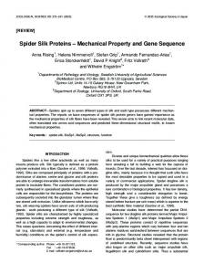
Figure 1: Structure of the radial (a) and hyperbolic (b) point defects found along the spinning duct of spiders in terms of the director field n(r).
to maintain some degrees of orientational order while still flowing as a liquid. This orientational order is characterized by the tendency that have neighboring rod-like units to align their long axis in parallel along a common direction [9, 10]. This preferred molecular orientation usually varies from subregion to subregion in the mesophase (i.e., intermediate phase) due to elastic effects coupled with geometrical and interfacial constraints [9]. The evolution of orientational order or molecular orientation along the spinning pathway is crucial as it affects the processability of the silk precursor mesophase and determines the microstructural details of the solidified fiber and therefore its remarkable physical properties [6–8]. Spiders’ spinning line basically consist in a tail where the silk precursor material is synthesized, a central bag where it is stocked in a very concentrated solution, and an extrusion duct from which the silk fiber is drawn [8, 11]. Observations made by polarized light microscopy in the extrusion duct have revealed the presence of a complex orientation structure known as escaped radial with point defects (ERPD) [8, 12–14]. The point defects, referred as hedgehogs or monopole, are located where the direction of bending distortions changes. At those particular locations, orientational order melts. Two types of point defects are alternatively found in the cylindrical cavity of the extrusion duct: the radial and the hyperbolic hedgehogs. Figure 1 shows the characteristic structures of the radial and hyperbolic hedgehogs in term of a director field n(r) giving the local average preferred orientation of the molecules. The unit directors are drawn arrowhead-free as there is no physical difference between the vector field n(r) and −n(r) [9, 10]. Whether this complex molecular structure is an accident of Nature or a necessary ingredient of the spider biospinning process is unknown at present. Nonetheless, one my hypothesized that this configuration with its orientational defects may play an important role in the control of material crystallization along with water pumping, ions exchanges and pH reduction phenomena [8]. Indeed, a premature WIT Transactions on Ecology and the Environment, Vol 99, © 2006 WIT Press www.witpress.com, ISSN 1743-3541 (on-line)
Management of Natural Resources, Sustainable Development and Ecological Hazards 383
crystallization of the silk may indeed cause the permanent blockage of the extrusion system and ultimately lead to the death of the animal [8, 15]. Nematic point defects confined in cylindrical geometries have been first experimentally observed and explained in the early seventies [16–19]. They are typically observed when a nematic mesophase is confined in cylindrical capillary with lateral walls enforcing strong radial anchoring (i.e. molecules are forced to orient radially at the surface). Point defects with opposite topological charges are known to annihilate by pairs. This has been experimentally observed [16–21] and theoretically described [20, 22–26]. Results have shown that when two defects are separated by less than a tube diameter they usually attract until they eventually annihilate. As the two defects come closer their speed increases exponentially. At large separating distance the situation is far less clear as some studies support the hypothesis of a total screening of the attraction force [23–25] while others support a repulsion force [22, 27]. Recent experiments have also shown a possible speed anisotropy between the point defects [28] but the role played by elastic anisotropy and back-flow in this phenomenon has not been clearly established yet. Obviously these phenomena become even further involving when considering not two point defects but rather a whole a array of them. Some studies have in fact touched this problem in a statistical manner but no experimental data have yet corroborated them [29]. During their evolution arrays often splits into sub-arrays of few interacting defects with alternating signs. This work aims at describing what can possibly happen inside those sub-arrays. These results should be useful in improving the understanding of arrays of nematic point defects and therefore of their behavior along the spinning duct of spiders, and hence contributing to the on-going efforts to develop systematic technology transfer from Nature to fiber engineering.
2 Modeling In this section we briefly present the necessary theoretical background to study the dynamics of nematic point defects that is essential to silk bio-spinning. The continuum dynamic equation describing the structure evolution of a nematic liquid crystal is typically derived from the minimization of a free energy functional depending on some orientational order parameter that characterizes molecular order and macroscopic texture [9]. In the simplest continuum approach, the orientational order of parameter is a unit vector n(r), called director, giving the average preferred orientation of the molecules at a point r. The energy cost associated with the distortions of the director field is then given by the Frank distortion energy [9]: fb =
K1 K2 K3 (∇ · n)2 + (n · ∇ × n)2 + (n × ∇ × n)2 , 2 2 2
(1)
where K1 , K2 , K3 are elastic constants for the three modes of orientational distortions occurring in nematic: splay, twist and bend. It is useful and moreover appropriate to adopt the so-called one constant approximation: K = K1 = K2 = K3 . WIT Transactions on Ecology and the Environment, Vol 99, © 2006 WIT Press www.witpress.com, ISSN 1743-3541 (on-line)
384 Management of Natural Resources, Sustainable Development and Ecological Hazards Within this approximation, no speed anisotropy can be attributed to elastic effects. The Frank free energy simplifies to: fb =
K ∇n : (∇n)T . 2
(2)
This vectorial approach is generally well suited to study small and continuous deformations of the nematic liquid crystal. However, this approach generally fails in the vicinity of defects where the director field may be discontinuous causing, in turn, the distortion free energy to become infinite. However, this problem can be overcome in a rather straightforward manner by allowing the director to deviate from its unit length constraint and act as an additional order parameter measuring the degree of molecular alignment along itself. In this work we employed a regularized Frank elastic free energy of the form [30, 31]: � � 1 (|n2 − 1)|2 T ∇n : (∇n) + , (3) fb = K 2 4δ 2 where δ is a penalty parameter related to the size of the defect core. The second term on the right-hand side of Eq. 3 is the penalty function that allows the director to deviate from unity in orientational defects and the distortion energy to be bounded. The time dependent equation for the rotation of the director is determined by the balance between a viscous and an elastic torque. The latter, which is usually refereed as molecular field, is given by the variational derivative of the Frank elastic free energy. The transient director equation is then: � � (n2 − 1)n ∂n = K −∇ · ∇n + , (4) γ ∂t δ2 where γ is a constant associated with the rotational viscosity of the director. In order to reduce the number of parameters and facilitate the analysis of the results we non-dimensionalize the governing equation by introducing the characteristic time and length scales of the problem. Lengths are measure in terms of the capillary radius and therefore: ¯r = r/R. The time scale is determined by the 2 typical relaxation time of the director field and is given by: ¯t = t/τ with τ = γR K . Given that the solutions to our problem have an obvious rotational symmetry around the axis of the cylindrical cavity we consider a two dimensional computational space representing half of a longitudinal cross section and we accordingly employ cylindrical coordinates (r, z). The width L and height R of the computational domain are set to 5 and 1, respectively. Finally, the boundary conditions on the outer wall and end caps are respectively strong radial anchoring and no flux.
3 Results This section gives some representative results on the collective behavior of subarrays of nematic point defects lying on the axis of a cylindrical capillary and WIT Transactions on Ecology and the Environment, Vol 99, © 2006 WIT Press www.witpress.com, ISSN 1743-3541 (on-line)
Management of Natural Resources, Sustainable Development and Ecological Hazards 385
Figure 2: Position of the point defects along the cavity axis as a function of time for three different cases (dp = 1.05, 1.55, 2.05)
interacting between each other. We consider scenarios involving three and then four nematic point defects. 3.1 Interactions between three point defects In this case we examine the influence of a point defect on the interaction between a neighboring pair. Note that the global charge of the system does not alter the results presented. As we mentioned earlier, when two defects of opposite charges are sufficiently close one another (i.e., when their separating distance is smaller or equal to the tube diameter) they usually attract and finally annihilate living no trace of their previous existence. Furthermore when no back-flow or anisotropic elastic effects are considered, the two defects travel at the same speed and therefore meet at the midpoint between their initial positions. This behavior can be however significantly affected by the presence of an additional defect interacting with the pair. Figure 2 shows the trajectories of three nematic point defects as a function of time for three different scenarios. In all three cases, two defects, forming a pair, were initially held at the same separating distance di = 0.95 while a third perturbing defect was placed at different distances dp = 1.05, 1.55, 2.05 away from that pair. It can be seen from fig. 2 that as dp increases, the effect of the perturbing defect becomes weaker. For the case dp = 2.05 (the separation tends to the screening length), the pair is annihilating practically at midpoint and roughly WIT Transactions on Ecology and the Environment, Vol 99, © 2006 WIT Press www.witpress.com, ISSN 1743-3541 (on-line)
386 Management of Natural Resources, Sustainable Development and Ecological Hazards
Figure 3: Evolution of structure in the cylindrical capillary as the point defects move along the axis. Segments indicate the orientation of directors while the gray scalar gives the degree of alignment along the directors. Black=no alignment=defect core, white=alignment. t¯ = 0.01(a), 0.6(b) and 1(c).
unaware of its presence. The reverse is also obviously true for the perturbing defect which is just weakly initially attracted by the pair. When dp = 1.05 (the distances between the three defects are comparable), the trajectories become distorted as the system tries to globally reduce the distance separating the defects, including dp . One can see that the pair does not annihilate at midpoint anymore indicating speed anisotropy between the two defects. Furthermore, the time required for the pair annihilation is found to increase as dp decreases. Figure 3 illustrates the dynamic structural changes occurring in the case dp = 1.05. In this figure, the small segments give the director field while the gray scale provides and indication of its length thereby providing an alignment scalar order parameter. 3.2 Interactions between four point defects We now turn to cases where all defects can potentially annihilate by pair and disappear from the system. The system has now two pairs and therefore an additional important length to take into account. We denote by dj this distance separating the second pair of defects. As for the previous cases of three defects, one pair is held at WIT Transactions on Ecology and the Environment, Vol 99, © 2006 WIT Press www.witpress.com, ISSN 1743-3541 (on-line)
Management of Natural Resources, Sustainable Development and Ecological Hazards 387
Figure 4: Position of the point defects along the cavity axis as a function of time for three different cases. constant initial separation. One of the defects of the second pair (the exterior one) is also held at the same initial position while the remaining defect (inner one) is moved at different initial positions thus varying the lengths dj and dp at the same time. Figure 4 shows the trajectories of the four defects as a function of time for different initial positions of one defect. It can be seen that when dp is large and approaching the screening distance, the two pairs annihilate unaware of each other. The pair whose initial interdefect separating distance is the smallest annihilates the fastest. In the second case di ≈ dj ≈ dp and the two pairs annihilate in the same time frame. The trajectories of the defects in each pair are asymmetric as the two exterior defects are traveling faster than their inner counterpart. It is also important to note that the two inner defects do not collapse together despite being separated by the same distance with respect to the exterior defects. This provides evidence that each defect is affected by all the remaining ones and the attraction felt is proportional to the separating distances. In the third and last case, dp < dj and the inner defect is more attracted by the other inner defect rather by the closet exterior defect so that three defects tend to go in the same direction. Unfortunately for the rebelling defect, it is still slowed down enough by the attraction of the closet exterior defect so that it cannot reach the other pair on time and it is forced to change direction once the first pair has collapsed. This change of direction considerably lengthens the annihilation process of the second pair. As observed from the case of three defects the annihilation time scale increases as dp decreases. Figure 5 illustrates the dynamic structural changes occurring in the case di ≈ dj ≈ dp . WIT Transactions on Ecology and the Environment, Vol 99, © 2006 WIT Press www.witpress.com, ISSN 1743-3541 (on-line)
388 Management of Natural Resources, Sustainable Development and Ecological Hazards
Figure 5: Evolution of structure in the cylindrical capillary as the point defects move along the axis. Black=no alignment=defect core, white=alignment. t¯ = 0.01(a), 0.81(b), 0.99(c), 2(d) and 2.2(e).
4 Conclusions We have presented a simple model to study the interactions between nematic point defects lying on the axis of a cylindrical capillary. This work was motivated by WIT Transactions on Ecology and the Environment, Vol 99, © 2006 WIT Press www.witpress.com, ISSN 1743-3541 (on-line)
Management of Natural Resources, Sustainable Development and Ecological Hazards 389
the reported experimental observation of those types of liquid crystal defects and related structures along the spinning extrusion duct of spiders. The cases of subarrays of three and four mutually interacting defects were presented. Despite the absence of back-flow and elastic anisotropy effects, strong anisotropy were put in evidence due to the sole effect of collective interactions. As for the much studied case of two interacting point defects, the screening distance after which the defects were unaware of each other and pinned was found to be around one diameter. A phenomenon of direction change that cannot be observed when considering only two defects was also featured. The different simulations have shown that defects are always attracted by their closet complementary neighbor but still affected by all the other defects below the screening distance. The results presented here should be useful in both improving the understanding of point defects in the context of the process-induced structuring of spider silk and to the more universal physics of defects. This work is supported by the Natural Science and Engineering Research Council of Canada (NSERC). G.D. wishes to acknowledge financial support from NSERC through the CGS program.
References [1] Gosline, J., DeMont, M. & Denny, M., The structure and properties of spider silk. Endeavour, 10(1), pp. 37–43, 1986. [2] Ko, F. & Jovicic, J., Modeling of mechanical properties and structural design of spider web. Biomacromolecules, 5, pp. 780–785, 2004. [3] Atkins, E., Silk’s secrets. Nature, 424, p. 1010, 2003. [4] Jin, H.J. & Kaplan, D., Mechanism of silk processing in insects and spiders. Nature, 424, pp. 1057–1061, 2003. [5] Turner, J. & Karatzas, C., Natural Fibers, Plastics and Composites, Kluwer Academic Publishers, chapter 1, Advanced spider silk fibers by biomimicry, pp. 11–23, 2004. [6] Kerkam, K., Viney, C., Kaplan, D. & Lombardi, S., Liquid crystallinity of natural silk secretions. Nature, 349, pp. 596–598, 1991. [7] Viney, C., Huber, A., Dunaway, D., Kerkam, K. & Case, S., Silk Polymers: Materials Science and Biotechnology, American Chemical Society, chapter 11, Optical Characterization of Silk Secretions and Fibers, pp. 120–136, 1993. [8] Vollrath, F. & Knight, D., Liquid crystalline spinning of spider silk. Nature, 410, pp. 541–548, 2001. [9] de Gennes, P. & Prost, J., The Physics of Liquid Crystals. Oxford University Press, 1995. [10] Collings, P., Liquid Crystals: Nature’s Delicate Phase of Matter. Princeton University Press, 2001. [11] Foelix, R., Biology of spiders. Oxford University Press, 1996. [12] Knight, D. & Vollrath, F., Liquid crystals and flow elongation in a spider’s silk production line. Proc R Soc Lond B, 266, pp. 519–523, 1999. WIT Transactions on Ecology and the Environment, Vol 99, © 2006 WIT Press www.witpress.com, ISSN 1743-3541 (on-line)
390 Management of Natural Resources, Sustainable Development and Ecological Hazards [13] Vollrath, F., Strength and structure of spiders’ silks. Reviews in Molecular Biotechnology, 74, pp. 67–83, 2000. [14] Lydon, J., Silk: the original liquid crystalline polymer. Liquid Crystals Today, 13(3), pp. 1–13, 2004. [15] Wainwright, S., Biggs, W., Currey, J. & Gosline, J., Mechanical Design in Organisms. Princeton University Press, 1982. [16] Williams, C., Pieranski, P. & Cladis, P.E., Nonsingular s=+1 screw disclination lines in nematics. Physical Review Letters, 29(2), p. 90, 1972. [17] Cladis, P. & Kleman, M., Non-singular disclinations of strength s = + 1 in nematics. Journal de Physique, 33(5-6), p. 591, 1972. [18] Williams, C., Cladis, P. & Kleman, M., Screw disclinations in nematic samples with cylindrical symmetry. Molecular Crystals And Liquid Crystals, 21(3-4), pp. 355–373, 1973. [19] Melzer, D. & Nabarro, F., Cols and noeuds in a nematic liquid crystal with a homeotropic cylindrical boundary. Philosophical Magazine, 35(4), pp. 907– 915, 1977. [20] Pargellis, A., Turok, N. & Yurke, B., Monopole-antimonopole annihilation in a nematic liquid crystal. Physical Review Letters, 67(12), pp. 1570–1573, 1991. [21] Peroli, G., Hillig, G., Saupe, A. & Virga, E., Orientational capillary pressure on a nematic point defect. Physical Review E, 58(3), pp. 3259–3263, 1998. [22] Vilfan, I., Vilfan, M. & Zumer, S., Defects structures of nematic liquid crystals in cylindrical cavities. Physical Review A, 43(12), pp. 6875–6880, 1991. [23] Peroli, G. & Virga, E., Annihilation of point defects in nematic liquid crystals. Physical Review E, 54(5), pp. 5235–5241, 1996. [24] Semenov, A.N., Interaction of point defects in a nematic liquid. Europhysics Letters, 46(5), pp. 631–636, 1999. [25] Gartland, E., Sonnet, A. & Virga, E., Elastic forces on nematic point defects. Continuum Mechanics And Thermodynamics, 14(3), pp. 307–319, 2002. [26] Bajc, J., Peroli, G., Virga, E. & Zumer, S., Dynamics of nematic point defects in a capillary with tilted boundary conditions. Liquid Crystals, 29(2), pp. 213–219, 2002. [27] Holyst, R. & Oswald, P., Annihilation of point defects on a line. Physical Review E, 65, p. 041711, 2002. [28] Cladis, P. & Brand, H., Hedgehog-antihedgehog pair annihilation to a static soliton. Physica A-Statistical Mechanics And Its Applications, 326(3-4), pp. 322–332, 2003. [29] Biscari, P., Peroli, G. & Virga, E., A statistical study for evolving arrays of nematic point defects. Liquid Crystals, 26(12), pp. 1825–1832, 1999. [30] Liu, C. & Walkington, N., Approximation of liquid crystal flows. SIAM J Numer Anal, 37, pp. 725–741, 2000. [31] Yue, P., Feng, J., Liu, C. & J., S., A diffuse-interface method for simulating two-phase flows of complex fluids. J Fluid Mech, 515, pp. 293–317, 2004.
WIT Transactions on Ecology and the Environment, Vol 99, © 2006 WIT Press www.witpress.com, ISSN 1743-3541 (on-line)