geometric position of every vertex (layout) in a straight-line grid drawing ... into a directed acyclic graph (DAG) that has to be drawn with edges that are strictly .... application. Jünger ... consecutive vertices, di are equal in the same level, and for.
(IJACSA) International Journal of Advanced Computer Science and Applications, Vol. 3, No. 12, 2012
Study of Proper Hierarchical Graphs on a Grid Mohamed A. El-Sayed
Ahmed A. A. Radwan,
Dept. of Mathematics, Faculty of Science, University of Fayoum, Egypt. Assistant professor of CS, Taif University, KSA
Dept. of Computer Science, Faculty of Science, Minia University, Minia, Egypt
Nahla F. Omran Dept. of Mathematics, Faculty of Science, South Valley University, Qena, Egypt
Abstract—Hierarchical planar graph embedding (sometimes called level planar graphs) is widely recognized as a very important task in diverse fields of research and development. Given a proper hierarchical planar graph, we want to find a geometric position of every vertex (layout) in a straight-line grid drawing without any edge-intersection. An additional objective is to minimize the area of the rectangular grid in which G is drawn with more aesthetic embedding. In this paper we propose several ideas to find an embedding of G in a rectangular grid with area, ( -1) × (k-1), where is the number of vertices in the longest level and k is the number of levels in G.)
Usually, we use one of some aesthetic criteria (such as drawing area minimization, minimizing the number of edge crossings, symmetry, bends minimization or distributing the vertices uniformly) in order to make the layout of a graph readable and understandable [6],[7]. Reducing the number of edge crossings or distributing the vertices uniformly have been proposed and evaluating goodness of drawing based on these criteria has been reported [8], [9], [10]. Many works have been published area requirements for drawing hierarchically planar graphs [6],[7], [8], [11].
Keywords-level graphs; hierarchical graphs; algorithms; graph drawing.
I.
INTRODUCTION
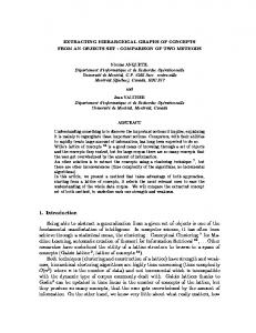
The drawing of directed acyclic graphs (DAG) is widely recognized as a very important task in diverse fields of research and development. Examples include VLSI Design and plant layout [1], graphical user interfaces [2], software and information engineering, project management, visual languages [3], subroutine-call graphs, Interpretative Structural Modeling [4], organization charts, hierarchical relationships, system theory and other research fields. The usefulness of a graph depends on its layout that should be readable, understandable and easy to remember. A fundamental issue in Automatic Graph Drawing is to display hierarchical network structures, as they appear in many applications. The network is transformed into a directed acyclic graph (DAG) that has to be drawn with edges that are strictly monotone with respect to the vertical direction. Many applications imply a partition of the vertices into levels that have to be visualized by placing the vertices that belonging to the same level on a horizontal line. The corresponding graphs are called level graphs, and the drawing of the networks that correspond to this category of graphs means the drawing of level graphs (see [5]). The use of integer coordinates in embedding a graph on the grid has many advantages such as speed, accuracy, and it guarantees automatically that the resultant picture has fairly good properties. A straight line drawing is a grid drawing if each vertex is at a grid point, and the edges are represented as straight-line segments between their endpoints without any edge-intersection. See Figure 1.
Figure 1. Straight line drawing of level planar graph
In [6] introduced genetic algorithms (GAs) with the problem of drawing of level planar graph or hierarchical planar graph, and explored the potential use of GAs to solve this particular problem. They showed that the GAs can help find a layout of levels and hierarchical planar graphs without any crossing edges. Lin and P. Eades [12] show that for each hierarchically planar straight-line drawing of G, where each pair of vertices in the same layer are at least distance 1 apart, has width at least (( 2n 1)! ) where n is the number of vertices in the graph. J. Abello [13] highlighted the main tasks behind the computation of hierarchical graph maps and provided several examples. The techniques have been used experimentally in the navigation of very large graphs. In this paper, we are concerned with drawing of level planar G in the plane such that the vertices of G are represented as grid points, and the edges are represented as straight-line segments between their endpoints without any edgeintersection. An additional objective is to minimize the area of
104 | P a g e www.ijacsa.thesai.org
(IJACSA) International Journal of Advanced Computer Science and Applications, Vol. 3, No. 12, 2012
the rectangular grid in which G is drawn. We introduce new algorithms these find an embedding of G. These new algorithms gives level planar drawing in a rectangular grid with area ( -1)×(k-1), where is the number of vertices in the longest level. This paper is organized as follows. After summarizing the necessary preliminaries in the next section. In the first algorithm, SimpleProperLevel, we explain proper placement for the vertices of a level graph with minimum area in the third section. In the fourth section we explain the second algorithm, FixedDistance, redistribute of the vertices with fixed distance between any two consecutive vertices in the same level on the grid drawing. In section five, DegreeDistance algorithm, redistribute of the vertices on the grid according to its degrees. Finally, Conclusion and references are presented. II.
PRELIMINARIES
Given a directed acyclic graph G (V , E , ) . A leveling of G is a topological numbering of G, where : V mapping the vertices of G to integers such that (v) (u ) 1 for all (u, v) E . G is called a level graph if it has a leveling. If (v) j , then v is a level-j vertex. Let V j 1 ( j ) denote the set of level-j vertices. Each V j is a level of G. If G (V , E , ) has a leveling with k being the largest integer such that V k is not empty, G is said to be a k-level graph. For a k-level graph G, we sometimes write G (V 1 ,V 2 ,...,V k ; E ) .
(A)
(B)
(C)
(D)
Figure 3. Four different embeddings of the same level graph in area 7x4
In Figure 3 we give four different embeddings of the same level graph in a rectangular grid with area 7×4. From Figure 3, it is so easy to observe that for a level graph, there are several embeddings; each one differs in view from the others. The difference in view between several embeddings of the same graph is due to the differences in the distances between each two consecutive levels in the graph, and to the differences in the distances between each two consecutive vertices in each level. According to a certain application, an embedding of a level graph may be more convenient than the other ones, and the convenient embedding may be inconvenient to another application. Jünger, Liepert and Mutzel [16] have given a level planarity test algorithm of G in linear time. Using PQ-tree data structure, Jünger and Liepert [5] have given an algorithm that embeds a level planar graph in linear time, that algorithm was based on a level planarity test in [16].
(a) A level graph.
(b) A hierarchy
Figure 2. Examples of proper level graphs, sources are drawn black
A drawing of G in the plane is a level drawing if the vertices of every V j , 1 j k, are placed on a horizontal line l j {( x, k j ) x R} , and every edge (u, v) E , u V i , v V j , 1 i j k , is drawn as a monotone decreasing curve between the lines l and l . A level drawing of G is called level i
j
planar if no two edges cross except at common endpoints. A level graph is level planar if it has a level planar drawing. A level graph G (V , E , ) is said to be proper, if every edge e E connects only vertices belonging to consecutive levels. Usually, level graph G has sinks and sources placed on various levels of the graph. For example, Figure 2.a, taken from [14],[15], shows a level graph. Hierarchy is a level graph such that all sources belong to the first level V 1 of the graph. As a consequence, we consider only hierarchies with V 1 1 . Figure
By P(v) we will denote the current position of vertex v in the grid, i.e., P(v):=(x(v),y(v)). By P(u,v) we denote the embedding of edge e(u,v), that is, the line segment that connects P(u) with P(v). The following symbols will be used in this paper: hI di D lI
K i
j H,W
is the vertical distance between any two consecutive levels in the graph. is the horizontal distance between any two consecutive vertices in the level V i. is the horizontal distance between any two consecutive vertices in the longest level. is the number of vertices that belong to the level V i. is the number of vertices in the longest level. is the number of levels in given level graph G. is the total degree of the vertices in the level is the degree of the vertex j in the level are the height and the width of the used rectangular grid, respectively.
2.b shows a hierarchy.
105 | P a g e www.ijacsa.thesai.org
(IJACSA) International Journal of Advanced Computer Science and Applications, Vol. 3, No. 12, 2012
In Figure 4 an example to illustrate some of above symbols of given proper level graph, with four levels. The longest level is V 3 with five vertices.
1
EMBEDDING OF GRAPH IN MINIMUM AREA
Let G (V 1, V 2 ,..., V k ; E ) be a given proper level graph with n vertices. An embedding of a level graph can be aesthetic if we redraw the graph by making the distances between each two consecutive vertices, di are equal in the same level, and for every level the distances between each two consecutive levels, hi are equal also. Now we describe the embedding strategy of the first algorithm. Simply, we put di =1 and hi =1 for all levels, but the positions of vertices for each level distributed about the middle point of the width W at this level. The value [W / 2] means that, the integer part of real value W/2. It is clear that, the high of the used rectangular grid, H = h1 + h2 +… hk-1 =k-1 and the width is the total distances di in the longest level. i.e W = di = -1. The complete SimpleProperLevel ( G (V , E , ) ) algorithm can now be described as follows: Algorithm SimpleProperLevel ( G (V , E , ) ); Input: A given level planar graph G(V 1 , V 2 ,..., V k ; E ) with n vertices. Output: An embedding of the level graph G on grid drawing. Begin Let is the number of vertices in the longest level. Now we compute the x- and y-coordinate of V i (v , v ,..., v ), i 1,2,..., k , as follows: 1
2
li
For i=1 to k Begin Let V i (v1 , v2 ,..., vl ) . li is the number of i vertices in level i . For j=1 to li Begin y(vj)= k- i x(vj)= [ / 2] - [ li / 2] + j – 1 End { Now we have a drawing of Gi.} End Output the drawing of G.
Lemma 1: For each 1< i k, when we add V i , then after applying the equations (1)&(2), all neighbors of V i are visible, that the edges between V i and V i 1 do not intersect themselves. Proof: Since G (V 1 ,V 2 ,...,V k ; E ) be a given proper level graph. All neighbors of v V i in Gi-1 are only in the previous level V i 1 . The y-coordinate value is k- i +1 of v V i 1 and ki of any vertex in the consecutive level V i . So, all neighbors of v V i are visible. Since the vertices in the levels are ordered, The x-coordinate values of V i (v , v ,..., v ) are determined
Figure 4. Example of proper level graph k=4.
III.
End.
li
The lemma above implies immediately that adding V i ,1< i k, satisfies the conditions of drawing level graph, as stated in the corollary below. Corollary 1: For each 1< i k, The sub-graphs G (V 1 ,V 2 ,..., V i ; E ) of G remain proper level graph during the algorithm. Theorem 1: SimpleProperLevel algorithm constructs a straight-line embedding of any proper level graph 1 2 k into a ( -1)×(k-1) grid, where is the G(V ,V ,...,V ; E ) number of vertices in the longest level in G. Proof: It is clear that, the height H of drawing grid, H = h1 + h2 +…+ hk-1, since hi =1 as minimum value for all levels, then H =k-1. Also, from equation (1), H= y (v) = k-1 , for any v V 1 . The width is equal to x-coordinate value of vertex number in the longest level. Replace li by in equation (2), W = x (v ) = [ /2] - [ /2] + -1 = -1. Hence, the area used for drawing any given proper level graph is a function of the number of levels and the number of vertices in the longest level. Hence, the proof is completed. Theorem 2: Let G(V 1 ,V 2 ,...,V k ; E ) be given, then SimpleProperLevel algorithm can be computed in linear-time. Proof: We embed one level every one-time run of outerloop in the algorithm. Since k is the number of levels in given level graph G, outer-loop is run in k-times. In inner-loop, every vertex in a level will be visited once. But li is number of vertices in a level V i . Hence the algorithm can be computed in k
li
v i 1 j 1
(1)
2
by equation (2) according to its order in V i , so the edges between V i and V i 1 do not intersect.
j
n times. Hence, the proof is completed.
Notice: We can get more aesthetic embedding of any level graph G by replacing the equation (2) by the following equation: x(vj)= [( +1 )/ 2 ] – [( li +1 )/ 2] + j - 1
(2)
(3)
We can see the difference between using SimpleProperLevel algorithm with the two equations (1&2) and with the two equations (1&3), by embedding the given graph in figure 4. It
106 | P a g e www.ijacsa.thesai.org
(IJACSA) International Journal of Advanced Computer Science and Applications, Vol. 3, No. 12, 2012
is clear that the embedding of Figure (5.b) is more aesthetic than the one given in Figure (5.a).
(a) using equations (1&2).
(b) using equations (1&3)
Figure 5. Example of proper level grap using SimpleProperLevel algorithm
IV.
DISTRIBUTING THE VERTICES WITH CONSTANT DISTANCES
Let G (V 1 , V 2 ,..., V k ; E ) be a given level planar graph with n vertices. The values of the distance di between each two consecutive vertices in a level are computed by dividing the number of vertices in the longest level by the number of vertices in that level i. Its means that di= [ / li ]. Since is greater than or equal to li , then we ensure that di is at least one grid unit . Note that the distance di between each two consecutive vertices is constant value through level i. In order to determine P(vj) , j=1,2,…,li , in the proposed algorithm , when adding a vertex vj , we determine its location in the grid by placing vj such that P(vj)=(x, y), where: y(vj)= k- i x(vj)= [ / 2 - (li –1)*di / 2] + ( j – 1)*di (4) In the equation (4), we will locate the leftmost and rightmost vertices in the longest level to the left and right boundaries of the grid respectively. And for the other levels we keep to equal distances, one between the left boundary and the leftmost vertex and the other one between the right boundary and the rightmost vertex using the term [( / 2 - (li –1)*di / 2]. The output of this algorithm is an embedding of the level graph G on grid drawing with constant distance di and more visible distribution of vertices than the SimpleProperLevel algorithm. The complete ConstantDistance( G (V , E , ) ) algorithm can now be described as follows: Algorithm ConstantDistance ( G (V , E , ) ); Input: A given G(V 1 , V 2 ,..., V k ; E ) with n vertices. Output: An embedding of G on grid drawing. Begin For i=1 to k Begin di= [ / li ] For j=1 to li Begin y(vj)= k- i x(vj)= [ / 2 - (li –1)*di / 2] + ( j – 1)*di End
Output the drawing of G. End. Here we give an example to compare the above algorithms. In this example, we embed a given level graph with seventeen vertex (n=17), sixteen edge (m=16 ), five levels (k=5), and 5 vertices in the longest level which is the level number 2 or 4, ( =5). We embed it using SimpleProperLevel algorithm, where the distance between any two vertices is one unit, see Figure (6.a). Figure (6.b) shows a new embedding of the same level graph after applying of ConstantDistance algorithm, where according to number of vertices in a level the distance di is computed.
(a) SimpleProperLevel algorithm.
(b) ConstantDistance algorithm
Figure 6. Illustration of the distribution of vertices on grid
Theorem 3: ConstantDistance algorithm constructs a straightline embedding of level graph G(V 1 ,V 2 ,...,V k ; E ) into a ( 1)×(k-1) grid. Proof: It is clear that, the high of drawing grid, H = y(v V 1 ) = k-1. The width is equal to x-coordinate value of vertex in the longest level. Since di= [ / li ], put li = in equation (4), then we obtain that W = x(v )= [ / 2 - ( –1)*di / 2] + ( j – 1)*di = [ / 2 - ( –1)*1 / 2] + ( – 1)*1 =
– 1. Hence, the
proof is completed. Theorem 4: Let G(V 1 ,V 2 ,...,V k ; E ) be a given , then ConstantDistance algorithm can be computed in linear-time. Lemma 2: The proper level graph G(V 1 ,V 2 ,...,V k ; E ) can be embedded in any constant area, such that W –1 and H k– 1. Proof: Using ConstantDistance algorithm, Scince W= –1 as minimum width in grid, then we can take di= [(W+1)/li] for W –1 and the equation (4) become x(vj)= [(W+1)/ 2 - (li –1)*di / 2] + ( j – 1)*di Applying the equation (4), we ensure that all vertices are embeds in the width W. On the other hand, the hight is arbitrary positive integer value between any two levels in level graph G. The proof is completed.
End
107 | P a g e www.ijacsa.thesai.org
(IJACSA) International Journal of Advanced Computer Science and Applications, Vol. 3, No. 12, 2012
degree and the degress of its left and right vertices, j ( j 1 j j 1 ) / 3 . Note that if there is not any left or right vertex we consider that the degree of left or right equal to zero. Hence, we can calculate the distance dij between the
(a) W=8 , H=4
vertex vj-1 and vj as a function of total degree i of the level and its weight j , so we can put dij= [ * j / i ]. To overcome confidingness, if dij = 0 , j >1 , we consider dij = 1. In this case, when adding a vertex vj , we determine its location in the grid by placing vj such that P(vj)=(x, y), where: y(vj)= k- i
(b) W=9 , H=4
x(vj)= x(vj-1)+ dij , where dij= [ * j / i ] (5) The complete DegreeDistance( G (V , E , ) ) algorithm can now be described as follows: Algorithm DegreeDistance( G (V , E , ) ); Input: A given G(V 1 ,V 2 ,...,V k ; E ) with n vertices. Output: An embedding of the level graph G on grid drawing. Begin For i=1 to k Begin For j=1 to li Begin dij= [ * j / i ];
(c) W=5 , H=6
If (dij= 0) and ( j>1) Then dij= 1; x(vj)= x(vj-1) + dij ; y(vj)= k- i End End Output the drawing of G. End.
(d) W=10 , H=6
Consequently, from above algorithm, we obtain the following theorem:
Figure 7. Embedding of the same level graph in Figure 6 in 4 different areas.
Figure 7 illustrate lemma 2, embedding of the same level graph in Figure 6 in four different areas. It is so easy to observe that for a level graph, there are several embeddings, each one differs in view from the others and the convenient embedding may be inconvenient to another application. V.
DISTRIBUTION ON GRID USING DEGREES OF VERTICES
In this section we distribute the vertices on the grid according to its degree. So, the distance between each two consecutive vertices is not fixed value in the same level i. Let i is the total degrees of the vertices in the level i, and j is the degree of the vertex j. We calculate the weight
j
of each
vertex in any level i, as the average value of the vertex vj
Theorem 5: DegreeDistance algorithm constructs a straightline embedding of proper level graph G(V 1 ,V 2 ,...,V k ; E ) , which needs a rectangular grid with area at least ( -1) × (k-1) grid and it can be computed in linear-time. Proof: It is clear that, the high of drawing grid, H = y(v V 1 ) = k-1. At least the width is equal to x-coordinate value of vertex in the longest level. Since dij1, From equation (5), we obtain that W = d j –1. Then in this case, embedding of proper level graph G(V 1 ,V 2 ,...,V k ; E ) , which needs a rectangular grid with area at least ( -1)×(k-1) grid. Since we embed one level every one-time run of outer-loop in the algorithm. And k is the number of levels in given level graph G, outer-loop is run in k-times. In inner-loop, every vertex in a level will be visited once in a level V i . Hence the algorithm
108 | P a g e www.ijacsa.thesai.org
(IJACSA) International Journal of Advanced Computer Science and Applications, Vol. 3, No. 12, 2012
can be computed in linear-time times. Hence, the proof is completed.
(a) using SimpleProper-Level algorithm
additional objective is to minimize the area of the rectangular grid in which G is drawn with more aesthetic embedding, that is clearly in the second algorithm. These algorithms run in time O (n) where n is the number of nodes in the graph. It is possible to draw a given level graph within the area W×H. One of the goals of this area of research should be to extend this further, and to determine an optimal width-height tradeoff for grid drawings. Then for any feasible pair (W, H) we could apply a method that gives best drawings on grids of size (W, H). In this paper we introduced several ideas to find an embedding of G in a rectangular grid with area, ( -1)×(k-1), where is the number of vertices in the longest level and k is the number of levels in G. ACKNOWLEDGMENT The authors wish to thank Prof. Abdel Badeeh Salem for his valuable hints and comments. REFERENCES [1]
[2]
[3]
(b) using ConstantDistance algorithm
[4] [5]
[6]
[7] (c) using DegreeDistance algorithm [8] Figure 8. Three different embeddings of the same graph in minimum area.
Here we give an example to compare the above three algorithms. In this example, we embed a given level graph with n=45, m=64, six levels (k=6), and twelve vertices in the longest level which is the level number 4, ( =12). In Figure 8.(a) using SimpleProper-Level algorithm. The output of this drawing has the property that the distance between any two vertices for all vertices is constant and equal to one grid unit. Figure 8.(b) using ConstantDistance algorithm. This drawing has the property that the distance between any two vertices in the same level are constant and is equal to one or more one grid unit. In Figure 8.(c) using DegreeDistance algorithm. The output of this drawing depends on the degree of the vertex and its neighbors for all vertices.
[9] [10]
[11]
[12]
[13] [14]
VI.
CONCLUSION
In this paper, we introduced new three algorithms for embedding a proper level graph on a grid with minimum width. These algorithms keep a proper placement for the nodes that belonging to the same level for each level in the graph. An
[15] [16]
F. Chung, F. Leighton and A. Rosenberg, “Embedding Graphs in Books: A Layout Problem with Applications to VLSI Design”, SIAM Journal Discrete Mathematics, 8, pp. 33-58, 1987. G. Di Battista, P. Eades, R. Tamassia and I. Tollis, “Algorithms for Drawing Graphs: Annotated Bibliography”, Computational Geometry, Theory Applications, 4, pp. 235-282, 1994. S. Bhatt and F. Leighton, “A Framework for Solving VLSI Graph Layout Problems”, Journal of Computer and System Systems Sciences 28, pp. 300-343, 1984 P. Eades and X. Lin, “How to Draw a Directed Graph”, Proceeding IEEE on Visual Languages, (VL ’89), pp. 13-17, 1989. M. Jünger and S. Liepert, "Level Planar Embedding in Linear Time", Technical Report 99-374, Institut für Informatik, Unversität zu Köln, 1999. Ahmed A. A. Radwan, Mohamed A. El-Sayed and Nahla F. Omran, “Hybrid GA for Straight-Line Drawings of Level Clustered Planar Graphs”, IJCSI International Journal of Computer Science Issues, Vol. 8, Issue 4, No 2, pp. 229- 235, July 2011. A. Yamaguchi and A. Sugimoto, “An Approximation Algorithm for the Two-Layered Graph Drawing Problems”, COCOON ’99, (Lecture Notes in Computer Sciences, 1627), pp. 81-91, 1991. C. Batini, L. Furlani and E. Nardelli, “What is a Good Diagram? A Pragmatic Approach”, Proceeding Of the 4th International Conference on Entity-Relationship Approach, pp. 312-319, 1985. C. Esposito, “Graph Graphics: Theory and Practice”, Computer and Mathematics with Applications 15 (4), pp. 247-253, 1988. H. Purchase, R. Cohen and M. James, “Validating Graph Drawing Aesthetics”, Proceeding of Symposium on Graph Drawing, GD ’95 (Lecture Notes in Computer Sciences, 1027), pp. 435-446, Springer, 1996. A. A. A. Radwan, M. R. Girgis and A. A. Ghanem, “A Study of the Area of Drawing Level Graphs”, International Journal of Applied Mathematics, 5(4), pp. 363-375, 2001. X. Lin and P. Eades, “Towards area requirements for drawing hierarchically planar graphs”, Theoretical Computer Science, Volume 292, Issue 3, Pages 679-695, 31, 2003. J. Abello, “Hierarchical graph maps”, Computers & Graphics, Volume 28, Issue 3, Pages 345-359, June 2004. M. J¨unger and S. Leipert, "Level Planar Embedding", Journal of Graph Algorithms and Applications, vol. 6, no. 1, pp. 67-113, 2002. S. Liepert, “Level Planarity Testing an Embedding in Linear Time”, Ph.D. thesis, Unversität zu Köln ,1998. M. Jünger, S. Liepert and P. Mutzel, “Level Planarity Testing in Linear Time” , In S. Witesides, editor, Graph Drawing '98, volume 1547 of Lecture Notes in Computer Science, Springer Verlage, 224-237, 1998.
109 | P a g e www.ijacsa.thesai.org