Abstract. Landfills of material contaminated by depleted uranium and other low-level radioactive waste must be isolated from the biosphere for a sufficiently long ...
Journal of Earth Sciences and Geotechnical Engineering, vol. 3, no. 3, 2013, 109-125 ISSN: 1792-9040 (print), 1792-9660 (online) Scienpress Ltd, 2013
Hydraulic Properties of Smectite Clays from Iraq with Special Respect to Landfills of DU-contaminated Waste Laith Al-Taie1, Roland Pusch2, Nadhir Al-Ansati3 and Sven Knutsson4
Abstract Landfills of material contaminated by depleted uranium and other low-level radioactive waste must be isolated from the biosphere for a sufficiently long time. This can be effectively made in desert climate by collecting contaminated waste in suitable areas confined by tight embankments and covering them with very tight clay liners protected from desiccation and erosion by suitably composed filters and coarse rock fill. Examples of design principles and construction are described in the paper. The clay liners are made of air-dry expanding clay that can be found in sufficient quantities in Iraq and that provide very good tightness at low cost. The construction technique is well known from various projects. Keywords: smectite, depleted uranium, hydraulic conductivity, hazardous waste
1
Introduction
Soil with radioactive contaminants needs to be isolated from groundwater and living species for sufficient time, which is about 300 years for low-level waste from nuclear plants and even longer for waste with long-lived radionuclides [1]. Climatic conditions, that can represent arctic to desert environments, need to be considered in the design and construction phases and short-term extreme conditions, like very heavy rainfall for a day or two every fiftieth year may have to be included in the scenarios taken as basis of the design work. Top covers of waste piles shall therefore contain an erosion-protective drain layer over the engineered barrier that shall minimize infiltration of rain and melt water into and through the waste. The barrier below the erosion-protecting top cover is
1
Luleå University of Technology, Luleå, Sweden. Civil Engineering Dept., College of Engineering, University of Mosul. Iraq. 2 Luleå University of Technical, Luleå, Sweden. 3 Luleå University of Technical, Luleå, Sweden. 4 Luleå University of Technical, Luleå, Sweden.
110
Laith Al-Taie, Roland Pusch, Nadhir Al-Ansati and Sven Knutsson
commonly proposed of a low-permeability clay liner of smectitic clay and a similar layer suggested to form the base of the waste pile. If maintenance of the landfill in the form of drainage and treatment of water that has percolated the waste is required, the respective organization or authorities responsible for this must see to that the function of the landfill is acceptable for the long time considered. If, on the other hand, no monitoring, repair or reconstruction are planned the landfill must perform automatically. This latter principle is preferable from economic points of view if a durable barrier system can be made and various attempts for this have been comprehensively described in the literature [2,3]. The aim can be to design the top liner so that infiltrated precipitation is retained until evaporation recycles the water back to the atmosphere hence preventing irreparable desiccation, but it is realized that the whole wetting/drying process is a key issue of great complexity and further complexed by entering electrolytes and freezing/thawing. A fundamental matter is the hydraulic performance of smectitic clay for the special case of complete water saturation with respect to the microstructural constitution and the impact of hydraulic gradients. They are in focus of the present paper.
2
Principle of Design of DU Waste Landfill
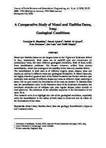
2.1 Legislation and Criteria Waste with very low content of radioactive matter (LLW) shall be isolated from the biosphere for 300 and 500 years according to IAEA and NRC regulations [1,4]. The following criteria are taken as a basis of the design: Disposal within a defined area within which there must be no wells for drinking water or irrigation. Confinement by construction of stable and tight embankments or dikes. The ideal function of the disposal site is to design the top liner so that infiltrated precipitation is retained until evaporation recycles the water back to the atmosphere [5]. If this can be achieved there is no need for constructing pipe systems for collecting percolate and clean it and such a solution is aimed at for the DU waste landfill in Iraq. Figure 1 shows a cross section of such an arrangement.
2.2 Function of a Landfill in Desert Area 2.2.1 Principle The landfill is constructed so that no maintenance will be needed for the required time, at least 300 years, of isolation of the waste. The conditions are that no human activities will take place that can cause deterioration, i.a. excavation for use of engineered barriers and that very significant exogenic impact, like earthquakes of very high magnitude, does not take place.
Hydraulic Properties of Smectite Clays from Iraq
111
Supporting dikes
Rock/boulder
Protective layer
Regulating layer
Gravel
Geomembrane
Contaminated soil
Sand/silt
Clay liner
Permeable soil
Figure 1: Cross sectional profile of a suggested landfill confining contaminated soil with Depleted Uranium. 2.2.2 Site selection The construction site should be in an elevated area where precipitation of rain or melt water cannot accumulate and cause flooding, and where wind-driven sand migration is not expected to cause significant erosion or lead to considerable sand drift. Areas with significant seismic or tectonic events are known to take place shall be avoided. The disposal area should be on dense sand, which minimizes settlement and provides effective drainage of occasionally occurring rainfall. Cold conditions causing freezing shall be avoided. 2.2.3 Construction sequence The construction of a landfill of the type shown in Figure 1 starts by evening the natural ground and placing a base layer of coarser material that is effectively compacted. A filter consisting of silt/sand/gravel is then placed and compacted upon which embankments are constructed for supporting the waste to be filled. A bottom liner of clay material can then be placed over the entire area, reaching up on the sloping embankments but this may not be required depending on the stipulations by the authorities. The next phase is placement of DU-contaminated soil in layers that are compacted by vibrating rollers, the shape of the fill being a ridge with sloping sides. The compacted waste is covered by a top liner of smectitic clay that is suitably in the form of air-dry granulate. The inclination of the sloping waste fill must not exceed the angle of internal friction of the clay layer, which is covered by a filter of silt/sand/gravel, with rock blocks for erosion protection of the clay liner being the uppermost barrier. 2.2.4 Evolution A normal scenario in desert areas is that the temperature rises to more than 47°C in daytime [6], by which the upper barriers become heated but sufficient height of the erosion protection and filter will keep the temperature of the clay liner at much lower temperature. Three scenarios can appear respecting the clay in the top liner: No precipitation keeps the initial water content of the clay constantly at 5-10 percent by weight through days, weeks, months and years,
112
Laith Al-Taie, Roland Pusch, Nadhir Al-Ansati and Sven Knutsson
Rainfall for a limited period of time causes wetting and homogenization of the clay, which will self-seal and stop migration of infiltrated water. Intermediate dry periods will cause reverse migration of water, ultimately leading to the original state with microstructurally heterogeneous clay with a water content of 5-10 percent by weight through days, weeks, months and years etc. Very long, intense rain can create an artificial groundwater table in the filter covering the top liner and create complete water saturation of the clay in the top liner. Taking the lower boundary of the clay to have no water pressure, the hydraulic gradient across the clay will be i=H/d, where H is the water pressure on the upper boundary of the liner and d its thickness. For practically selected dimensions i will be in the range of 1-50 m/m, with duration of the highest gradients ranging from days to weeks while the lower will dominate and become negative in periods of draught because of capillary suction. The most critical conditions with respect to percolation of the top liner will be those prevailing in paragraph 3, with the clay liner being completely water saturated. This is the case that we will examine in the paper.
3
Hydration and Permeation of Clay Liners
3.1 General The amount of water that is infiltrated into the top liner of a waste pile and that penetrates the waste mass and the bottom clay liner per time unit depends primarily on the water pressure exerted on the liner. The hydration of it is transient since it depends on the varying access to water from the overlying drain layer, the water pressure and relative humidity of the air in the voids of this layer and in the clay layer. Taking the clay to consist of smectitic clay, like bentonite, and assuming that access to water from the overlying drain layer is unlimited, one can assume that hydration of the clay takes place by diffusive migration of water [7]. The time for saturation of the clay liner is very long as illustrated by the fact that a 20 mm thick layer of smectite clay with a dry density of 1300 kg/m3 is almost 12 days by one-sided wetting if the diffusion coefficient is 3x10⁻¹⁰ m2/s, which is typical for dense smectite-rich clay. Considering that rain- and snowfall and hence access to water for uptake by the clay are intermittent and that draught will occur in periods, the actual time for complete saturation will be several tens of years and even more for a few decimetre thick smectite clay layer. After water saturation of the top liner it will be percolated under the hydraulic gradient that is produced when a pressure head develops in the overlying drain layer. Prediction of the percolation rate is trivial, while definition of pressure heads and their persistence requires estimation of the water balance based on statistical precipitation data. As a very conservative case one can assume that the water level in the drain layer on top of the upper clay liner is maintained at a height over the clay liner that corresponds to 100% of the annual precipitation, which is taken here as 1 m. Using Darcy’s law the percolation rate is: v=K x i
(1)
where: v=flow rate in m/s, K=hydraulic conductivity in m/s and i=hydraulic gradient (m/m)
Hydraulic Properties of Smectite Clays from Iraq
113
Taking as an example K as 10-11 m/s, which is achievable by using smectitic clay with a density of about 2000 kg/m3 at water saturation and a thickness of the clay layer of 1 m one has i=1 and v=10-11 m/s, which means that a flow-transported water molecule moves by about 10 mm in 300 days and that it would take 100 years for it to migrate through a 1 m thick clay layer. Such a clay exerts a swelling pressure which can cause upheaval of the overlying soil layers if it exceeds the effective pressure caused by these layers. For a fully water saturated smectite-rich clay with a dry density of 1590 kg/m3, yielding a bulk density of about 2000 kg/m3 after water saturation, the swelling pressure would be disastrous, i.e. 10 MPa. It is therefore required to use less smectite-rich clay and compact them to lower density. Taking the overburden to have an average density of 2000 kg/m3 and be 5 m high it will exert a pressure on the upper boundary of the top liner of 100 kPa which is hence the upper limit of the swelling pressure exerted by the liner.
4
Iraqi Candidate Clay for Use in Top Liners
4.1 Location and Identification Green and Red smectite rich clays were selected from Mosul City located in the northern part of Iraq. The clays belong to the Fatha formation, [8]. This formation is of Lower Miocene age and is composed of alternating beds of limestones, gypsum and green and red clays and siltstones. These beds are very thick toward the upper most part of the formation. The formation in its type locality is few hundred meters thick [9]. The green clay was extracted from a thick layer (at least 2 m) exposed near the ground surface in Qadia district, Figure 2, which appeared as hard light-green coloured pieces (Green clay). The Red clay had the form of brown/red hard pieces sampled from a thick layer (at least 3 m) about 4 km SSE from the place where the Green clay is located.
4.2 Characterization The two smectite clays were crushed by means of impact before doing laboratory tests. The crushing product was sorted on a 1 mm sieve and further disaggregated by ultrasonic treatment before carrying out consistency limits, grain size analysis and specific gravity tests [10]. All the laboratory work was conducted according to the American Society for Testing and Materials (ASTM) or British Standard (BS). 4.2.1 Granulometry Both wet sieving and pipette analysis were conducted, the grain size analysis being shown in Figure 3. Table 1 shows some physical properties of the Green and Red clays. Both were classified as CH soils according to the unified soil classification system (USCS). Further, clay activity characterization (Plasticity index/fraction