May 25, 2010 - This implies a possibility of a âtripletâ spin-valve effect: at temperatures above ... by reversing the magnetization direction of the F1 or. F2 layer.
Pis’ma v ZhETF
Superconducting triplet spin valve Ya. V. Fominov + , A. A. Golubov ∗ , T. Yu. Karminskaya ∇, M. Yu. Kupriyanov ∇ , R. G. Deminov � , L. R. Tagirov � ∗
+ L. D. Landau Institute for Theoretical Physics RAS, 119334 Moscow, Russia Faculty of Science and Technology and MESA+ Institute of Nanotechnology, University of Twente, P.O. Box 217, 7500 AE Enschede, The Netherlands ∇ Nuclear Physics Institute, Moscow State University, 119992 Moscow, Russia � Physics Faculty, Kazan State University, 420008 Kazan, Russia
arXiv:1002.2113v2 [cond-mat.supr-con] 25 May 2010
Submitted 25 May 2010
We study the critical temperature Tc of SFF trilayers (S is a singlet superconductor, F is a ferromagnetic metal), where the long-range triplet superconducting component is generated at noncollinear magnetizations of the F layers. We demonstrate that Tc can be a nonmonotonic function of the angle α between the magnetizations of the two F layers. The minimum is achieved at an intermediate α, lying between the parallel (P, α = 0) and antiparallel (AP, α = π) cases. This implies a possibility of a “triplet” spin-valve effect: at temperatures above the minimum TcTr but below TcP and TcAP , the system is superconducting only in the vicinity of the collinear orientations. At certain parameters, we predict a reentrant Tc (α) behavior. At the same time, considering only the P and AP orientations, we find that both the “standard” (TcP < TcAP ) and “inverse” (TcP > TcAP ) switching effects are possible depending on parameters of the system. Published as: JETP Letters 91, 308 (2010) [Pis’ma v ZhETF 91, 329 (2010)] PACS: 74.45.+c, 74.78.Fk, 75.70.Cn, 75.30.Et
fect [9, 10, 11, 13] with TcP > TcAP (i.e., ∆Tc < 0). The most advanced calculations within the proximity effect theory, which take into account the triplet components of the superconducting pairing [14], demonstrate only the standard switching [3, 15] with Tc monotonically increasing from the P to AP configuration [3]. Additional physical mechanisms like spin imbalance effect [9, 11] or magnetic domain structure [10, 12] should be recruited to explain the inverse spin-valve effect in the studied F1/S/F2-type structures.
In superconducting spin valves with the layer sequence F1/S/F2 the superconducting transition temperature Tc of the system can be controlled by mutual alignment of magnetizations M1,2 of the two ferromagnetic layers F1 and F2. Therefore, at a temperature T fixed inside the range of Tc variation, there is an opportunity for switching the superconductivity on and off by reversing the magnetization direction of the F1 or F2 layer. Model calculations have shown that the transition temperature TcAP for the antiparallel (M1 ↑↓ M2 ) orientation of the F1 and F2 magnetizations should be higher than the transition temperature TcP for the opposite case (M1 ↑↑ M2 ) [1, 2, 3]. The situation with this order of Tc ’s (i.e., TcP < TcAP ) is commonly referred to as the “standard” switching (see, e.g., [4]), and the switching in this case actually occurs at temperatures T such that TcP < T < TcAP . The basic physical reason for the difference ∆Tc = TcAP − TcP > 0 is partial compensation of the pair-breaking ferromagnetic exchange field, if the magnetizations of the F1 and F2 layers are aligned antiparallel.
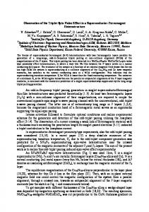
A bit earlier an unconventional spin-valve-like S/F1/F2 structure was theoretically proposed in [16] to control the superconducting Tc in the S layer by mutual alignment of the magnetizations of the two adjacent ferromagnetic layers F1 and F2. The authors of [16] argued that TcP < TcAP in their system because of partial cancelation of the pair-breaking exchange fields just within the magnetic F1/F2 subsystem of the structure, thus predicting the standard switching as in the interleaved F1/S/F2 structure. The S/F1/F2 structures are much less investigated experimentally [8, 17], and the experiments indicate the standard switching effect [16] with the maximal size of about 200 mK. In this Letter we study the critical temperature of a S/F1/F2 trilayer at arbitrary angle between the in-plane magnetizations of the ferromagnetic layers (see Fig. l). We demonstrate that this structure allows not only the standard but also inverse spinswitching effect. Moreover, we show for the first time
Several experimental groups have published results on superconducting spin valves of the F1/S/F2 type [4, 5, 6, 7, 8, 9, 10, 11, 12, 13]. The experimental results turned out to be controversial. Some studies of F1/S/F2 structures have shown the standard spin-valve effect [4, 5, 6, 7, 8] with the maximum shift ∆Tc ≈ 41 mK reported for the Ni/Nb/Ni trilayer in [7]. However, some experiments revealed the “inverse” spin-valve ef1
2
Ya. V. Fominov, A. A. Golubov, T. Yu. Karminskaya, et al.
S
dS
F1
dF
z
F2 infinitely thick
y x
z
y x
Fig. 1. S/F1/F2 trilayer. The S/F1 interface corresponds to x = 0. The thick arrows in the F layers denote the exchange fields h lying in the (y, z) plane. The angle between the in-plane exchange fields is α.
TcTr
that the minimal critical temperature of the structure is achieved at a noncollinear alignment of the magnetizations, when the long-range triplet component of the superconducting pairing is generated. Since TcTr is lower than both TcP and TcAP , this offers a possibility of a “triplet spin-valve effect” never reported before. 1. Model. We consider the S/F1/F2 structure in the dirty limit, which is described by the Usadel equations. Near Tc , the Usadel equations are linearized and contain only the anomalous Green function fˇ [14, 18]: i sgn ω � D d2 fˇ ˆ fˇ + ∆ˆ τˆ0 (hσ), τ1 σ ˆ0 = 0. (1) − |ω|fˇ − 2 2 dx 2 Here, fˇ is a 4×4 matrix, τˆi and σ ˆi are the Pauli matrices in the Nambu-Gor’kov and spin spaces, respectively, D is the diffusion constant, and ω = πTc (2n + 1) with integer n is the Matsubara frequency. The exchange field in the middle F1 layer is along the z direction, h = (0, 0, h), while the exchange field in the outer F2 layer is in the yz plane: h = (0, h sin α, h cos α). The angle α changes between 0 (parallel configuration, P) and π (antiparallel configuration, AP). The order parameter ∆ is real-valued in the superconducting layer, while in the ferromagnetic layers it is zero. In general, the diffusion constant D acquires a proper subscript, S or F, when Eq. (1) is applied to the superconducting or ferromagnetic layers, respectively. However, for simplicity we take them equal in this paper, because this assumption does not influence qualitative behavior of Tc (α). The Green function fˇ can be expanded into the following components: fˇ = τˆ1 (f0 σ ˆ0 + f3 σ ˆ3 + f2 σ ˆ2 ) ,
(2)
where f0 is the singlet component, f3 is the triplet with zero projection on the z axis, and f2 is the triplet
with ±1 projections on z (the latter is present only if α 6= 0, π). The singlet component is even in frequency (and real-valued), while the triplet ones are odd (and imaginary): f0 (−ω) = f0 (ω), f3 (−ω) = −f3 (ω), and f2 (−ω) = −f2 (ω), which makes it sufficient to consider only positive Matsubara frequencies, ω > 0. As we show below, the problem of calculating Tc can be reduced to an effective set of equations for the singlet component in the S layer: the set includes the self-consistency equation and the Usadel equation, � X �∆ TcS ∆ ln (3) = 2πTc − f0 , Tc ω ω>0 D d2 f0 − ωf0 + ∆ = 0, 2 dx2 with the boundary conditions df0 df0 . = 0 = W f0 , −ξ dx dx x=0 x=−dS
(4)
(5)
p Here TcS and ξ = D/2πTcS are the superconducting transition temperature and coherence length for an isolated S layer, and we assume that the S layer occupies the region −dS < x < 0 (see Fig. 1). This is exactly the problem for which the multi-mode solution procedure (as well as the fundamental-solution method) was developed in [19] and then applied to F1/S/F2 spin valves in [3]. We only need to determine the explicit expression for W in Eq. (5), solving the boundary problem for the S/F1/F2 structure. 2. Solution of the model. To simplify derivations, while keeping the essential physics, we consider the middle ferromagnetic layer F1 of arbitrary thickness (0 < x < dF ) but the outer ferromagnetic layer F2 being semi-infinite (dF < x < ∞). The Usadel equation (1) generates the following characteristic wave vectors: r r q 2ω h , kh = , k˜h = kω2 + 2ikh2 . (6) kω = D D Only kω appears in the solution for the S layer, while the F-layers’ solutions are described by kω , k˜h , and k˜h∗ . Since the exchange energy is usually larger than the superconducting energy scale, h ≫ Tc , the kω mode in the ferromagnetic layers (arising at noncollinear magnetizations) represents the long-range triplet component [14], which plays the key role in the present study. In the S layer the solution of Eq. (1) is: 0 f0 (x) f0 (x) cosh (kω (x + dS )) . (7) f3 (x) = 0 + A cosh (kω dS ) B 0 f2 (x)
3
Superconducting triplet spin valve The singlet component f0 (x) in the S layer cannot be written explicitly, since it is self-consistently related to the (unknown) order parameter ∆(x) by Eqs. (3)-(4). Our strategy now is to obtain the effective boundary conditions (5) for f0 (x), eliminating all other components in the three layers. In the middle F1 layer the solution of Eq. (1) reads: 0 f0 (x) 0 f3 (x) = C1 0 cosh (kω x) + S1 0 sinh (kω x) + f2 (x)
1 1 −1 1 � � � � ˜ +C2 1 cosh kh x + C3 1 cosh k˜h∗ x + 0 0 −1 1 � � � � ˜ +S2 1 sinh kh x + S3 1 sinh k˜h∗ x . (8) 0
0
Finally, the solution in the semi-infinite, outer F2 layer is built only from descending modes: 0 f0 (x) f3 (x) = E1 − sin α exp (−kω (x − dF )) + f2 (x)
cos α 1 � � + E2 cos α exp −k˜h (x − dF ) + sin α −1 � � + E3 cos α exp −k˜h∗ (x − dF ) .
(9)
sin α
We will use the simplest, perfect-transparency boundary conditions at the S/F1 and F1/F2 interfaces (the case γ = 1 and γB = 0 in the notations of [20]): dfi dfi = . (10) fi |left = fi |right , dx left dx right Altogether there are 12 boundary conditions at the two interfaces (S/F1 and F1/F2). We are mainly interested in one of them, determining the derivative of the singlet component on the S side of the S/F1 interface (x = 0): df0 = 2 Re(k˜h S2 ). (11) dx x=0
The remaining 11 boundary conditions form a system of 11 linear equations for 11 coefficients entering Eqs. (7)-(9). The solution of this system is nonzero due to f0 (0) coming from Eq. (7) and entering the “right-hand
0.6 0.5
W(0)-W(
0.4
)
W(0)
0.3 0.2 0.1 0.0 -0.1 0
1
2
3
4
5
6
2 kh dF
Fig. 2. Dependence of W (0) − W (π), Eq. (12), on the thickness dF of the F1 layer. Positive values of this oscillating function correspond to stronger suppression of superconductivity at the P alignment (the standard switching effect), while negative values correspond to stronger suppression of superconductivity at the AP alignment (the inverse switching effect).
side” of the system. Finding the S2 coefficient [which is proportional to f0 (0)], we substitute it into Eq. (11) and thus explicitly find W entering the effective boundary conditions (5). 3. Analysis of the solution. After reducing the problem to Eqs. (3)-(5), all the information about the two F layers is contained in the single real-valued function W . This function makes f0 (x) bend at the S/F1 interface, hence the larger W , the stronger Tc is suppressed. The explicit expression for W (α) is very cumbersome and we do not write it here. However, certain analytical development (as well as complete numerical analysis) is possible. For the analytical consideration, we make an additional assumption of Tc ≪ h, which implies kω ≪ kh . For the collinear cases (α = 0 and α = π) we then find W (0) = 2kh ξ and √ 2 sin(2kh dF + π/4) − e−2kh dF , W (0) − W (π) = 2kh ξ sinh(2kh dF ) + cos(2kh dF ) (12) which oscillates as a function of dF , changing its sign (see Fig. 2). Thus, as a result of interference in the middle F1 layer, we can either have the standard spinswitching effect with TcP < TcAP [when the pair-breaking at the P alignment is stronger than at the AP alignment of magnetizations, i.e., at W (0) − W (π) > 0 as in the range 2kh dF < 3π/4 in Fig. 2] or the inverse spinswitching effect with TcP > TcAP [at W (0)−W (π) < 0 as in the range 3π/4 < 2kh dF < 7π/4 in Fig. 2]. Note that the amplitude of the inverse effect is notably smaller compared with the standard one. The analytical calcu-
4
Ya. V. Fominov, A. A. Golubov, T. Yu. Karminskaya, et al.
Tc (
0.33
dS /
S
Tc(
0.30
)
dF /
= 2.75 0.25
Tc / TcS
0.27
0.24
dF /
F
= 0;
dF /
F
= 0.15
dF /
F
= 0.73
dF /
F
= 1.10
0.20
Tc / TcS
0.30
dF /
2
0.21
30
60
90
S
= 2.75
dS /
F
S
= 2.69
dF /
F
= 0.40,
dS /
S
= 2.75
dF /
F
= 0.40,
dS /
S
= 2.66
1 2
2 4
0.05
4 0
dS /
= 0.73,
0.15
1
0.15
= 0.73,
3
0.10
0.18
)
F
3 120
150
4 0.00 180
Angle between magnetizations (degrees)
Fig. 3. Critical temperature Tc vs. the misalignment angle α for various thicknesses of the F1 layer. We took h/πTcS = 6.8; all other parameters are shown in the figure. In the cases dF = 0 and dF = ∞, which are physically equivalent (curve “1”), Tc does not depend on α. Curves “2” and “4” correspond to the standard and inverse switching effects, respectively. Curve “3” demonstrates the triplet spin-valve effect. The coherence lengths ξS and ξF were taken equal (denoted by ξ in the text) in order to present our main results in the simplest possible case. At α = 0 all the curves coincide, since in this case the F part of the system is physically equivalent to a single half-infinite F layer.
lation of the second derivatives of W (α) at α = 0 and π (the first ones are zero) shows that under the above assumption, both the collinear alignments represent local minima of W (α). This means that Tc (α) decreases as the configuration deviates from the P or AP alignment. Therefore, Tc (α) is nonmonotonic, and the minimal Tc must be achieved at some noncollinear configuration of magnetizations at α 6= 0, π. The analytical results obtained at kω ≪ kh are illustrated and extended by numerical calculations at arbitrary relation between kω and kh . Figure 3 shows dependence of the transition temperature Tc on the angle α between the magnetizations. We see that at small thicknesses dF of the middle ferromagnetic layer F1, the switching effect is standard, while at larger dF the effect is inverse (TcP > TcAP ). Moreover, when the F1 layer thickness is around a half of the coherence length ξ, the minimal critical temperature TcTr at noncollinear orientations is significantly lower that both TcP and TcAP — this case corresponds to the triplet spin-valve effect. Note that depending on the parameters of the system, the minimum of Tc (α), predicted analytically, can shift
0
30
60
90
120
150
180
Angle between magnetizations (degrees)
Fig. 4. Tc (α) at various dF and dS . Curve “1” coincides with curve “3” in Fig. 3. Curves “2” and “4” demonstrate the reentrant behavior, in which case the triplet spin-valve effect takes place even at T = 0.
to a close vicinity of either α = 0 or α = π, becoming shallow and indistinguishable. Figure 4 demonstrates the possibility of reentrant Tc (α) dependence. In this situation the triplet spinvalve effect takes place even at T = 0. 4. Discussion. The physical interpretation of the triplet spin-valve effect can be given as follows: at the collinear configurations, both the singlet component f0 and the zero-projection triplet component f3 of the pairing function are short-ranged (with the characteristic penetration depth of the order of kh−1 ), so that at kh−1 ≪ dF the middle F1 layer plays a role of a shield separating the S layer from the ferromagnetic half-space F2. When the angle between magnetizations declines from the collinear configurations, the long-range triplet component f2 of the pairing function is generated [14]. Then, the S layer becomes effectively coupled by this long-range triplet component to the semi-infinite ferromagnetic F2 layer. The pair-breaking in the S layer enhances, giving rise to more effective suppression of superconducting Tc . In other words, we can say that the Tc suppression is due to “leakage” of Cooper pairs into the ferromagnetic part. In this language, the generation of the long-range triplet component opens up an additional channel for this “leakage”, hence Tc is suppressed stronger. In order to supply the qualitative picture by more quantitative details, we can find the amplitudes of different components at the S/F1 interface in the limit of kω ≪ kh and large dF . This can be done analytically
Superconducting triplet spin valve from the boundary conditions which produce the linear system of equations for the coefficients entering Eqs. (7)(9). We find that in the limit of dF ≫ kω−1 , kh−1 , the amplitudes of the long-range triplet components near the S/F1 interface (which are given by C1 , S1 , and B) are suppressed by the factor e−kω dF −kh dF which has a clear physical interpretation. The long-range components are generated from the short-range ones at the F1/F2 interface (i.e., at x = dF ), where electrons “feel” inhomogeneous magnetization. Therefore, the long-range contribution at the S/F1 interface is obtained as a result of a “wave” that goes from the S/F1 interface as a shortrange component with the wave vector kh and returns after reflection at the F1/F2 interface as a long-range component with the wave vector kω . At the same time, the self-consistency equation (3) that determines Tc , contains only the singlet short-range component. Therefore, the influence of the long-range components on Tc is indirect: the long-range components influence Tc only through their influence on the singlet component. We find that while the difference between W (that encodes the information about the suppression of Tc ) for the P and AP cases is suppressed as e−2kh dF (the shortrange components go from the S/F1 to F1/F2 interface and back), the changes in W due to noncollinear magnetizations contain the same exponential, e−2kh dF . Of course, the influence of the long-range triplet components is contained in prefactors but no long-ranged exponential (with kω instead of kh ) appears in W , because W still originates from the short-range components. In conclusion, we have considered a mesoscopic S/F1/F2 structure composed of a superconducting layer S, a ferromagnetic layer of arbitrary thickness F1, and a ferromagnetic half-space F2. We have demonstrated that the structure exhibits different relations between the critical temperatures in the parallel and antiparallel configuration: both the standard (TcP < TcAP ) and inverse (TcP > TcAP ) switching can be realized depending on the system’s parameters. At the same time, our main result is that TcTr at noncollinear magnetizations is lower than both TcP and TcAP, which makes this system a triplet spin valve. Possible experimental observation of a nonmonotonic (like curve “3” in Fig. 3 or curves “1” and “3” in Fig. 4) or even reentrant (like curves “2” and “4” in Fig. 4) behavior of Tc (α) could be a signature of existence of the long-range triplet superconducting correlations [14] in SF hybrid structures. We are grateful to I. A. Garifullin and A. S. Sidorenko for discussions stimulating this study, to O. V. Nedopekin for assistance in numerical calculations, and to M. V. Feigel’man and V. V. Ryazanov for discussion of the results. This work was supported by
5
the RFBR (projects 07-02-00963-a, 09-02-12176-ofi m, 09-02-12260-ofi m, and 10-02-90014-Bel a), by the NanoNed (project TCS7029), and by the Russian Federal Agency of Education (contract NK-529P).
1. L. R. Tagirov, Phys. Rev. Lett. 83, 2058 (1999). 2. A. I. Buzdin, A. V. Vedyayev, and N. V. Ryzhanova, Europhys. Lett. 48, 686 (1999); A. I. Buzdin, Rev. Mod. Phys. 77, 935 (2005). 3. Ya. V. Fominov, A. A. Golubov, and M. Yu. Kupriyanov, Pis’ma Zh. Eksp. Teor. Fiz. 77, 609 (2003) [JETP Lett. 77, 510 (2003)]. 4. I. C. Moraru, W. P. Pratt, Jr., and N. O. Birge, Phys. Rev. B 74, 220507(R) (2006). 5. J. Y. Gu, C.-Y. You, J. S. Jiang et al., Phys. Rev. Lett. 89, 267001 (2002). 6. A. Potenza and C. H. Marrows, Phys. Rev. B 71, 180503(R) (2005). 7. I. C. Moraru, W. P. Pratt, Jr., and N. O. Birge, Phys. Rev. Lett. 96, 037004 (2006). 8. G. Nowak, H. Zabel, K. Westerholt et al., Phys. Rev. B 78, 134520 (2008). 9. A. Yu. Rusanov, S. Habraken, and J. Aarts, Phys. Rev. B 73, 060505(R) (2006). 10. R. Steiner and P. Ziemann, Phys. Rev. B 74, 094504 (2006). 11. A. Singh, C. S¨ urgers, and H. v. L¨ ohneysen, Phys. Rev. B 75, 024513 (2007). 12. D. H. Kim and T. J. Hwang, Physica C 455, 58 (2007). 13. P. V. Leksin, R. I. Salikhov, I. A. Garifullin et al., Pis’ma Zh. Eksp. Teor. Fiz. 90, 64 (2009) [JETP Lett. 90, 59 (2009)]. 14. F. S. Bergeret, A. F. Volkov, and K. B. Efetov, Phys. Rev. Lett. 86, 4096 (2001); Rev. Mod. Phys. 77, 1321 (2005). 15. J. Linder, M. Zareyan, and A. Sudbø, Phys. Rev. B 79, 064514 (2009). 16. S. Oh, D. Youm, and M. R. Beasley, Appl. Phys. Lett. 71, 2376 (1997). 17. K. Westerholt, D. Sprungmann, H. Zabel et al., Phys. Rev. Lett. 95, 097003 (2005). 18. D. A. Ivanov and Ya. V. Fominov, Phys. Rev. B 73, 214524 (2006). 19. Ya. V. Fominov, N. M. Chtchelkatchev, and A. A. Golubov, Pis’ma Zh. Eksp. Teor. Fiz. 74, 101 (2001) [JETP Lett. 74, 96 (2001)]; Phys. Rev. B 66, 014507 (2002). 20. M. Yu. Kuprianov and V. F. Lukichev, Zh. Eksp. Teor. Fiz. 94, 139 (1988) [Sov. Phys. JETP 67, 1163 (1988)].