Charge Capacity. Discharge Capacity. Cycle (n). Cha rge Cap a c ity (mAh g. -1. ) 0. 200 ... The relaxed initial and final states of H2O (c) and. CH3CH2OH (d) diffusion from the surface of SBS (010) into the position between the second and the ...
Supporting Information
Boosting potassium ion battery performance by few-layered composite anode prepared via solution-triggered one-step shear exfoliation Liu et al.
Supplementary Figures
e d
f
c b
e a.
Discharge 2V
b.
Discharge 0.6V
c.
Discharge 0.1V
d.
Discharge 0.01V
e.
Charge 0.7V
f.
Charge 2V
1400
d
1000 800
c
600 400
a b
a
1200
Specific Capacity (mA h g-1)
f
Intensity (a. u.)
1600
Sb2S3 K2S3 K2S6 Sb
200 0
20
25
30
35
2 Theta
40
45
2.0
1.5
1.0
0.5
0.0
Voltage (V vs. K/K+)
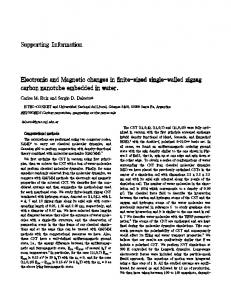
Supplementary Fig. 1 Electrochemical mechanism of bulk Sb2S3. Ex-situ XRD patterns of commercial bulk Sb2S3 at different potentials for the potassium ion battery
Supplementary Fig. 2 Morphology of commercial Sb2S3 after discharge to 0.5 V. TEM image of commercial Sb2S3 after discharge to 0.5 V with the yellow circle indicating the selected area for SAED in Fig. 1a. Scale bar: 100nm
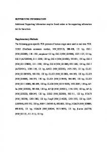
Supplementary Fig. 3 Characterizations of bulk Sb2S3 after 1st charge by electron microscope. TEM images and EDS mapping of bulk SBS after 1st charge. (a-c) Scanning TEM (STEM) images of the 1st charge product of commercial bulk Sb2S3 with inset SAED pattern of indicated area. (d) High-resolution TEM image of the bulk Sb2S3 after the 1st charge, and (eh) corresponding EDX elemental mapping of carbon, oxygen, sulphur and antimony. Scale bars in b–h are 50, 50, 5, 50, 50, 50 and 50 nm, respectively.
Supplementary Fig. 4 Morphology of commercial bulk Sb2S3. SEM images of commercial bulk Sb2S3. Scale bars: 10µm (a); 1µm (b)
Pure Sb2S3
600
Discharge Capacity Coulombic Efficiency
60
40
400
Current density (50 mA g-1)
20
200
Charge Capacity Discharge Capacity
800
Pure Sb2S3
600
600
20mA g-1
400
400
50 mA g-1 50 mA g-1
100 mA g-1 200 mA g-1
200
200
300 mA g-1 500 mA g-1
0
0 0
20
40
60
80
Cycle (n)
800
Discharge Capacity (mAh g-1)
80
800
1000
1000
Charge Capacity (mAh g-1)
b
100
Coulombic Efficiency (%)
Discharge Capacity (mAh g-1)
a1000
1 A g-1
0
0 0
10
20
30
40
Cycle (n)
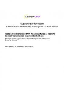
Supplementary Fig. 5 Electrochemical performance of bulk SBS. Cycling performance (a) and rate performance (b) of commercial bulk SBS.
Supplementary Fig. 6 SEM images of exfoliated SBS. (a-c) SEM images of SBS exfoliated in ethanol from different sections of bottle (a: bottom; b: middle; c: top). (d-f) SEM images of SBS exfoliated in water in different sections (d: bottom; e: middle; f: top). Scale bars in (a-f) are all the same, 1µm.
Supplementary Fig. 7 Morphology of exfoliated SBS in different solution. TEM images of layered SBS exfoliated from water (a-c), mixed solution of water and ethanol (d-f), and ethanol (g-i). Scale bars: 200 nm (a), 200 nm (b), 100nm (c), 100nm (d), 200 nm (e), 200 nm (f), 200 nm (g), 200 nm (h), 500 nm (i)
Supplementary Fig. 8 Characterization of SBS exfoliated in water. (a) XRD patterns of Sb2S3 in exfoliated in water and collected from different positions. (b) AFM images of Sb2S3 NS-3-W and cross-sectional height profiles with different layers of SBS. (c) TEM image of SBS nanosheets (NS-3-W) exfoliated in water. (d-g) Scanning TEM (STEM) images with EDX elemental mapping of sulphur, carbon, oxygen, and antimony. Scale bars: 50 nm (c); 50nm (dg)
Supplementary Fig. 9 Characterization of exfoliated SBS in ethanol. (a) XRD patterns of Sb2S3 exfoliated in ethanol and collected from different positions. (b) Raman spectra of commercial SBS, SBS NS-1-E, SBS NS-2-E, and SBS NS-3-E. (c) TEM image of SBS/C composite and the indicated carbon sheets and SBS particles. (d-f) Scanning TEM (STEM) images with EDX elemental mapping of sulphur, carbon, and antimony. Scale bars: 2 µm (c-f)
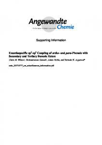
Supplementary Fig. 10 DFT calculation of diffusion energy barrier of water and ethanol in SBS. (a) Sb2S3 crystal cell model. (b) Sb2S3 (010) surface supercell model with five atomic layer thickness and 20 Å vacuum space. The relaxed initial and final states of H2O (c) and CH3CH2OH (d) diffusion from the surface of SBS (010) into the position between the second and the third layer of an Sb2S3 (110) slab along the [010] direction.
Intensity (a.u.)
SBS/C (E/W=1:1) SBS/C (E/W=2:1) SBS/C (E/W=6:1) SBS/C (E/W=8:1) SBS/C (E/W=16:1) SBS/C (E/W=32:1)
300
600
900
1200
1500
1800
-1
Raman Shift (cm )
Supplementary Fig. 11 Raman test of as-prepared SBS/C composites via one-step shear exfoliation. Raman spectrum of SBS/C composite exfoliated in different solvents.
SBS/C (E/W=2:1)
Intensity (a.u.)
Sb3d
3d5/2
3d3/2 Sb2S3
544
542
540
Sb2S3
538
536
534
532
530
b
Sb3d
Intensity (a.u.)
a
528
526
524
SBS/C (E)
3d5/2
3d3/2
Sb2S3
Sb2S3
544
542
540
Binding Energy (eV)
538
536
534
532
530
528
526
524
Binding Energy (eV)
c
d Sb3d
SBS (W)
C1s
Intensity (a.u.)
3d5/2 (Sb2S3) 3d3/2 (Sb2O3)
3d5/2 (Sb2O3)
SBS (W)
Intensity (a.u.)
3d3/2 (Sb2S3)
Sb: 56.5% S: 28% C: 9.3% O: 6.2% 544
542
540
538
536
534
532
530
Binding Energy (eV)
528
526
524
290
288
286
284
282
280
Binding Energy (eV)
Supplementary Fig. 12 Surface chemistry of SBS/C (E/W=2:1), SBS/C (E) and SBS (W). XPS analysis of Sb 3d and C 1s peaks. Sb 3d peaks of (a) SBS/C (E/W = 2:1), (b) SBS/C (E), and (c) SBS/C (W); XPS analysis of C 1s peaks of (d) SBS/C (W).
Supplementary Fig. 13 Morphology of as-prepared layered SBS/C (E/W=2:1) composite. (a-d) TEM images of SBS/C composite. (e) Typical AFM images with cross-sectional height profiles of SBS nanosheets. Scale bars: 200 nm (a); 100 nm (b); 200 nm (c); 100 nm (d)
Supplementary Fig. 14 Visual inspection of the exfoliated SBS. Color variation due to the different size and thickness of Sb2S3 for samples collected at different positions for one solution, water on the left and ethanol on the right.
0.04
0.65V
0.02
0.02
Current (mA)
b
0.63V
0.04
1.0V
1.1V
0.00
0.00
Current (mA)
a
0.78V
-0.02 0.45V
-0.04 -0.06 -0.08 -0.10 0.0
0.5
1st 2nd 3rd
-0.08
NS-3-W Sb2S3
0.31V
-0.04 -0.06
1st 2nd 3rd
0.16V
0.78V
-0.02
-0.10
1.0
1.5
2.0
Pure Sb2S3
0.26V
-0.12 0.0
0.5
+
Voltage (V vs. K /K)
1.0
1.5
2.0
Voltage (V vs. K+/K)
Supplementary Fig. 15 Comparison of CV curves between SBS NS-3-W and bulk SBS. CV curves of SBS NS-3-W (a) and commercial bulk SBS (b).
2nd 20th 40th 50th
+
Potential (V versus K/K )
2.0
1.5
1.0
0.5
0.0 0
100
200
300
400
500
-1
Capacity (mAh g )
Supplementary Fig. 16 Galvanostatic Discharge/charge profile of bulk SBS. Discharge and charge curves for selected cycles of bulk SBS at 50 mA g-1.
a
NS-3-A 0.06
b NS-3-B
NS-1-A
0.03
NS-1-B
0.03
0.00
-0.03
0.06 mV s-1 0.08 mV s-1 0.1 mV s-1 0.2 mV s-1 0.3 mV s-1
-0.06
-0.09
0.0
0.3
0.6
0.9
1.2
1.5
Current (mA)
Current (mA)
0.06
0.00
-0.03
0.06 mV s-1 0.08 mV s-1 0.1 mV s-1 0.2 mV s-1 0.3 mV s-1
-0.06
-0.09
1.8
0.0
0.3
0.6
Voltage (V)
c
0.9
1.2
1.5
1.8
Voltage (V)
0.00006
0.00005
Ip (A)
0.00004
0.00003
0.00002
NS-3-A NS-1-A NS-3-B NS-1-B
0.00001
0.00000 0.008
0.010
0.012
0.014
0.016
0.018
v0.5 ( V0.5 s-0.5)
Supplementary Fig. 17 The comparison of potassium-ion diffusion coefficient. CV curves at different scan rates of SBS electrode: (a) NS-3-W and (b) NW-1-W. (c) Peak currents versus V0.5 s-0.5 and the corresponding linear fits.
b
1000
SBS/C (E/W=4:1) 12h
800
600
-1 20mA g-1 50 mA g 100 mA g-1
Discharge Capacity (mAh g-1)
Discharge Capacity (mAh g-1)
a
20mA g-1 200 mA g-1 300 mA g-1 -1
500 mA g
400
1 A g-1
200
0
1000
SBS/C (E/W=4:1) 6h SBS/C (E/W=4:1) 12h SBS/C (E/W=4:1) 24h
800 20mA g-1
600
50 mA g-1 100 mA g-1
200 mA g-1 300 mA g-1 500 mA g-1
400 1 A g-1
200
0 5
10
15
20
Cycle (n)
25
30
35
40
5
10
15
20
25
30
35
Cycle (n)
Supplementary Fig. 18 Rate test under certain settings and with different standing times before testing. (a) Rate performance of SBS/C (E/W = 4:1) with standing time of 12 h before the test (at the current densities of 20, 50, 100, 200, 20, 300, 500 mA g-1, and 1 A g-1). (b) Rate performance of SBS/C (E/W = 4:1) electrodes with different standing times (6 h, 12 h, 24 h).
Supplementary Fig. 19 Carbon determination in various SBS/C electrodes. EDS mapping and inset spectrum showing the presence of carbon (E/W = 2:1); the inset table shows the carbon weight percentage for the composites of SBS/C (E/W = 1:1), SBS/C (E/W = 2:1), SBS/C (E/W = 6:1), SBS/C (E/W = 8:1), SBS/C (E/W = 16:1) and SBS/C (E/W = 32:1). Scale bar: 100 µm
Supplementary Fig. 20 Electrochemical properties of few-layered SBS and SBS/C electrodes fabricated via two-step exfoliation. Comparison of (a) cycling performance and (b) rate performance of SBS 4000, SBS 5000, SBS 6000, and SBS 7000 electrodes, which were exfoliated in water with different rotation rates. (c) Thickness distributions for SBS 4000, SBS 5000, SBS 6000, and SBS 7000 electrodes. Comparison of (d) cycling performance and (e) rate performance of SBS/C (E/W = 1:1), SBS/C (E/W = 4:1), and SBS/C (E/W = 16:1) electrodes, which were exfoliated via two-step exfoliation (based on the exfoliated SBS 6000 products, with different weight ratios of ethanol added for the second step exfoliation). (e) Carbon weight percentages of the SBS/C (E/W = 1:1), SBS/C (E/W = 4:1), and SBS/C (E/W = 16:1) samples. Scale bar: 25 µm (f)
Supplementary Fig. 21 Morphology of exfoliated SBS/C composites. SEM images of exfoliated SBS with the different solvents (E/W = 1:1, E/W = 2:1, E/W = 6:1, E/W = 8:1, E/W = 16:1, E/W = 32:1). Scale bars: 1 µm (a-f)
20
Percentage (%)
Thickness (nm)
ethanol to water. 40
30
0-2 .5 2.6 5.1 -5 -7.5 7.51 11- 0 13. 13. 5 6-1 16.1 6 -2 20. 0 1-2 25.1 5 30. 30 1-4 40. 0 150.1 50 -60 6180 8110 101 0 -30 301 0 -50 0
Percentage (%) 20
Percentage (%)
40
30
10 10 10
0 0 0
E/W=8:1
20
Thickness (nm)
40
30
10 10 10
0 0 0
0-2 .5 2.65.1- 5 7. 7.5 5 -1 11- 0 13.5 13.6 -1 16. 6 1-2 20.1 0 -2 25.1 5 30.1 30 -4 40.1 0 50. 50 1-6 0 6180 81100 101 -3 301 00 -50 0
Percentage (%) 20
Percentage (%)
40
0-2 .5 2.6 -5 5.1 -7.5 7.5 -1 11- 0 13 13. .5 6-1 16. 6 1-2 0 20.1 25. 25 1-3 0 30. 140.1 40 50. 50 1-6 0 6180 81100 101 -3 301 00 -50 0
E/W=1:1
0-2 .5 2.65 5.17.5 7.51 11- 0 13 13. .5 6-1 16.1 6 -2 20.1 0 -2 25.1 5 -3 30.1 0 40. 40 150.1 50 -60 6180 811 101 00 -30 301 0 -50 0
Percentage (%) 30
0-2 .5 2.6 -5 5.17.5 7.51 11- 0 13 13.6 .5 16.1 16 20. 20 1-2 25.1 5 -30 30.1 40. -40 150.1 50 -60 6180 811 101 00 -30 301 0 -50 0
0-2 .5 2.6 -5 5.1 -7.5 7.5 -1 11- 0 13 13. .5 6-1 16. 6 1-2 0 20.1 25. 25 1-3 0 30.1 40.1 40 50. 50 1-6 0 6180 81100 101 -30 301 0 -50 0
40
E/W=2:1 40
30
E/W=6:1
20
E/W=16:1 30
E/W=32:1
20
Thickness (nm)
Supplementary Fig. 22 The statistical thickness distributions of as-prepared SBS electrodes. The exfoliated products in different exfoliation solvents with different ratios of
10
30
8
25
6
20
4 15 2
Average Thickness (nm)
35
10 0
SBS Electrodes
1 E/W =3 2:
6:1 E/ W =1
E/ W =8 :1
E/ W =6: 1
E/ W =2 :1
5 E/ W =1 :1
Diffusion time Percentage (t / t(E/W=1:1)*100)
12
Supplementary Fig. 23 Comparison of K ion diffusion times for SBS/C electrodes. K ion diffusion time and the average thickness of different layered SBS electrodes (SBS/C (E/W = 1:1), SBS/C (E/W = 2:1), SBS/C (E/W = 6:1), SBS/C (E/W = 8:1), SBS/C (E/W = 16:1), SBS/C (E/W = 32:1)).
800
600
80
60
400
Current density: 1 A g-1
40
200
Coulombic Efficiency (%)
Discharge Capacity (mAh g-1)
100
20
0 200
400
600
800
0 1000
Cycle (n)
Supplementary Fig. 24 Cycling stability of SBS/C (E/W=2:1) electrode. Long-term cycling performance of SBS/C (E/W = 2:1) electrode at the current density of 1A g-1
Supplementary Fig. 25 Mixing head of exfoliation machine. Bottom view (left) and side view (right) of mixing head with indicated rotor and stator.
Supplementary Tables Supplementary Table 1. XPS analysis of electrode surface after 50th charge Samples
Content after fitting S (total)
S (-SO2-)
S (S2-)
S (S0)
S (S0)/S (S2-)
SBS/C (E)
1
33%
57.76%
9.24%
16.5%
SBS (bulk)
1
45%
50.44%
4.56%
9.04 %
Supplementary Notes Supplementary Note 1 | In order to understand the difference between water and ethanol in the ability to exfoliate Sb2S3, an Sb2S3 (010) surface model with a thickness of five atomic layers were firstly constructed based on the relaxed Sb2S3 crystal cell model (Supplementary Fig. 10a-b). The bottom two layers of atoms were fixed, and the vacuum space for the G surface was set at 20 Å to avoid coupling between the adjacent layers. Then, the adsorption and diffusion behaviour of single water or ethanol molecules on the Sb2S3 (010) surface were investigated. The adsorption energies of a single water or ethanol molecule on the Sb2S3 (010) surface were calculated by Supplementary Equations (1) and (2), respectively. Eads [Sb2S3 (010) + H2O] = Etot [Sb2S3 (010) + H2O] - Etot [Sb2S3(010)] - Etot (H2O) (1) Eads [Sb2S3 (010) + C2H6O] = Etot [Sb2S3 (010) + C2H6O] - Etot [Sb2S3(010)] - Etot (C2H6O) (2) where Etot [Sb2S3(010) + H2O] and Etot [Sb2S3(010) + C2H6O] refer to the total energies of the Sb2S3(010) surface with single water or ethanol molecule adsorption, respectively. Etot [Sb2S3 (010)] refers to the total energy of clear Sb2S3 (010) surface. Etot (H2O) and Etot (C2H6O) refer to the total energy of a single water or ethanol molecule, respectively. The calculated results (presented in Fig. 2e) indicate that water tends to be more easily adsorbed on the (010) surface of Sb2S3 than ethanol. Then, the diffusion energy barriers of water and ethanol molecules were further calculated by adopting the linear synchronous transit/quadratic synchronous transit (LST/QST) tools. The relaxed adsorption models of a single water or ethanol molecule on the Sb2S3 (010) surface (see the left-hand models of Supplementary Fig. 10c-d) were set as the initial state of the diffusion reaction, and the relaxed insertion models of a single water or ethanol molecule moving into the position between the second and the third layers of Sb2S3 (010) slabs (see the right-hand models of Figure S8c-d) were set as the final state of the diffusion reaction. The calculated diffusion energy barrier for insertion of a water molecule into Sb2S3 (010) slabs (1.2 6eV) is smaller than that of ethanol (2.2 9eV), suggesting that the path along the [010] direction is more accessible for water diffusion than ethanol diffusion.
Supplementary Note 2 | The quantitative sulfur analysis by XPS (Supplementary Table 1) was performed using the relative sensitivity factor method1. The atomic concentration ratio of S0 to S2- could be obtained according to Equation (1), as shown below: nS0/nS2- =( IS0/SS0) / ( IS2-/SS2-)
(1)
where n is the number of atoms per cm3, I is the peak area, and S the sensitivity factor. After fitting the S 2p peaks for the SBS/C and SBS electrodes, each state of sulphur content could be estimated and the ratio of elemental S0 to S2- on the electrode surface after the 50th charge could be calculated as 16.5% and 9.04% for SBS/C (E) and SBS (bulk), respectively. Supplementary Note 3 | From supplementary Fig. 17, the potassium-ion diffusion coefficient (DK+) can be calculated based on the Randles-Sevcik equation: ip = 0.4463nF
/
AC√
Where ip represents peak current, n is the number of electrons, F is the Faraday constant, R is the gas constant, T is the temperature, A is the surface area of the electrode, D is the diffusion coefficient, C stands for the concentration of potassium-ions in the electrolyte, and v is the voltage scanning rate. Supplementary Note 4 | (In order to give reasonable and accurate results for the carbon content, we pressed the composite samples on copper film, and collected more than 10 points in low magnification in order to get the average values of carbon content.); the inset TG curves of the composite (SBS/C (E/W = 2:1)) in air with a heating rate of 4 °C min-1 demonstrate the reliable results in EDS (considering that Sb2S3 is converted into Sb2O4 when heated to 800 °C in air, the carbon content in the composite (SBS/C (E:W=2:1)) is calculated to be about 4.5 wt%.
Supplementary References: 1 Moulder, J. F., Sticle, W. F., Sobol, P. E. & Bomben, K. D. Handbook of X-ray Photoelectron Spectroscopy. (Perkin-Elmer Co., Eden Prairie, MN, 1992).