SAE J1939-02 DRAFT—Serial Control and Communications Vehicle Network for
Construction and. Agricultural Applications. SAE J1939-21—Data Link Layer.
SURFACE VEHICLE RECOMMENDED PRACTICE
REV. APR2004 ®
J1939-31
Issued Revised Superseding
1994-12 2004-04 J1939-31 DEC1994
--```,``-`-`,,`,,`,`,,`---
Network Layer
Foreword This series of SAE Recommended Practices have been developed by the SAE Truck and Bus Control and Communications Network Subcommittee of the SAE Truck and Bus Electrical and Electronics Committee. The objectives of the subcommittee are to develop information reports, recommended practices, and standards concerned with the requirements design and usage of devices which transmit electronic signals and control information among vehicle components. The usage of these recommended practices is not limited to truck and bus applications, but also includes applications for construction/agricultural equipment and stationary power systems. These SAE Recommended Practices are intended as a guide toward standard practice and are subject to change to keep pace with experience and technical advances. TABLE OF CONTENTS 1. Scope ............................................................................................................................................ 3 2. References ............................................................................................................................................ 3 2.1 Applicable Publications. .......................................................................................................................... 3 2.1.1 SAE PUBLICATIONS........................................................................................................................... 3 2.1.2 IEEE PUBLICATION. ........................................................................................................................... 3 2.1.3 ISO PUBLICATIONS............................................................................................................................ 5 3. Definitions. ............................................................................................................................................ 5 3.1 Segment ............................................................................................................................................ 4 3.2 Subnetwork. ............................................................................................................................................ 4 3.3 Network Interconnection ECU (NIECU)................................................................................................. 4 3.4 Repeater ............................................................................................................................................ 4 3.5 Bridge ............................................................................................................................................ 5 3.6 Router ............................................................................................................................................ 5 3.7 Gateway ............................................................................................................................................ 5 3.8 Port ............................................................................................................................................ 5 3.9 Port_Pair ............................................................................................................................................ 5 3.10 Address Space..................................................................................................................................... 6 3.11 Transparent.......................................................................................................................................... 6
SAE Technical Standards Board Rules provide that: “This report is published by SAE to advance the state of technical and engineering sciences. The use of this report is entirely voluntary, and its applicability and suitability for any particular use, including any patent infringement arising there from, is the sole responsibility of the user.” SAE reviews each technical report at least every five years at which time it may be reaffirmed, revised, or cancelled. SAE invites your written comments and suggestions. Copyright 2004 SAE International All rights reserved. No part of this publication may be reproduced, stored in a retrieval system or transmitted, in any form or by any means, electronic, mechanical, photocopying, recording, or otherwise, without the prior written permission of SAE. TO PLACE A DOCUMENT ORDER:
SAE WEB ADDRESS:
Copyright SAE International Provided by IHS under license with SAE No reproduction or networking permitted without license from IHS
Tel: 877-606-7323 (inside USA and Canada) Tel: 724-776-4970 (outside USA) Fax: 724-776-0790 Email:
[email protected] http://www.sae.org Not for Resale
SAE J1939-31 Revised APR2004
4. Description of the Network Layer.............................................................................................................. 6 4.1 Network Interconnection Functions ....................................................................................................... 9 4.2 Network Interconnection ECU (NIECU) Types .................................................................................... 10 4.3 Network Topology ................................................................................................................................. 11 4.4 Conformance (Minimum Requirements)............................................................................................... 11 4.5 Network Interconnection ECU Performance Criteria ............................................................................ 11 4.6 Network Addressing.............................................................................................................................. 12 4.7 Off-Tractor Segment (Trailer or Implements)........................................................................................ 12 4.8 Proprietary Messages and Networks.................................................................................................... 12 4.8.1 CAN 11-BIT IDENTIFIER INTERFACING ......................................................................................... 12 4.9 SAE J1587 Interface ............................................................................................................................. 12 4.10 SAE J1922 Interface ........................................................................................................................... 13 5. Network Interconnection Software Functions ......................................................................................... 13 5.1 Forwarding .......................................................................................................................................... 13 5.2 Filtering .......................................................................................................................................... 14 5.3 Address Translation. ............................................................................................................................. 14 5.4 Foreign Message Transport.................................................................................................................. 14 5.5 Protocol Translation .............................................................................................................................. 15 5.6 Database Management......................................................................................................................... 15 5.6.1 NETWORK MESSAGE DEFINITION ................................................................................................ 16 5.6.2 MESSAGE FILTER (AND FORWARD) DATABASE (MFDB) ........................................................... 16 5.6.3 ADDRESS TRANSLATION (AT) DATABASE—TBD in future revisions of this document. .............. 19 5.6.4 MESSAGE REPACKAGING (MR) DATABASE—TBD in future revisions of this document. ........... 19 5.6.5 NETWORK INTERCONNECTION ECU PARAMETRICS (GP)—GENERAL. .................................. 19 5.6.6 NETWORK INTERCONNECTION ECU PARAMETRICS (SP)—SPECIFIC PORT_PAIR .............. 20 5.6.7 J1939 NETWORK TOPOLOGY (NT) INFORMATION...................................................................... 22 6. Network Interconnection ECU Types...................................................................................................... 22 6.1 Repeater .......................................................................................................................................... 23 6.1.1 FORWARDING .................................................................................................................................. 23 6.2 Bridge. .......................................................................................................................................... 23 6.2.1 FORWARDING. ................................................................................................................................. 23 6.2.2 FILTERING ........................................................................................................................................ 23 6.2.3 BRIDGE DATABASE MANAGEMENT .............................................................................................. 23 6.3 Router .......................................................................................................................................... 24 6.3.1 ADDRESS TRANSLATION ............................................................................................................... 24 6.3.2 MESSAGE FILTERING. ................................................................................................................... 24 6.3.3 ROUTER DATABASE MANAGEMENT............................................................................................. 24 6.4 Gateway .......................................................................................................................................... 24 6.4.1 MESSAGE REPACKAGING.............................................................................................................. 25 6.4.2 GATEWAY DATABASE MANAGEMENT. ......................................................................................... 25 7. Notes .......................................................................................................................................... 25 7.1 Marginal Indicia ..................................................................................................................................... 25
--```,``-`-`,,`,,`,`,,`---
Copyright SAE International Provided by IHS under license with SAE No reproduction or networking permitted without license from IHS
-2Not for Resale
SAE J1939-31 Revised APR2004
1.
Scope
This series of SAE Recommended Practices was developed to provide an open interconnect system for on-board electronic systems. It is the intention of these documents to allow electronic devices to communicate with each other by providing a standard architecture. This particular document describes the Network Layer which defines the requirements and services needed for the electronic devices (Network Interconnection ECUs) providing intercommunications between different segments of the SAE J1939 Vehicle Network. It also defines the various types of Network Interconnection ECUs and the functions they provide. The information in this document applies only to ECUs that are intended to provide networking services. It is not necessary for an ECU to provide any of these services in order to be compliant with the SAE J1939 protocol. 2.
References
2.1
Applicable Publications
General information regarding this series of documents is found in SAE J1939. The latest issue of SAE publications shall apply. 2.1.1
SAE PUBLICATIONS
Available from SAE, 400 Commonwealth Drive, Warrendale, PA 15096-0001. SAE J1587—Joint SAE/TMC Electronic Data Interchange Between Microcomputer Systems in HeavyDuty Vehicle Applications SAE J1922—Powertrain Control Interface for Electronic Controls Used in Medium- and Heavy-Duty Diesel On-Highway Vehicle Applications SAE J1939—Serial Control and Communications Vehicle Network—(Class C) SAE J1939-01—Serial Control and Communications Vehicle Network for Truck and Bus Applications SAE J1939-02 DRAFT—Serial Control and Communications Vehicle Network for Construction and Agricultural Applications SAE J1939-21—Data Link Layer SAE J1939-71—Application Layer SAE J1939-81—Network Management 2.1.2
IEEE PUBLICATION
Available from IEEE, 445 Hoes Lane, P.O. Box 1331, Piscataway, NJ 08855-1331. ANSI/IEEE STD.802-1D-1993—Local Area Networks: Media Access Control (MAC) Bridges
--```,``-`-`,,`,,`,`,,`---
Copyright SAE International Provided by IHS under license with SAE No reproduction or networking permitted without license from IHS
-3Not for Resale
SAE J1939-31 Revised APR2004
2.1.3
ISO PUBLICATIONS
Available from SAE, 400 Commonwealth Drive, Warrendale, PA 15096-0001. ISO 11783-Tractors, Machinery for Agriculture and Forrestry – Serial Control and Communications Network ISO 11992-Road Vehicles – Interchange of digital information on electrical connections between towing and towed vehicles ISO 15765-Road Vehicles – Diagnostics on controller area network (CAN) 3.
Definitions
See SAE J1939 for definitions that are not included in this document. See especially J1939-81 for the definition of a Controller Application, a relatively new term used within J1939 to describe a functional entity defined by the software within an ECU. This term (and its abbreviation “CA”) is used to talk about the functional entity that is sending or receiving the messages on the J1939 communications link, and is used to reduce the ambiguity that comes with using the term “ECU” when in fact a single ECU might have several separate internal functions which each use the J1939 link for different purposes. Also see Appendix for specific parameter definitions and the Suspect Parameter Numbers (SPN) associated with them. These parameters are listed in Figures 4, 6, 7, 8, and 9 where their use in PGNs and their positions in the Database are described. 3.1
Segment
This refers to the physical media of a given network and the ECUs attached to it. A single segment of a network is distinguished by all of the ECUs "seeing" the signal at the same time (i.e., there is no intermediate device between different sections of the network). Multiple segments can be connected together by Network Interconnection ECUs. 3.2
Subnetwork
This refers to the network activity (message traffic) on a specific SAE J1939 segment. Subnetworks may include: Tractor, Trailer, Implement, and Braking System. Note that subnetworks are typically separated by a bridge, router, or gateway to help minimize bus traffic on each segment. Collectively the subnetworks are the SAE J1939 Vehicle Network. 3.3
Network Interconnection ECU (NIECU)
A device that exists primarily for interconnecting networks or subnetworks. Specific implementations for “forwarding” messages include: Repeater, Bridge, Router, and Gateway.
--```,``-`-`,,`,,`,`,,`---
Copyright SAE International Provided by IHS under license with SAE No reproduction or networking permitted without license from IHS
-4Not for Resale
SAE J1939-31 Revised APR2004
3.4
Repeater
A device which regenerates the data signal to and from another segment of media. This permits the network to cover a greater distance (area), to connect more electrical loads (devices) onto the bus, or to connect to another type of media (physical layer expansion). The data rate, protocol (data link layer), and address space are the same on both sides of the repeater. A repeater usually implements message forwarding at the bit level, without storing and forwarding, and therefore does no re-ordering of messages by priority. 3.5
Bridge
--```,``-`-`,,`,,`,`,,`---
A device which stores and forwards messages between two or more network segments. This permits changes in the media and data rate between segments. The Protocol and Address Space remain the same on both sides of the bridge. Note that a bridge may selectively filter messages going across it so that the bus load is minimized on both segments. 3.6
Router
A device which allows segments with independent Address Spaces, data rates, and media to exchange messages. This permits each segment to operate with minimum bus loading yet still obtain critical messages from remote segments. The protocol remains the same across all segments. Note that the router must have look up tables to permit the translation and routing of a message with address X on segment 1 to address Y on segment 2. This also permits a vehicle system like a tractor, trailer, or implement to appear as a single device to another portion of the vehicle. 3.7
Gateway
This device permits data to be transferred between two networks with different protocols or message sets. The gateway can also provide a means to repackage parameters into new message groups when transferring messages from one segment to another, as in the case where the different “protocols” are actually different message sets (for instance one being a proprietary subnet with all proprietary messages) on J1939. 3.8
Port
The connection point from a controller to the network. Although most ECUs have only one port, a NIECU will usually have two or more ports to connect various segments together. 3.9
Port_Pair
A title that describes the two ports being discussed & the direction of data flow (from-to)
Copyright SAE International Provided by IHS under license with SAE No reproduction or networking permitted without license from IHS
-5Not for Resale
SAE J1939-31 Revised APR2004
3.10 Address Space The allowable range of Addresses on a particular Subnetwork. When using a Router for example, the Address Space is different/separate from each other for each network segment, the same address can be used for a different CA on each side of the Router. (But note that the ECUs on one segment cannot know how to directly address individual nodes on the other segment) 3.11 Transparent a device whose services may be used by other devices even when they do not know of the presence of the service provider. Thus a bridge may direct some messages to a trailer subnet while filtering others out, and change the data rate to a lower speed for the segment between the tractor and the trailer. The communicating ECUs need not know that there is a bridge present: the messages arrive at their intended destinations after being handled “transparently” by the bridge. 4.
Description of the Network Layer
--```,``-`-`,,`,,`,`,,`---
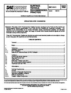
This document defines the requirements and services for electronic devices providing intercommunications between different segments of a vehicle wide SAE J1939 network. When multiple segments exist, a Network Interconnection ECU is needed to provide for the transfer of messages from one segment to another. Functions that a Network Interconnection ECU may provide include: message forwarding, message filtering, address translation of messages, and message repackaging. A Network Interconnection ECU may also support database management to permit access and configuration of the internal databases. Depending on the functions required, various types of Network Interconnection ECUs can provide these services. For example, a bridge may isolate two segments of media and the bus traffic on each, but the network is still considered "one" network in terms of address space and identifiers. See Figures 1 and 2 for typical network topologies. Port number assignments associated with particular bus segments are industry specific. All Network Layer services are optional for any given ECU, and the ability to supply any of these services is not a condition of compliance to the J1939 Recommended Practice. If an ECU is intended to supply any of the Network Layer services, this document shall be the guide for proper implementation. Section 4.4 of this document outlines the minimum requirements for ECUs providing Network Layer services other than Foreign Message Transport.
Copyright SAE International Provided by IHS under license with SAE No reproduction or networking permitted without license from IHS
-6Not for Resale
125k
--```,``-`-`,,`,,`,`,,`---
SAE J1939-31 Revised APR2004
FIGURE 1—TYPICAL SAE J1939 VEHICLE NETWORK FOR TRUCK AND BUS
Copyright SAE International Provided by IHS under license with SAE No reproduction or networking permitted without license from IHS
-7Not for Resale
SAE J1939-31 Revised APR2004
FIGURE 2—TYPICAL SAE J1939 VEHICLE NETWORK FOR AGRICULTURAL APPLICATIONS
--```,``-`-`,,`,,`,`,,`---
Copyright SAE International Provided by IHS under license with SAE No reproduction or networking permitted without license from IHS
-8Not for Resale
SAE J1939-31 Revised APR2004
Network Interconnection Functions
These are the Services provided to the network by the software in an ECU that is usually equipped with more than one Port, or network node, intended to transfer information from a port on one network segment to a port on another segment or network. These functions, in increasing order of complexity, are: 1. Forwarding message information between the segments, with minimal delay, to allow physical and electrical extension of the network. The Address Space is continuous and the Protocol must be identical on the segments so connected. The information may be transferred bit by bit (with less than bit time delay) with bit-wise message arbitration extended across the interface as long as the Data Rates are identical, or message by message (Store and Forward) with the added ability to re-order the transmission of the messages to accommodate message priority. 2. Electrical Interface Conversion, allowing such things as impedance differences between the segments. Note that the Electrical Interface Conversion is, in general, built into the physical layer of each network segment – the design of the ECU that has nodes for each of the network segments will already have compensated in any way necessary for the electrical needs (such as signal rise time) of the networks. 3. Data Rate Compensation for cases where the segments run at different rates. This may require the use of a Filtering system, as the lower-rate segment may not be able to handle the traffic of the higher rate segment. 4. Filtering the message traffic as it moves between segments, to reduce the message loading on the individual segments. 5. Foreign Message Transport can allow more efficient use of the network wiring on a vehicle by allowing the use of separate, non-interfering message sets. J1939 defines Parameter Groups for transporting, across the J1939 medium, messages whose contents are defined elsewhere. Examples of this would be the PGNs reserved for messages defined in ISO 11992, 11783, and 15765 (PGN 512, 768, 51968, 52224, 52480, 52736, 55808, 56064, 57600, 57856, etc.) This is separate from the direct transmission of parameters defined in ISO 11783 that use the standard J1939 protocol without transport requirements. 6. Address Translation, allowing for the extension of a network’s Address Space by separating it into two networks which each can have an Address Space as large as the largest single network given the Protocol adopted. 7. Protocol Translation (which may use many of the functions above) would allow data from totally different networks to be shared. An example for Vehicles would be the joining of J1587 and J1939 segments. Data extracted from messages on one network would have to be converted into different units, scaled to account for different offsets, packaged into the appropriate packet, have the correct identifiers and error detection codes added, and be sent on the other segment at the appropriate data rate.
Note that the Foreign Message Transport function differs from the rest of these Network Interconnection Functions in that it can be performed by an ECU with only one port. It does NOT extend the length or number of permissible nodes for the network since it exists on only one network segment.
Copyright SAE International Provided by IHS under license with SAE No reproduction or networking permitted without license from IHS
-9Not for Resale
--```,``-`-`,,`,,`,`,,`---
4.1
SAE J1939-31 Revised APR2004
Note that Network Interconnection ECUs may perform other functions beyond those defined in this document as provided by the supplier or as dictated by the vehicle configuration. Examples include: integrated lighting control functions or sequential trailer initialization. Network Interconnection ECUs may also be required to participate in the address claim procedure on behalf of the other ECUs on a subnetwork, particularly if the Network Interconnection ECU is serving as the main controller for a trailer, implement, or subsystem (i.e., braking). Refer to SAE J1939-01 for specific requirements of a Network Interconnection ECU to handle sequential trailer initialization, or SAE J1939-02 for specific requirements of a Network Interconnection ECU to provide the interface to the implement bus. Refer to SAE J1939-81 Network Management for specific details on the address claim procedures for Network Interconnection ECUs and other ECUs on subnetworks. Another feature that may be part of an NIECU is Database Management. This is used to access and configure the databases within a Network Interconnection ECU as defined in 5.6, Database Management. 4.2
Network Interconnection ECU (NIECU) Types
--```,``-`-`,,`,,`,`,,`---
There are particular names attached to the Functional ECU types used for Network Interconnection, which imply certain levels of complexity by describing the Functions that will be performed by ECUs of that type. 1. Repeater: this device is used to extend the length or number of nodes that can exist on a single network by allowing it to be segmented physically. No changes in Data Rate, Address Space, or Protocol are permitted for segments that are joined by a Repeater. In general, these devices are specialized hardware that transfers the data with sub-bit time delays, while the more complex devices use software for their functions. 2. Bridge: this ECU passes messages by Storing and Forwarding entire messages, and may add Filtering capabilities. It is frequently used where Data Rate changes are needed, but does no Address or Protocol Translation. 3. Router: used where Address Translation is needed, it can expand the address space of the network by allowing communication between separate address spaces. Protocol is the same on all segments. 4. Gateway: the highest complexity NIECU, the Gateway can exchange data across differing Protocols in addition to handling the other functions as needed. Looking at this as an ordered list, each NIECU can have any of the functions of the less complex ECUs included in it. Thus a Router, although capable of doing address translation, can perform message forwarding if it has a Port_Pair that use the same address space on both segments. In software terms, the NIECU Type is simply taken as that corresponding to the most complex Function that the ECU is programmed to perform. In this sense, a Router does not forward messages; the ECU that contains the “Router” function of Address Translation also contains an instance of the “Bridge” function of Message Forwarding. It may use those two software functions on separate Port_Pairs, or (if there is an overlap in the address spaces) on the same Port_Pair.
Copyright SAE International Provided by IHS under license with SAE No reproduction or networking permitted without license from IHS
- 10 Not for Resale
SAE J1939-31 Revised APR2004
4.3
Network Topology
The topology of the vehicle network must be constructed so that there is at most one communication path between any two ECUs for a given network. The OEM should therefore assure that no network loops exist on the vehicle. No special provisions are made for Network Interconnection ECUs to detect network loops or to prevent duplicate messages from being generated or replicated indefinitely. Redundant bus segments can be provided for fault tolerance, but the mechanism to detect, select, and auto reconfigure the message routing path is the responsibility of the Network Interconnection ECU supplier and is not defined within this document. 4.4
Conformance (Minimum Requirements)
A SAE J1939 Network Interconnection ECU that claims conformance to this document: 1. 2. 3. 4. 5. 6. 7. 4.5
Shall forward messages as described in this document based on NIECU type. Shall forward messages with a higher priority before those with a lower priority where applicable. Shall forward messages for a given priority in the same order as received. Shall not go bus off due to the forwarding and contention of an Address Claimed message. May support Network Interconnection ECU database management (highly recommended). Shall specify a guaranteed filtering rate and forwarding rate. Shall control transit delay (see Section 6 for NIECU recommended values) Network Interconnection ECU Performance Criteria
Three performance criteria are typically associated with a Network Interconnection ECU to determine its suitability for a given application. These criteria should be used by the system integrator to evaluate the suitability of a NIECU for use on a particular vehicle. 1.
The first is the maximum number of messages guaranteed to be forwarded per second. If this rate is exceeded due to average or peak bus loads, the Network Interconnection ECU may lose messages. 2. The second parameter is the maximum number of messages guaranteed to be filtered per second. If this rate is exceeded due to the number of entries in the database, it is possible that messages will be excessively delayed across the Network Interconnection ECU. 3. The third is the maximum transit delay. This parameter is used to determine what the worst case latency could be for a message to be transmitted by an ECU and received by another ECU on a different bus segment.
--```,``-`-`,,`,,`,`,,`---
Copyright SAE International Provided by IHS under license with SAE No reproduction or networking permitted without license from IHS
- 11 Not for Resale
SAE J1939-31 Revised APR2004
4.6
Network Addressing
The Data Link Layer provides for the potential of up to 254 unique Source Addresses on the network. (Note that the electrical loading on the bus from each ECU will restrict the total number of ECUs permitted on a given segment to a much smaller number.) If the available Address Space is insufficient for a particular application, a Router may be used to provide a separate, additional Address Space in a subnetwork. This subnetwork may contain ECUs and messages related to a specific function (Braking, Suspension, Trailer, Implement, etc.) with a main controller also serving as the router of selected messages to and from the main SAE J1939 network. 4.7
Off-Tractor Segment (Trailer or Implements)
In order to isolate and protect the tractor segment, a Network Interconnection ECU must exist between the tractor segment and any off-tractor segment. In the simplest form this would consist of a Repeater for regenerating the signal. A Bridge permits the off-tractor segment to run at a different data rate and with reduced traffic by performing message filtering. A Router permits the off-tractor segment to be developed independently, and optimized for specific functions. For those Agricultural systems following the ISO 11783 standard, a Tractor ECU (TECU) is used to separate the Tractor from the Implement Bus. See ISO 11783, Part 9 for details. See ISO 11992 for details of a possible trailer subnetwork for highway vehicles. 4.8
Proprietary Messages and Networks
The J1939 network has provisions for proprietary messages defined in the Data Link document. If Bus traffic and latency become an issue, a separate segment can be used to handle the proprietary messages. The supplier of this separate segment and its related devices must also provide any router or gateway function needed to share data with the main network. 4.8.1
CAN 11-BIT IDENTIFIER INTERFACING
All SAE J1939 compliant ECUs must support ‘the 29 bit extended frame identifier of’ CAN 2.0B. Separate subnetworks that use 11 bit standard frame identifiers (CAN 2.0A or CAN 2.0B) will require a gateway to selectively permit the transfer of data between the two segments. This device must also be responsible for any diagnostics of the subnetwork that need to be transmitted via J1939. Component suppliers and OEMs must assume responsibility for assigning unique network IDs when using 11-bit identifiers since there is no means in this document to manage addresses or Identifiers for those devices. Note that a CAN 2.0B 11-bit subnetwork could actually reside on the same two-wire segment as the J1939 main tractor network, but bus loading and reliability issues must be considered. 4.9
SAE J1587 Interface
--```,``-`-`,,`,,`,`,,`---
Devices requiring SAE J1587 for information or diagnostics must have a separate port to access that link. No provisions for defining a gateway to SAE J1587 are planned for this document.
Copyright SAE International Provided by IHS under license with SAE No reproduction or networking permitted without license from IHS
- 12 Not for Resale
SAE J1939-31 Revised APR2004
4.10 SAE J1922 Interface Since SAE J1922 was intended to be an interim standard for drivetrain control, no specific support or gateway definition will be included in this document. 5.
Network Interconnection Software Functions
--```,``-`-`,,`,,`,`,,`---
The principle functions that can be provided by a Network Interconnection ECU are: message forwarding, message filtering, address translation, Foreign Message Transport, and protocol translation. Database management can also be performed to access and configure the Network Interconnection ECU. Once operational, the Network Interconnection ECU should be essentially transparent to any ECUs on the vehicle network, in that these principal functions (excluding Database Management) are provided as services without the need for a specific request by the ECUs that take advantage of them. 5.1
Forwarding
A Network Interconnection ECU transfers individual message frames between two or more ports (one port for each network segment). The order of frames received on one port and transmitted on another shall be preserved for a given priority level. A Network Interconnection ECU other than a repeater shall forward any queued messages of a higher priority before those of a lower priority. Otherwise, all messages being forwarded to a specific port could be excessively delayed. This requirement prohibits the use of a simple First-In-First-Out (FIFO) queue for message forwarding. When a Repeater or Bridge forwards a message onto another segment, it uses the identical source address of the originator. For standard messages, this will not cause arbitration problems since the Network Interconnection ECU does not retransmit onto the segment the message originally came from, and the addresses on a given SAE J1939 network are unique. The only exception to this is when an Address Claim message is forwarded onto a segment where another ECU is simultaneously claiming the same address. In this very low probability case, the Network Interconnection ECU must have the ability to detect a bus error when transmitting this message, and should stop the automatic retransmission sequence within the CAN controller chip. Otherwise the Network Interconnection ECU will experience multiple collisions and go Bus Off, thereby preventing other messages from being forwarded until the Network Interconnection ECU is able to recover from the bus off condition. An alternative method is to have a second CAN controller which can be immediately enabled and utilized when the first one goes bus off. A Network Interconnection ECU may begin to forward messages from one segment to another before it has claimed an address if it is simply acting as a repeater or bridge, (i.e., no address translation). Note that until a Network Interconnection ECU has completed a Power Up and Self Test (POST) sequence, that each subnetwork is "isolated" from the others and ECUs will not see messages from other subnetworks until the vehicle network becomes “connected” via the Network Interconnection ECU.
Copyright SAE International Provided by IHS under license with SAE No reproduction or networking permitted without license from IHS
- 13 Not for Resale
SAE J1939-31 Revised APR2004
5.2
Filtering
This function is used to reduce message traffic on segments of the network by providing “rules” in the NIECU to allow it to pass only those messages that will be needed by receivers on each network segment. There are two basic modes of operation for the filtering process within a Network Interconnection ECU: Block List or Pass List. These modes apply to a particular Port_Pair on the NIECU. In the Block List filter mode (0), the Network Interconnection ECU will forward all messages that are not on the Block List. If there are no entries on this list, bus utilization (traffic) may be higher on each bus segment. If this is within acceptable limits, the message filtering algorithm is not needed. This is the preferred mode of operation for SAE J1939 bridges. Entries are typically made in the filter database during initial vehicle build/configuration and retained in nonvolatile memory. In the Pass List filter mode (1), the Network Interconnection ECU will default to not forwarding any messages that are not in the List. An entry must exist with a specific identifier (PGN value) for each particular message to be forwarded. This filter mode is best used for the Port_Pairs on Network Interconnection ECUs going to/from subnetworks performing a specific function (braking, suspension, etc.) or those proprietary subnetworks with few or no originated messages for the global network. Configuring this mode requires detailed prior knowledge of the ECUs and functions present on the whole network, or requires the ability for ECUs to add entries to the filter database. This method may require more memory and processing power to exist within the Network Interconnection ECU if it is to accommodate and handle a potentially large filter database. For Pass List filter mode (1), some entries within the database will need to be permanent (configured to always be present) so that the corresponding messages will always be forwarded across the whole network. Typical messages would include network management, diagnostics, and global requests. Address Translation
A Network Interconnection ECU may provide Address Translation for particular messages. This permits a single address to be used to reference a particular vehicle system (i.e., trailer or implement) without knowing the specific address of a particular function on the vehicle system (i.e., lighting). An address translation database must then exist which identifies through a look-up table the associated source or destination addresses. Note that the Network Interconnection ECU must have a valid address claimed before it can provide this address translation service. Note further that these addresses must be based upon NAME and not simply source addresses. 5.4
Foreign Message Transport
A Network Interconnection ECU may provide Foreign Message Transport when using the J1939 physical medium to transport messages defined elsewhere. This service must be implemented in each ECU that participates in the communication using the “Foreign” message set, since the message is still a J1939 message. Thus any ECU that needs to take advantage of this function must understand and abide by the J1939 CAN Identifier construction rules and the J1939 Addressing methods to assure that the Foreign messages can be transported without conflict. Only the data portion of these messages belongs to the Foreign protocol: the Identifier must conform strictly to the J1939 Recommended Practice.
Copyright SAE International Provided by IHS under license with SAE No reproduction or networking permitted without license from IHS
- 14 Not for Resale
--```,``-`-`,,`,,`,`,,`---
5.3
SAE J1939-31 Revised APR2004
5.5
Protocol Translation
A Network Interconnection ECU may provide services to extract data from another communication protocol and make it available to the J1939 network or vice-versa. The scope of this service is defined by the need for information from the non-J1939 protocol, and implementing this network function requires full knowledge of both protocols to be successful. An implementer of this function (which is normally done in a Gateway) will identify particular parameters that are available on one protocol and convert, re-scale, and broadcast that information inside the standard messages of the other protocol. This document cannot provide more specific rules for Protocol Translation. 5.6
Database Management
This optional but highly recommended service is used to provide a standard method for access and configuration of the various databases within a Network Interconnection ECU. This also includes the Network Interconnection ECU parametrics (status and statistics) and network topology. All of these functions preferably use nonvolatile memory to retain the database values through power loss. This is particularly important in order to maintain a static filter database. Provisions for a separate dynamic filter database which is cleared upon power loss to permit easy reconfiguration as ECUs are added and removed from the network is not presently defined. The filter database that exists within a Network Interconnection ECU may be configurable in several different ways: A supplier of a Network Interconnection ECU may provide it with a fixed (pre-defined) filter database. 2. A Network Interconnection ECU may be designed such that it permits the vehicle OEM to preconfigure the filter database at the time of vehicle manufacture. This requires prior knowledge of the whole vehicle network including the ECUs and messages present. This method may not adequately handle additions or changes to the vehicle network over time unless the Network Interconnection ECU can also be reconfigured during a service procedure. 3. Configuration over the network during a service procedure by a diagnostic tool using the messages defined in this section to access the filter database. 4. Network Interconnection ECU reconfiguration at any time by any ECU on the network. Note that a separate security procedure to enable the modification of the database may also have to exist. Restrictions on which ECUs may reconfigure the filter database is application and/or implementation dependent. For filter database entries created using these database management functions, a source address and/or NAME may be associated with each entry. This address/NAME represents the ECU which placed the entry, since it is also the only ECU which should remove it. Although this does not prevent ECUs from entering conflicting requests, it may prevent them from deleting entries within the filter database unexpectedly. A provision should also exist for diagnostic tools to override this address/name match requirement in order to remove entries. This document does not include details of a universal method of managing filter database entries under all conditions.
Copyright SAE International Provided by IHS under license with SAE No reproduction or networking permitted without license from IHS
- 15 Not for Resale
--```,``-`-`,,`,,`,`,,`---
1.
--```,``-`-`,,`,,`,`,,`---
SAE J1939-31 Revised APR2004
5.6.1
NETWORK MESSAGE DEFINITION
This message provides a means to access and configure the database and bridge parametrics within a Network Interconnection ECU. See Figure 3. A response is always required if a request or command is made to a specific destination (not global), even if it is an acknowledgment indicating that the particular Control function is not supported or could not be performed. Refer to SAE J1939-21 Data Link Layer for details on Acknowledgment. Note that some PGNs are multipacket, so several CAN data frames can occur as a result of a single request. An ECU should always wait for a response to its request or command, or the “no response” time-out, before sending another request or command.
Parameter Group Name: Network Definition: Used to access Network Interconnection ECU parametrics and databases Transmission Repetition Rate: Per user requirements, not recommended to exceed 5 times per second Data Length: 8 bytes, multi packet capable Data Page: 0 PDU Format: 237 PDU Specific Field: Destination Address Default Priority: 6 Parameter Group Number: 60672 (00ED00h) Data Ranges for parameters used by this group function: Byte 1: Control Byte: Control Byte: 0-6 Message Filter Database Access See Section 5.6.2 & Figure 4 64-65 Network Topology See Section 5.6.7 & Figure 9 128-133 Network Parametrics See Section 5.6.5 & Figures 6, 8 7-63, 66-127, 134-250 Reserved for future assignment by SAE 251-255 Special Indicators Defined per SAE J1939-71, Table 1 Byte 2-n: Data Fields as defined for each function, see appropriate sectIons for details Data Fields: Port_Pair, PGN_List, SA_List, Parameter Number, Parameter Value, Filter_Mode
FIGURE 3—NETWORK MESSAGE 5.6.2
MESSAGE FILTER (AND FORWARD) DATABASE (MFDB)
The functions needed to support filter database access and configuration are defined in Figure 4. The first byte in the data field is the Control Byte code which identifies the function performed. The data bytes which follow are dependent on that function. The Port_Pair is a one byte field. The upper nibble represents the “From” port, the lower nibble represents the “To” port. See Table 1 for the port numbers used for the Port_Pairs. The port number 0 (local) is used to facilitate the directing of a message by an ECU to and from a Network Interconnection ECU without requiring the ECU to know with which port of the Network Interconnection ECU it is communicating. Port “0” indicates the “local” port that received the message . Port number 15 (global) is used to facilitate the transfer of a message to all ports of a Network Interconnection ECU without requiring knowledge of how many ports the Network Interconnection ECU has. If either of the port numbers within a message (From/To) is set to global, multiple responses from the Network Interconnection ECU for each Port_Pair may be provided. The Network Interconnection ECU should be capable of configuring the filter database properly with these port values also. The Filter_Mode byte is defined in Table 2. The [PGN-list] contains zero, one, or more PGNs. If there are no PGNs in the list, the unused data bytes are set to all binary “1”s.
Copyright SAE International Provided by IHS under license with SAE No reproduction or networking permitted without license from IHS
- 16 Not for Resale
SAE J1939-31 Revised APR2004
TABLE 1—PORT NUMBERS Port Number
Definition
0
Local
1-14
Assignable
15
Global (All ports)
TABLE 2—FILTER MODE Filter Mode
Definition
0
Block specified PGNs (Default = pass all)
1
Pass specified PGNs (Default = block all)
2-250
reserved
251-255
Defined by J1939-71
PGN
Control Byte
Other Data Fields
N.MFDB_Request
60672
0
Port_Pair
N.MFDB_Response
60672
1
Port_Pair, Filter Mode, [PGN List]
N.MFDB_Add
60672
2
Port_Pair, [PGN List]
N.MFDB_Delete
60672
3
Port_Pair, [PGN List]
N.MFDB_Clear
60672
4
Port_Pair
N.MFDB_Set_Mode
60672
5
Port_Pair, Filter Mode
N.MFDB_Create_Entry
60672
6
Port_Pair, Filter Mode, [PGN List]
FIGURE 4—FUNCTIONS FOR MESSAGE FILTER DATABASE ACCESS
--```,``-`-`,,`,,`,`,,`---
Copyright SAE International Provided by IHS under license with SAE No reproduction or networking permitted without license from IHS
- 17 Not for Resale
SAE J1939-31 Revised APR2004
5.6.2.1
N.MFDB_Request
Used to request a copy of a Message Filter DataBase of the Port_Pair listed in the Data Field. 5.6.2.2
N.MFDB_Response
The response to a N.MFDB_Request which contains the filter database entries. 5.6.2.3
N.MFDB_Add
A command used to add one or more entries within the filter database. If the “To” port is set to global, appropriate entry or entries will be made in the filter data base to effect the desired action on each Port_Pair. Acknowledgment of the command is provided with the Acknowledgment Message (PGN 59392). Note that any ECU using this function must already know the Filter Mode of the particular filter database before making an entry as the Filter_Mode is not included with this command and cannot be changed without clearing and rebuilding the database for that Port_Pair. See 5.6.2.7 N.MFDB_Create_Entry for comparison. 5.6.2.4
N.MFDB_Delete
A command used to delete one or more entries within the filter database. Acknowledgment of the command is provided with the Acknowledgment Message (PGN 59392). 5.6.2.5
N.MFDB_Clear
A command used to clear one or more of the filter databases based on the Port_Pair. Acknowledgment of the command is provided with the Acknowledgment Message (PGN 59392). 5.6.2.6
N.MFDB_Set_Mode
[OBSOLETE] A command used to set the filter mode of one or more of the filter databases based on the Port_Pair (and direction). Acknowledgment of the command is provided with the Acknowledgment Message (PGN 59392). The Filter_Mode should not be changed without first clearing the filter database. This command should not be used because of the undefined result if used improperly. The J1939 committee recommends that, since the mode “should not be changed without first clearing the filter database,” the N.MFDB_Create_Entry command be used to set the mode of the new database being created for the port pair.
--```,``-`-`,,`,,`,`,,`---
Copyright SAE International Provided by IHS under license with SAE No reproduction or networking permitted without license from IHS
- 18 Not for Resale
SAE J1939-31 Revised APR2004
N.MFDB_Create_Entry
A command used to create one or more entries within the filter database. If the “To” port is set to global, multiple entries may be made in the filter database, one for each Port_Pair containing the “From” port. Acknowledgment of the command is provided with the Acknowledgment Message (PGN 59392). Note that the filter mode is included with this command to explicitly indicate whether the new entry is for block or pass. The filter mode included with the message can not change any existing filter mode for the Port_Pair. The J1939 committee recommends that the implementer of this command return an error to the requester if the N.MFDB_Create_Entry command is attempted on a non-clear database. The use of N.MFDB_Add should be sufficient, and (along with the obsolescence of the Set_Mode command) will eliminate the possibility of requesting that entries be made with differing modes in a single database record. EXAMPLE—The messages in Figure 5 would be transmitted to obtain the entries of the filter database within the Tractor-Trailer bridge (SA 032). The destination specific request is initiated from an offboard diagnostic tool (SA 248). Note that the request is only for the list of PGNs that are being filtered when going to the trailer (From port 1 to port 2). The destination specific response indicates that the only message being blocked (Filter_Mode = 0) is engine configuration (003EE3h).
Identifier PRI R P
Function
PF
DA
Data Fields SA
Control Byte
Port_Pair
N.MFDB_Request
110 0 0 237 032 248
0
12h
N.MFDB_Response
110 0 0 237 248 032
1
12h
Filter Mode
PGN
0
003EE3h
FIGURE 5—EXAMPLE OF MESSAGE FILTER DATABASE ACCESS 5.6.3
ADDRESS TRANSLATION (AT) DATABASE
TBD in future revisions of this document. 5.6.4
MESSAGE REPACKAGING (MR) DATABASE
TBD in future revisions of this document. 5.6.5
NETWORK INTERCONNECTION ECU PARAMETRICS (GP)—GENERAL
The functions required to support accessing of the Network Interconnection ECU general parametrics (status and statistics) are defined in Figure 6. A list of available parameters is defined in Figure 7. (Note that some of these parametrics may be applicable for a given NIECU, for a specific Port_Pair, or for both. These parameters can also be accessed through a Port_Pair specific parametric request. See 5.6.6). The parameter values sent within the response must be sent in the same order as the parameter numbers in the request. The J1939 Subcommittee recommends that the request always be for Parameter 0, which returns the entire list in numerical order.
Copyright SAE International Provided by IHS under license with SAE No reproduction or networking permitted without license from IHS
- 19 Not for Resale
--```,``-`-`,,`,,`,`,,`---
5.6.2.7
SAE J1939-31 Revised APR2004
Function
PGN
Control Byte
Other Data Fields
N.GP_Request
60672
128 (80h)
Parameter Numbers
N.GP_Response
60672
129 (81h)
Parameter Values
N.GP_Reset_Statistics
60672
130 (82h)
FIGURE 6—FUNCTIONS USED TO ACCESS NETWORK INTERCONNECTION ECU PARAMETERS (GENERAL) 5.6.5.1
N.GP Request
Used to request Network Interconnection ECU parametric data. Proper use is to request Parameter 0, which returns the whole list of parameters in numerical order. 5.6.5.2
N.GP Response
The response to a N.GP_Request for parameter zero contains all of the Network Interconnection ECU parametrics, in numerical order. Note that if the returned list of parameters is shorter than expected, it means that the NIECU has no knowledge of additions to the list and stopped with the last known parameter. --```,``-`-`,,`,,`,`,,`---
5.6.5.3
N.GP Reset Statistics
A command used to clear all of the statistical parameters which are resetable, noted by (*). Acknowledgment of the command is provided with the Acknowledgment Message (PGN 59392). 5.6.6
NETWORK INTERCONNECTION ECU PARAMETRICS (SP)—SPECIFIC PORT_PAIR
The functions required to support accessing of specific Parametrics (status and statistics) for a given Network Interconnection ECU Port_Pair are defined in Figure 8. A list of available parameters is defined in Figure 7. The parameter values sent within the response must be sent in the same order as the parameter numbers in the request. The J1939 Subcommittee recommends that the request always be for Parameter 0, which returns the entire list in numerical order. 5.6.6.1
N.SP Request
Used to request one or more Network Interconnection ECU parametrics. Proper use is to request Parameter 0, which returns the whole list of parameters in numerical order. 5.6.6.2
N.SP Response
The response to a N.SP_Request for parameter zero contains all of the Network Interconnection ECU parametrics, in numerical order. Note that if the returned list of parameters is shorter than expected, it means that the NIECU has no knowledge of additions to the list and stopped with the last known parameter.
Copyright SAE International Provided by IHS under license with SAE No reproduction or networking permitted without license from IHS
- 20 Not for Resale
SAE J1939-31 Revised APR2004
5.6.6.3
N.SP Reset Statistics
A command used to clear any of the statistical parameters which are resetable, noted by (*). Acknowledgment of the command is provided with the Acknowledgment Message (PGN 59392).
--```,``-`-`,,`,,`,`,,`---
Resetable
Parameter Number
Number of Bytes
0
na
Used to request all parameters in numerical order (not used in Response message)
1
2
Buffer Size (bytes)
2
2
Max. Filter Database Size (bytes)
3
2
Number of Filter Database Entries
Parameter Values
4
2
Max. Messages Received per second
5
2
Max. Messages Forwarded per second
6
2
Max. Messages Filtered per second
7
2
Max. Transit Delay Time (milliseconds)
*
8
2
Average Transit Delay Time (milliseconds)
*
9
2
# Messages lost due to Buffer Overflow
*
10
2
# Messages with Excess Transit Delay Time
*
11
2
Average Messages Received per second
*
12
2
Average Messages Forwarded per second
*
13
2
Average Messages Filtered per second
14
4
Uptime since last power on reset (seconds)
15
1
Number of Ports
16 – 253
na
Reserved for future assignment by SAE
254 – 255
na
See J1939-71 for definitions
FIGURE 7—NETWORK INTERCONNECTION ECU PARAMETRICS
Function
PGN
Control Byte
Other Data Fields
N.SP_Request
60672
131 (83h)
Port_Pair, Parameter Numbers
N.SP_Response
60672
132 (84h)
Port_Pair, Parameter Values
N.SP_Reset_Statistics
60672
133 (85h)
Port_Pair
FIGURE 8—FUNCTIONS USED TO ACCESS NETWORK INTERCONNECTION ECU PARAMETERS (PORT_PAIR SPECIFIC)
Copyright SAE International Provided by IHS under license with SAE No reproduction or networking permitted without license from IHS
- 21 Not for Resale
SAE J1939-31 Revised APR2004
5.6.7
J1939 NETWORK TOPOLOGY (NT) INFORMATION
Although Bridges are essentially transparent to other ECUs on the network, it may be necessary to know the actual topology of the network in order to properly set up the databases. Two control functions are defined in Figure 9 to obtain this information. The Port number defined in Table 1 (contained in the “to port” of the Port_Pair data byte; the “from port” is ignored) is used to help identify which source addresses are associated with each port on the Bridge. Note that if there are multiple bridges present on a given vehicle network, a bridge can only identify what port a source address is located on. A given source address may actually reside on a remote bus segment, so responses from each bridge must be compared to determine which local bus segment actually contains the given source address. A bridge may also have to perform a Request for Address Claim first in order to construct the list of source addresses associated with each port. Note that Topology Information for networks containing non-J1939 Address Spaces is not defined in this document.
Message
PGN
Control Byte
Other Data Fields
N.NT_Request
60672
64 (40h)
Port_Pair
N.NT_Response
60672
65 (41h)
Port_Pair, SA list
FIGURE 9—NETWORK TOPOLOGY (NT) 5.6.7.1
N.NT Request
Used to request the list of source addresses found on a given Network Interconnection ECU port. 5.6.7.2
N.NT Response
The response to a N.NT_Request contains the Port number and then the list of source addresses found on that port. 6.
Network Interconnection ECU Types
There are currently four Network Interconnection ECU types defined based on the functionality they provide. They are Repeater, Bridge, Router, and Gateway.
--```,``-`-`,,`,,`,`,,`---
Copyright SAE International Provided by IHS under license with SAE No reproduction or networking permitted without license from IHS
- 22 Not for Resale
SAE J1939-31 Revised APR2004
6.1
Repeater
The principle function provided by a repeater is: message forwarding between bus segments which are all running at the same data rate. This is achieved by regenerating the signal from one segment onto another at the physical layer of the network, not by storing and forwarding complete CAN data frames. Repeaters should incorporate an anti-loopback/lockout function. Bitwise arbitration is also achieved across the repeater. The repeater is essentially transparent to any ECU on the vehicle network. All messages are forwarded as there is no message filtering capability. If fault isolation is provided, the repeater has the ability to disable one or more of its transmitters if a bus fault is detected on one of the segments. No management function is defined for a repeater, so an address is not required. 6.1.1
FORWARDING
A repeater forwards all messages with only sub-bit-time delay. The maximum transit delay therefore should be less than 10% of a bit time (400 nS at 250 kbps) to permit bitwise arbitration to occur properly across the repeater, while still permitting reasonable propagation delay (cable distance). 6.2
Bridge
The principle function provided by a bridge is: message forwarding and filtering between bus segments. This is achieved by storing, filtering, and forwarding messages at the data link layer of the network. By filtering messages, the bridge can effectively reduce the amount of bus traffic present on each segment of the network. The bridge is essentially transparent to any ECU on the vehicle network. Note that there is some transit delay through the bridge. If no database management function, address management, or diagnostic capability is provided, an address is not required for the bridge. 6.2.1
FORWARDING
The maximum transit delay permitted will be application dependent. A recommended maximum value where no specific application limit exists is 50 mS. See J1939-21 for message timing information and J1939-81 for examples of Bridge delays. 6.2.2
FILTERING
A bridge may filter any, all, or none of the messages it receives. This will be dependent on the application. 6.2.3
BRIDGE DATABASE MANAGEMENT
Although not required, it is recommended that the Database Management function be supported to provide a standard access to configure the forward and filter databases.
--```,``-`-`,,`,,`,`,,`---
Copyright SAE International Provided by IHS under license with SAE No reproduction or networking permitted without license from IHS
- 23 Not for Resale
SAE J1939-31 Revised APR2004
6.3
Router
The principle operation provided by a router in addition to those provided by a bridge is: address remapping (message routing). This permits a given vehicle subsystem to appear as a single address to another portion of the vehicle, thus extending the address space of the Data Link. This can potentially simplify the development of ECUs because they do not require specific knowledge of other individual ECUs (addresses) on the vehicle subsystem. Note that Address claim messages do not cross through a router. Once operational, the router should be essentially transparent to any ECUs on the vehicle network. Note that there is some translation and forwarding delay through the router. 6.3.1
ADDRESS TRANSLATION
In addition to forward and filter functions, a Router may remap addresses from one port (bus segment) to another port (bus segment). 6.3.2
MESSAGE FILTERING
The Message Filter Database is typically configured for Pass List mode (1). All messages are then blocked unless a specific entry on the List exists to pass a message through. In addition, a lookup table must exist which provides the address translation map. 6.3.3
ROUTER DATABASE MANAGEMENT
Although not required, it is recommended that the Database Management function be supported to provide a standard access to configure the forward, filter, and address translation databases. 6.4
Gateway
The principle operations provided by a gateway in addition to those provided by a router are: message repackaging. This permits any data from another, non-J1939 network, to be placed on the J1939 Data Link as though it were being generated by the ECU that contains the Gateway function. This can simplify the design of other ECUs by giving access to data without forcing each ECU to be connected to multiple data links. Once operational, the gateway should be essentially transparent to any ECUs on the vehicle network. Note that there is some translation, repackaging, and forwarding delay through the gateway.
--```,``-`-`,,`,,`,`,,`---
Copyright SAE International Provided by IHS under license with SAE No reproduction or networking permitted without license from IHS
- 24 Not for Resale
SAE J1939-31 Revised APR2004
6.4.1
MESSAGE REPACKAGING
In addition to forward, filter, and address translation functions, a gateway may take parameters from one or more messages and repackage them into one or more “new” messages. This permits parameters to be grouped for easier transfer, reception, and interpretation by another ECU. The Message Filter Database is typically configured for Pass List mode (1). All messages are blocked unless a specific entry exists to pass a message through. In addition, a message building function must exist which contains a database for repackaging messages. 6.4.2
GATEWAY DATABASE MANAGEMENT
Although not required, it is recommended that the Database Management function be supported to provide a standard access to configure the forward, filter, address translation, and message repackaging databases. 7.
Notes
7.1
Marginal Indicia
The change bar (l) located in the left margin is for the convenience of the user in locating areas where technical revisions have been made to the previous issue of the report. An (R) symbol to the left of the document title indicates a complete revision of the report. --```,``-`-`,,`,,`,`,,`---
PREPARED BY THE SAE TRUCK AND BUS CONTROL AND COMMUNICATIONS NETWORK SUBCOMMITTEE OF THE SAE TRUCK AND BUS ELECTRICAL / ELECTRONICS COMMITTEE
Copyright SAE International Provided by IHS under license with SAE No reproduction or networking permitted without license from IHS
- 25 Not for Resale
SAE J1939-31 Revised APR2004
APPENDIX A PARAMETER DEFINITION AND SPN ASSIGNMENTS Control Byte – the indicator of the desired function of the Network message SPN = 3194 length = 1 byte Port_Pair – an ordered pair of Ports, (from – to) ; “from” port information is in the upper nibble, and is ignored if a single port is to be identified. See Table 1 and Section 5.6.7 for more information on the use of this parameter. SPN = 3214 length = 8 bits Filter_Mode – the method of filtering for a particular Port_pair: Pass (List) or Block (List) SPN = 3213 length = 1 byte PGN_List – a list of Parameter Group Numbers for filtering SPN = 3212 length = variable, a sequence of 3-byte numbers SA_List – a list of Source Addresses of ECUs that a NIECU “sees” in the segment beyond a Port SPN = 3211 length = variable, a sequence of 1-byte numbers Parameter Number – the ordinal number of a filter database parameter SPN = 3210 length = 1 byte Filter Database Parameters: Buffer Size (bytes) SPN = 3209 Parameter Number = 1length = 2 bytes Max. Filter Database Size (bytes) SPN = 3208 Parameter Number = 2length = 2 bytes Number of Filter Database Entries SPN = 3207 Parameter Number = 3length = 2 bytes Max. Messages Received per second SPN = 3206 Parameter Number = 4length = 2 bytes Max. Messages Forwarded per second SPN = 3205 Parameter Number = 5length = 2 bytes Max. Messages Filtered per second SPN = 3204 Parameter Number = 6length = 2 bytes Max. Transit Delay Time (milliseconds) SPN = 3203 Parameter Number = 7length = 2 bytes Average Transit Delay Time (milliseconds) SPN = 3202 Parameter Number = 8length = 2 bytes # Messages lost due to Buffer Overflow SPN = 3201 Parameter Number = 9length = 2 bytes # Messages with Excess Transit Delay Time SPN = 3200 Parameter Number = 10length = 2 bytes Average Messages Received per second SPN = 3199 Parameter Number = 11length = 2 bytes Average Messages Forwarded per second SPN = 3198 Parameter Number = 12length = 2 bytes Average Messages Filtered per second SPN = 3197 Parameter Number = 13length = 2 bytes Uptime since last power on reset (seconds) SPN = 3196 Parameter Number = 14length = 4 byte Number of Ports SPN = 3195 Parameter Number = 15length = 1 byte
- 26 -
--```,``-`-`,,`,,`,`,,`---
Copyright SAE International Provided by IHS under license with SAE No reproduction or networking permitted without license from IHS
Not for Resale
SAE J1939-31 Revised APR2004
Rationale This document has been modified to clarify some of the ideas that were outlined in the original. In addition, the Foreign Message Transport function has been added to explain the use of some Parameter Groups in the base J1939 document that have been assigned to be used for other protocols such as ISO 11992 and ISO 15765. The Database Management functions have also been clarified to help potential implementers produce consistent methods. Added Appendix to record the SPN number assigned to each of the parameters used in the Network message, as these will not be recorded in the Application Layer document J1939-71. This work was begun at the time of the 5-year review of the document. Relationship of SAE Standard to ISO Standard ISO 11783 was based on the work done to produce J1939. This section (J1939-31) was incorporated into that ISO document when it was first accepted. Application This document is intended to provide the framework for the creation of Network Interconnection ECUs. It should be applied to those implementations, but is not required to be a part of any application that is not specifically intended to be a NIECU. Reference Section SAE J1587—Joint SAE/TMC Electronic Data Interchange Between Microcomputer Systems in HeavyDuty Vehicle Applications SAE J1922—Powertrain Control Interface for Electronic Controls Used in Medium- and Heavy-Duty Diesel On-Highway Vehicle Applications SAE J1939—Serial Control and Communications Vehicle Network—(Class C) SAE J1939-01—Serial Control and Communications Vehicle Network for Truck and Bus Applications SAE J1939-02 DRAFT—Serial Control and Communications Vehicle Network for Construction and Agricultural Applications SAE J1939-21—Data Link Layer SAE J1939-71—Application Layer SAE J1939-81—Network Management Protocol Developed by the SAE Truck and Bus Control and Communications Network Subcommittee Sponsored by the SAE Truck and Bus Electrical / Electronics Committee
--```,``-`-`,,`,,`,`,,`---
Copyright SAE International Provided by IHS under license with SAE No reproduction or networking permitted without license from IHS
Not for Resale