Nov 24, 2008 - of the magnetic field corresponding to one magnetic flux quanta for every second plaquette of the array. The phase transitions of this model on ...
Symmetry-allowed phase transitions realized by the two-dimensional fully frustrated XY class Petter Minnhagen1 , Beom Jun Kim2 , Sebastian Bernhardsson1, and Gerardo Cristofano3 1
arXiv:0811.3840v1 [cond-mat.stat-mech] 24 Nov 2008
2
Dept. of Physics, Ume˚ a Univ., 901 87 Ume˚ a, Sweden, Dept. of Physics, Sungkyunkwan Univ., Suwon 440-746, Korea, 3 Dept. of Physics, Univ. of Naples, 80126 Naples, Italy
A 2D Fully Frustrated XY(FFXY) class of models is shown to contain a new groundstate in addition to the checkerboard groundstates of the standard 2D FFXY model. The spin configuration of this additional groundstate is obtained. Associated with this groundstate there are additional phase transitions. An order parameter accounting for these new transitions is proposed. The transitions associated with the new order parameter are suggested to be similar to a 2D liquidgas transition which implies Z2 -Ising like transitions. This suggests that the class of 2D FFXY models belongs within a U (1) ⊗ Z2 ⊗ Z2 -designation of possible transitions, which implies that there are seven different possible single and combined transitions. MC-simulations for the generalized fully frustrated XY (GFFXY) model on a square lattice are used to investigate which of these possibilities can be realized in practice: five of the seven are encountered. Four critical points are deduced from the MC-simulations, three consistent with central charge c = 3/2 and one with c = 1. The implications for the standard 2D FFXY-model are discussed in particular with respect to the long standing controversy concerning the characteristics of its phase transitions.
I.
INTRODUCTION
The two-dimensional(2D) fully frustrated XY (FFXY)-model describes a 2D Josephson junction array in a perpendicular magnetic field with the strength of the magnetic field corresponding to one magnetic flux quanta for every second plaquette of the array. The phase transitions of this model on a square lattice have been the subject of a long controversy1−8 .The emerging canonical picture is that the model has two relevant phase ordering symmetries: an angular U(1)-symmetry and a Z2 -chirality symmetry9,10,11 . As a consequence, the model has often been assumed to belong within the designation U(1) ⊗ Z2 2,3,4,12 . The controversial questions have been: Does the model undergo a single combined transition or two separate transitions and, if the latter, in which order do the transitions occur? The emerging consensus is two separate transitions: as the temperature is increased first a Kosterlitz-Thouless(KT) transition associated with the angular U(1)- symmetry and then at a slightly higher temperature a Z2 -chirality transition1,8 . The cause of the controversy can, retrospectively, be attributed to the fact that the two transitions are extremely close in temperature. We here generalize the 2D FFXY model into a a wider 2D FFXY-class of models by changing the nearest neighbor interaction in such a way as to keep all symmetries. This generalized 2D FFXY-class is shown to contain an additional groundstate. The existence of this additional grounstate leads to a phase diagram containing four sectors.13 . We here show that it has seven different phase transitions lines and four multicritical points. We use Monte Carlo simulations to establish the characters of the transitions of this phase diagram. Our simulations suggest that three of the critical points are consistent with the central charge c = 3/2 and one with c = 1. In section 2 we define the 2D FFXY-model and in sec-
tion 3 we describe the structure of the new ground state. In section 4 we propose an order parameter associated with the transition into this new groundstate. In section 5 we give the results for the various phase transitions obtained from Monte Carlo simulations and determine the character of the four multicritical points by invoking a relation between the central charge c and the bulk critical indices. In section 6 we discuss the original 2D FFXY model in view of our results. We also comment on related models not contained within the class of fully frustrated XY model discussed in the present investigation. Finally, some concluding remarks are given in section 7.
II.
GENERALIZED FULLY FRUSTRATED XY MODEL
The Hamiltonian which defines the 2D fully frustrated XY-class models on an L × L square lattice is given by H=
X
U (φij ≡ θi − θj − Aij ) ,
(1)
hiji
with φij ∈ [−π, π], where the sum is over nearest neighbor pairs. The phase angle θi for the ith site at the lattice point (xi , yi ) satisfies the periodicity θi+Lˆx = θi+Lˆy = θi . The magnetic bond angle Aij is defined as the line inteRj gral along the link from i to j, i.e. Aij ≡ (2π/Φ0 ) i A·dl with the magnetic vector potential A for the uniform magnetic field B = B0 zˆ in the z direction. With the Landau gauge taken, Aij = 2πf xi for the vertical link and Aij = 0 for the horizontal one, where the frustration parameter f measures the average number of flux quanta per plaquette. The fully frustrated case corresponds to f = 1/2 with a half flux quantum per plaquette on the average. The Boltzmann factor, which determines
2 5
2 p = 1.00 p = 1.34 p = 1.36 p = 1.50
4 3
1 2 0.5
1
(a) 0 −π
U(φ)
U(φ)
1.5
GFFXY: p = 1.00 Villain: T = 0.45
(b) −π/2
0
π/2
φ
π
−π
−π/2
0
π/2
π
0
φ
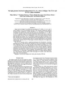
FIG. 1: Interaction potentials U (φ) in Eq. 2 at various values of p are compared in (a). The standard XY model corresponding to p = 1 is also compared with the Villain interaction potential in (b). All interactions have the same symmetry and have the identical quadratic form at small φ.
the thermodynamic properties, is given by exp(−H/T ) where T is the temperature. The interaction potential U (φ) = U (φ ± 2π) is periodic in 2π and is quadratic to lowest order in φ so that U (φ) ∼ φ2 . These conditions for the interaction potential defines the class: the members of this class are distinguished by the explicit form of the interaction potential U (φ). If the relevant symmetry class is U(1) ⊗ Z2 , then in principle three transitions are possible: separate U(1) and Z2 transitions or a merged U(1) ⊗ Z2 transition. However, the number of allowed phase transitions for the FFXY-class is much larger13. The implication is that by just changing the specific form of U (φ) within the FFXY-class one could encounter a plethora of phase transitions. In order to verify this, we choose a parametrization of U (φ) and find the phase transitions corresponding to this parametrization using Monte Carlo simulations techniques. This strategy was employed earlier in Ref.13 . The parametrization is of the form U (φ) where14,15
U (φ) =
2 φ 2 [1 − cos2p ( )] p2 2
(2)
and p = 1 corresponds to the standard FFXY since 2[1 − cos2 (φ/2))] = 1 − cos(φ). The members of the FFXY class, which belong to this parametrization, was in Ref.13 termed the Generalized Fully Frustrated XY (GFFXY) model. Figure 1a shows a sequence of interaction potentials U (φ). To sum up: The 2D FFXY class which we discuss here is obtained from the standard 2D FFXY by generalizing the interaction potential within the allowed conditions: U (φ) is a monotonously increasing function in the interval φ ∈ [0, π], U (φ) = U (φ ± 2π) is periodic in 2π and is quadratic to lowest order in φ so that U (φ) ∼ φ2 . The GFFXY model is by construction contained within this class. The Villain interaction is also contained in this class9 . In Fig. 1b the interaction potential for the standard XY model U (φ) = 1−cos(φ) is compared to the one for the Villain model at the KT-transition (T = 0.45) Pn=∞ U (φ) = −T ln{ n=−∞ exp(−(φ − 2πn)2 /2T )}.9,1 . The
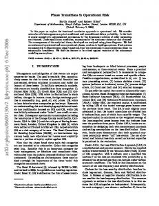
FIG. 2: Two groups of distinct groundstates of the 2D GFFXY model. (a) When p is smaller than pc (≈ 1.3479), the gauge-invariant phase difference φ = π/4 for all edges of a plaquette. (b) When p > pc , one edge has φ = π while all other three have φ = 0. The wiggled vertical lines denote the magnetic bond angles Aij = π, arrows indicate phase values, and ± represent vortex charges.
2D FFXY model with the Villain interaction has the same phase transition scenario as the usual 2D FFXY model i.e. a U(1) KT-transition followed by a Z2 transition (still extremely close together but a little less close than for the standard 2D FFXY model).1 Is this true for all models within the FFXY class? The answer is no.13 The reason is, according to us, connected to the appearance of a new groundstate.
III.
GROUNDSTATE
Let us first consider the groundstate for the standard 2D FFXY model on a square lattice: The spin configuration corresponding to the groundstate checkerboard is given in Fig. 2a.11 A square with (without) a flux quanta is denoted by + (−). The arrows give the spin directions and the thick (thin) links are the links with (without) magnetic bond angles π (0) modulo 2π. In this configuration all the links contribute the same energy U ( π4 ) to the groundstate. Thus the energy for the four links constituting an elementary square is in this configuration 4U ( π4 ). The broken symmetry of the free energy is for T = 0 directly related to the fact that in order to change + to − squares in Fig. 2a by continuously turning the spin directions from the one groundstate to the other, an increase of the energy is required by a finite amount for a number of links. This required number of links goes to infinity with the size of the system: the two groundstates are separated by an infinite energy barrier in the thermodynamic limit. The crucial point in the present context is that the groundstate shown in Fig. 2a does not remain the groundstate for all values p. As p is increased, the maximum link energy U (π) decreases and at a particular value pc > 1 the groundstate switches to the spin configuration shown in Fig. 2b. The energy for the links around a square is for this configuration given by U (π) + 3U (0).
3
+ * L2 1 X xl +yl (−1) sl , m= 2 L l=1
FIG. 3: Phase diagram of the 2D GFFXY model in the (p, T ) plane. The staggered magnetization m and the helicity modulus Y give us all four combinations, all of which are realized in the phase diagram. The horizontal dotted line at p = 1 corresponds to the standard FFXY model which has two distinct, extremely close transitions.
The critical value pc is hence given by the condition U (π) + 3U (0) = 4U ( π4 ) leading to the determination
pc =
s
ln(3/4) = 1.3479. 2 ln(cos(π/8)
(3)
The groundstate for p > pc shown in Fig. 2b has the property that an infinitesimal change of the middle spin is enough to flip between the two checkerboard patterns (switching between + and − in Fig. 2b). Thus there is no barrier between these two checkerboard patterns for p > pc . This means that the broken symmetry of the free energy associated with the two possible checkerboard patterns states is restored. However, there is a new infinite barrier between the two degenerate groundstates on opposite sides of pc : continuously turning the spins to change from the spin-configuration in Fig. 2a to the spin-configuration in Fig. 2b requires an infinite energy.
IV.
ORDER PARAMETERS
In order to characterize the phase transition properties of the 2D GFFXY model one needs to identify a set of order parameters with which all possible transitions can be characterized: The checkerboard pattern is usually associated with a Z2 chirality symmetry. For T = 0 this symmetry is reflected in the existence of two degenerate groundstates (the two checkerboards) separated by an infinite energy barrier. The corresponding order parameter is related to the staggered magnetization m defined as10
(4)
where h· · · i is the ensemble average and the vorticity for the lth elementaryPplaquette at (xl , yl ) is computed from sl ≡ (1/π) hiji∈l φij = ±1 with the sum taken anti-clockwise around the given plaquette. The corresponding broken symmetry is reflected in the following way: for any finite system the quanPL2 tity L12 l=1 (−1)xl +yl sl can with finite probability acquire any value in the range [−1, 1] allowed by the model. However, in the thermodynamic limit L = ∞ only values in either the range [−1, 0] or the range [0, 1] can be acquired. This means that the order parameter PL 2 O = h L12 l=1 (−1)xl +yl sl i in the tthermodynamiclimit only can take on the two values O = ±m. The probability for the two values are equal but they are separated by an infinite free-energy barrier. This is equivalent to saying that the order parameter O has a Z2 symmetry which is broken. In the broken symmetry region m 6= 0 whereas when the symmetry is unbroken m = 0. Figure 3 shows the phase diagram in the (T, p)-plane. As seen m 6= 0 corresponds to a finite region of this plane. For T = 0 and p = pc , the two groundstates in Fig. 2a and b are degenerate and separated by an infinite energy barrier. For T > 0 this should instead take the form of an infinite free energy barrier in the thermodynamic limit, separating values which a local order parameter can acquire. To this end one needs to identify an appropriate local order parameter. Such a possible order parameter is the defect density nk defined by
nk =
*
+ L2 4 4 X |st | , L2 t=1
(5)
where the square lattice has been divided into numerated by t where each consists of four elementary plaquettes. Here st is the sum ofP the phase difference around a four-plaquette st ≡ (1/π) hiji∈t φij which means that |st | can be 0, 1 or 2. Thus the defect density can be described in the following way: Think of the elementary plaquettes as being either black (s = 1) or white (s = −1). There are always equally many black and white squares. The defect density measures the average difference in the number of white and black squares contained in a four-plaquette. Obviously the checkerboard groundstate corresponds to a zero defect density nk = 0. However, for a finite temperature the checkerboard groundstate may contain a kink. This situation is illustrated in Fig. 4: start from a checkerboard pattern. The thick dotted line is a boundary between the two possible checkerboard patterns. The 90 degree turn of this line is associated with a four-plaquette with st = 1 L2 4 squares
4 in the pressure temperature plane: the order parameter is the density difference on the two sides of the transition line and the infinite free energy barrier only exists precisely on the transition line. The U(1)-symmetry is in 2D at most “quasi” broken because of the Mermin-Wagner Theorem16 . As a consequence the corresponding phase transitions cannot be described by a local order parameter. Instead the phase transitions can be monitored by the increase of the free energy caused by a uniform twist δ of the spin angles across the system. Expanding the free energy F (δ) for small values of δ to lowest orders gives FIG. 4: Two checkerboard states with the boundary between them (denoted as thick dotted line). A kink exists where the boundary makes a 90-degree turn, and the kink density nk is measured by Eq. (5). For the four plaquettes surrounded by thick full line, |st | = 1 whereas all other four plaquettes have even number of vortices and thus |st | = 0.
which is denoted as thick solid line surrounding four plaquettes in Fig. 4. Thus a kink corresponds to a defect with |s| = 1 according to our definition. The defect density defined here can be regarded as a generalization of the kink concept, since it does not rest on the possibility of uniquely identifying domain boundaries. Thus the defect density remains a well defined concept even when the checkerboard symmetry is completely restored and m = 0. The groundstate shown in Fig. 2b is an example of a situation when m = 0, because switching between + and - in Fig. 2b does not involve passing any energy barrier. Thus the defect density remains finite as T is lowered towards zero for any p > pc . Consequently, the groundstate in Fig. 2b corresponds to a finite defect density nk > 0. It is also obvious that the defect density is monotonously increasing with T . A phase transition associated with this order parameter is signaled by either a discontinuous or a nonanalytical behavior of nk as a function of T and p. The defect density makes a ddiscontinuousjump from zero to a finite value at pc in the limit of small temperatures and these two values are separated by an infinite energy barrier: the point (p, T ) = (pc , 0) is the starting point of a phase transition line (see Fig.3). On this phase transition line the order parameter nk can only take on two values. These two values are equally probable but are separated by an infinite free energy barrier. Thus the order parameter nk on this phase transition line possesses a Z2 symmetry which is broken. One should note that in case of nk the infinite free energy barrier between two different but equally probable values of nk only resides on well defined lines in the (p, T )-plane, whereas the infinite barrier for the chirality transition resides on an area of the (p, T )-plane (see Fig.3). Thus the phase transition associated with the defect density nk is more akin to a liquid-gas transition
F (δ) = Y
δ2 δ4 + Y4 . 2 4!
(6)
Here, Y is the helicity modulus. It is finite in the low-temperature phase and zero in the high-temperature phase.17 Y4 is the fourth order modulus and can be used to verify that the helicity modulus Y makes a discontinuous jump to zero at the transition.18 This discontinuous jump is a key characteristics of the KT-transition.19,20 V.
PHASE DIAGRAM AND PHASE TRANSITIONS
In Ref.13 the phase transitions associated with the U(1)-symmetry and the Z2 -chirality symmetry were investigated. The corresponding phase diagram is reproduced in Fig. 3. This phase diagram has four sectors corresponding to all four possible combinations of transitions for a combined symmetry U(1) ⊗ Z2 : The four sectors are characterized by the four possible combinations (Υ, m) = (0, 0), (0, 6= 0), (6= 0, 0), (6= 0, 6= 0). The dashed horizontal line at p = 1 in Fig. 3 corresponds to the usual FFXY model. In this case the phase (Υ 6= 0, m = 0) is not realized13 . In the present paper we use all the three order parameters described in the previous section together with Monte Carlo simulations in order to deduce the nature of the various phase boundaries. Fig. 5 gives a sketch of the resulting ”horizontal” phase boundary in Fig. 3. In this blown up scale one finds that it has one maximum and one minimum, as well as three multicritical points ending three distinct phase lines. The critical points are denoted by A, B, and C. A fourth multicritical point is found along the ”vertical” phase line at much higher p and lower T (see Figs.3 and 5). Let us first consider the phase boundary from T = 0 to the critical point A. Across this first section of the phase boundary the phase transition associated with the defect density nk is first order. Fig. 6a illustrates the discontinuous change in the defect density nk . The defect-density histogram along this phase line has two distinct values of equal probability which remain distinct in the large L-limit. An example is given in Fig. 6b: For a given temperature T , the lower value corresponds to the low-p phase and the
5
FIG. 5: Magnified phase diagram near pc ≈ 1.3479 (compare with Fig. 5). There are in total four multicritical points termed A, B, C, D(see text). The critical point D shown in the inset occurs at much higher p and lower T
higher to the high-p phase. As pointed out above, this is aanalogousto the density for a liquid-gas transition. Note that for T = 0.1 the p-value for the first order line is lower than pc (0). However, as T is further increased, the p-value for the first order line increases. Finally, at a critical temperature TcA the density difference vanishes with increasing system size. This is the signature of the critical point A which is hence the critical point ending the first order transition line for the defect-density. Thus the critical point A is analogous to the critical point ending the first order line for a gas-liquid transition. Fig. 6c shows the defect-density histogram close to the critical point: at the critical point the free energy barrier between the two phases is L-independent. To good approximation this means that the ratio between the maximum and minimum in the kink-density histogram should be size-independent, whereas it increases (decreases) for lower (higher) temperatures21 . This condition is fulfilled to good approximation for the T -value in Fig. 6c. At the critical point the defect-density difference ∆nk (the difference between the two maxima in Fig. 6c) should vanish with size as ∆nk ∼ L−β/ν 21 . The ∆nk size scaling is shown in Fig. 6d and is consistent with an exponent β/ν = 0.25. One can express this exponent in terms of the central charge c as β/ν = c/422,23 . The central charge c is coupled to the symmetry of the order parameter. The defect density, the staggered magnetization and the magnetization for the 2D Ising model can all aacquireprecisely two distinct values with equal probability separated by an infinite energy barrier. The broken symmetry reflected by these order parameters does hence have a Z2 -character and the phase transitions are Ising like. The central charge is c = 1/2 for 2D Ising like transitions. If the order parameter on the other hand is a 2D vector then the symmetry is U (1) (which means that the
order parameter with equal probability have the same magnitude and any direction, but that all these possibilities are separated by an infinite energy barrier) then the central charge is c = 1. Provided that our three order parameters covers all possibilities, then a phase transition can a priori be any combination of single and joint transitions involving these order parameters and is hence contained within the designation U(1) ⊗ Z2 ⊗ Z2 . These implies that the central charge can have the four values c = 1/2, 1, 3/2, and 2. Here a Z2 -transition corresponds to c = 1/2, an individual KT-transition or a combined Z2 ⊗ Z2 transition corresponds to c = 1, the two possible combined U(1) ⊗ Z2 -transitions correspond to c = 3/2, and a combined U(1) ⊗ Z2 ⊗ Z2 corresponds to c = 2. These possibilities are tested in Fig. 6d and singles out c = 1 or equivalently β/ν = 1/4. This means that of the four possible values only c = 1 is consistent with the data. As will be explained below, the helicity modulus remains non-zero in this part of the phase diagram (compare Fig.3) and consequently this suggests that the critical point A reflects a combined Z2 ⊗ Z2 defect-density and chirality transition. The defect-density transition ends at the critical point A: as T is increased the free energy barrier vanishes in the large L-limit. However, there is a second defect-density transition line for higher p-values associated with a U(1) ⊗ Z2 combined KT and defect-density transition, as illustrated in Fig. 6e and f. This transition is first order for higher p and ends at a critical point D : for a T higher than the critical point D there is no defect-density transition, just as for the case of the critical point A. Fig. 7a illustrates the chirality transition along the same phase boundary. UUp tothe critical point A (see Fig. 5) the transition is first order (see Fig. 7a). The chirality transition cannot cease at the critical point A because for a fixed T the free energy barrier between the O = ±|m| always vanishes for a large enough p. There are then two possibilities: it can continue alone as a Z2 transition or it can combine with the KT-transition into a joint U(1) ⊗ Z2 -transition. To deduce which possibility is the correct one, we calculate the size scaling of m ∼ L−β/ν and decide which of the two possible symmetry allowed values β/ν = c/4 = 1/8 or 3/8 is consistent with the data. Here we use standard size scaling and calculate m(T, p) for a fixed T for a sequence of p which crosses the phase line. As seen in Fig. 7b, a unique crossing point is to good approximation obtained for β/ν = 1/8. From this we conclude that the chirality transition continues alone from the critical point A as a Z2 -transition. However as we increase the temperature further the character of the chirality transition changes: using the same procedure we instead find that the value β/ν = 3/8 is consistent with the data (see Fig. 7c). This is consistent with a joint U(1) ⊗ Z2 KT-chirality transition. As we increase T further we come to the critical point C where the KT and chirality splits up into two separate transitions13 . At this point it is possible to instead calculate the size scaling for a fixed p. The advan-
6 1
1.2 2
1.25
1.3
1.35 p
1.4
3
0.05
0.1
0.15 0.2 nk
0.25
0.3
0
0.2
0.4 L−β/ν
L=16 20
(e) p = 30
3
2 1
(f) p = 30 0
0 0.2
0.3
0.4 nk
0.5
0.5
0.55
0.6
m
1.3477 p
1.3479
0.6 1.3481
L=16 24 32
2 1.8 1.6
(d) p = 1.346 1.6
1.4
ν = 0.77 β/ν = 0.375 Tc = 0.17
(c) T = 0.13 β/ν = 0.375
1.2 1 0.8
3
1
1.3475
2.2
1.347
4
2
1.3473
2
1.2
0.6
L=8 16 24 32
1.355
L=24 32 40
2.4
0 0
1.35 p
Lβ/ν m
40
β/ν = 0.125
1.345
2.8
∆nk (×10−2 )
6
3
0
P(nk )/Pmin (nk )
0 1.34
9
40 48 64
β/ν = 0.375 0.250 (d) T = 0.114 0.125 p = 1.3473
4
0.7
(b) T = 0.118
0.2
(c) T = 0.114, p = 1.3473 L=32
1
0.8
0.4
0 0.05 0.1 0.15 0.2 0.25 0.3 0.35 0.4 nk
1.5
0.9
0.6
(a) T = 0.1
1.45
5
L=16 24 32
Lβ/ν m
1
P(nk ) (×10−2 )
L=24 32 48 64
ϒ (×10−1 )
nk (×10−1 )
2 2
0
P(nk ) (×10−2 )
0.8
p = 1.3465
1
L=16 24 32
L=32
(b) T = 0.10
Lβ/ν m
3
(a) T = 0.10
3
1.348
1.349 p
1.35
1.351 -2
-1
0 L1/ν (T
1
2
− Tc )
FIG. 7: a) The staggered magnetization |m| at T = 0.1. b) Size scaling |m| ∼ L−β/ν for T = 0.118 (just above point A), consistent with β/ν = 1/8. c) Size scaling between point B and C, consistent with β/ν = 3/8. d) Size scaling m = L−β/ν f ((T − TcC )L1/ν ) for the critical point C: Good scaling ccollapseobtained for TcC ≈ 0.17 with ν ≈ 0.77 (from Fig. 4(d)) and β/ν = 3/8.
0.65
T p2
FIG. 6: a) First order transition of nk at T = 0.1. b) Two valued probability distribution P (nk ) at the abrupt change in a). c) P (nk ) at the critical point A. The inset shows that the ratio Pmax /Pmin is to good approximation finite and independent of L. d) Finite size scaling ,∆nk ∼ L−β/ν , is consistent with β/ν = 1/4. e) P (nk ) for a large p-value above the critical point D. The figure illustrates that Pmax /Pmin → ∞ with increasing system size. e) Helicity modulus transition at the same T and p as in e) indicating a joint first order transition.
tage is that we can use the standard size scaling form m = L−β/ν f ((T − TcC )L1/ν ). This again shows that the value β/ν = 3/8 is consistent with the data. From this we deduce that there must exist a critical point B between A and C where the chirality transition merges with the KT-transition. Are these deductions consistent with the U(1)symmetry and the helicity modulus? We argued above that the transition from T = 0 to the critical point A is associated with the Z2 ⊗ Z2 symmetry. This presumes that the U(1)-symmetry remains “quasi“ broken on both sides of the transition, or equivalently that the helicity modulus Υ is finite on both sides. This is illustrated in Fig. 8a: the helicity modulus Υ has a minimum at the phase line. However, this minimum remains non-zero in the large L-limit, as illustrated by the inset in Fig. 8a. Thus Υ makes at most a finite jump at the transition and the U(1)-symmetry remains ”quasi” broken. Next we argued that between the critical point B and C, the transition is a combined U(1) ⊗ Z2 -KT-chirality transi-
tion. This means that the helicity modulus must now vanish at the transition. This is illustrated in Fig. 8b, which shows that the Υ-minimum now vanishes in the large L-limit (compare inset in Fig. 8b). Fig. 8c shows the same construction close to the critical point C. The fact that Υ vanishes as a power law can be verified for the critical point C by instead varying T for fixed p. In these variables the critical point C obeys a standard scaling relation Υ = L−a g(((T − TcC )L1/ν ) which confirms the power law decay of Υ, as opposed to the KT-universal jump signaling the isolated U(1)-transition for the XYmodel (see Fig. 8d)13 . We also note that the obtained critical index ν ≈ 0.77 is consistent with the data for m in Fig. 7d. It is also possible to use the fourth order helicity modulus Υ4 to determine the character of the U(1)-transition18 . In Ref.13 it was found from the Υ4 data that, in the interval 1.346 ≤ p ≤ 1.35, the character of the U(1)-transition was consistent with a transition without a discontinuous jump in the helicity modulus Υ. This is consistent with a combined U(1) ⊗ Z2 -transition between the multicritical points B to C. The following picture emerges: A and D end two first order phase lines. A is associated with a Z2 ⊗ Z2 transition with central charge c = 1 and D with a U(1) ⊗ Z2 -transition with c = 3/2. B and C are both associated with U(1) ⊗ Z2 -transitions and c = 3/2 but are not end-points of first order lines.
7 6
5
(a) T = 0.1
(b) T = 0.13
4 0.3 3 2 1
0.2 L= 8 16 32 64
0 1.25
L= 8 16 32 64
0.1 0 10 1.3
1.35
100
1.4
1.45
1.25
ϒ (×10−1 )
0.2
5
0.1
4
2 1 10
1.3
1.35
1.4
100 1.45
0 1.5
p 9
10
L = 16 24 32
8
100
2 1
0.1
L= 8 16 32 64
0
3
3
0
p 6
0.2
7
(d) p = 1.346 ν = 0.77 Tc = 0.1675
(c) T = 0.1675
0 1.25
ϒ (×10−1 )
4
1.3
1.35 p
1.4
1.45
-1
-0.5
La ϒ (×10−1 )
ϒ (×10−1 )
5
6 0
L1/ν (T
0.5
1
− Tc )
FIG. 8: a) The helicity modulus, Υ, across the phase line below point A: The inset shows that the minimum of Υ remains finite with increasing size. b) Υ goes to zero for large sizes between B and C. c) Same as b) at point C. d) Size scaling relation Υ = L−a g(((T − TcC )L1/ν ) with good ccollapse for ν ≈ 0.77 (a ≈ 0.63 and Tc ≈ 0.1675 are taken from Ref.13
VI.
STANDARD 2D FFXY MODEL
The usual 2D FFXY model corresponds to the p = 1line in Fig. 3. The critical point C for the 2D FFXY class is the closest multicritical point to the actual phase transitions of the usual 2D FFXY model (compare Fig. 5). The critical point C is characterized by the critical index ν ≈ 0.77 and the central charge c = 1.5. A single Z2 transition is characterized by ν = 1 and c = 0.5. All the earlier papers, in which it was putatively concluded that the 2D FFXY model has a joint transition, the apparent value of ν was in the interval 0.77 < ν < 1 (see table 1 in Ref.1 ). In particular in Ref.5 the values of ν and c were independently determined and given by ν = 0.80(4) and c = 1.61(3). Thus the apparent multicritical point for the usual FFXY model appeared to have critical properties inconsistent with a single Z2 transition and with critical ν-values in between a single Z2 -transition and the real U(1) ⊗ Z2 multicritical point C for the 2D FFXY class. Furthermore, the closeness of the ν-values and c-values (ν ≈ 0.77 and c = 1.5 for C, respectively, ν = 0.80(4) and c = 1.61(3) obtained for the usual FFXY model in Ref.5 ) suggests that the putative multicritical point found for the 2D FFXY model is an artifact of the closeness to the real critical point C for the 2D FFXY class. The present consensus is that the 2D FFXY model undergoes two separate transition, a KT transition at TKT followed by a Z2 -transition at TZ2 with TKT < TZ2 .1 In particular Korshunov in Ref.8 has given a general argument which purportedly states that TKT < TZ2 should be
true not only for the 2D FFXY model, but also for the 2D FFXY class studied in the present work, provided that the interaction is such that its groundstate is the broken symmetry checkerboard state. This is in contradiction with the existence of the multicritical point C at p < pc (compare Fig.5) which does correspond to an interaction potential with a checkerboard groundstate. We suggest that the reason for this fallacy of the argument is connected to the closeness to the (m,Y )=(0,6=0)-phase. The most striking feature of the phase transition for 2D FFXY model is the closeness between TKT and TZ2 . The phase diagram in Fig. 5 gives a scenario for which this feature becomes less surprising: The point is that the chirality transition and the KT-transition merge and cross as a function of p for the 2D GFFXY model. It then becomes more natural that, for some values of p, the transitions can be extremely close. The value p = 1, which corresponds to the usual FFXY model happens to be such a value. There are many other U(1) ⊗ Z2 -models related to the 2D FFXY model1 . Although, our results only pertain to the 2D FFXY-class defined in this paper, we note that, to our knowledge, none of the phase diagrams for related models contain a crossing of the KT and an Ising-like transition. In a vast majority, the KT-transition is always at lower temperature than the Ising-like transition or possibly merged. However, in the model in Ref.24 the situation is reversed with the Ising-like transition below or merging with the KT-transition. Also in this case a crossing is lacking. Because there is no crossing it is notoriously difficult assert whether a merging takes place or whether the two transitions are only extremely close.1 For example the Ising-XY model was in Refs4,2,12 found to contain such a line of merged transitions. However, more careful MC simulations in fact suggest that the transitions are extremely close but never merge along this line.1 The point to note is that for our 2D GFFXY-model the transitions cross from which directly follows that a real merging exists in this case. We believe that this crossing is intimately related to the appearance of the additional groundstate.
VII.
FINAL REMARKS
To sum up, we have found that the description of the phase diagram for the 2D FFXY-class of models requires at least three distinct order parameters consistent with the proposed designation U(1) ⊗ Z2 ⊗ Z2 : In addition to the usual KT U(1) transition and the chirality Z2 transition, there is also a defect-density transition with Ising like Z2 -character. Within our simple parametrization of the interaction U (φ), we have found that all combinations of transitions can be realized except two: the single Z2 -defect transition and the fully combined U(1) ⊗ Z2 ⊗ Z2 -transition. All the others are realized, i.e. the single Z2 -chirality transition, the single U(1)-KT transition, the combined Z2 -defect and Z2 -chirality tran-
8 sition, the combined Z2 -chirality and U(1)-KT, and the combined Z2 -defect and the U(1)-KT transition. Since the GFFXY-model is a subclass of the 2D FFXY-class this means that at least five of the symmetry allowed transitions can be realized. What about the remaining two? Here we speculate that a single Z2 -density transition will hardly be realized because it couples too strongly to the other transitions. However, one might imagine that there exists a potential U (φ) for which the two nearby critical points A and B are merged. This critical point would then correspond to a merged U(1) ⊗ Z2 ⊗ Z2 -transition with central charge c = 2. We also note that Cristofano et al in Ref.25 , argued
1
2
3
4
5
6 7
8 9 10 11 12
13
14
For a recent review see, M. Hasenbusch, A. Pelissetto, and E. Vicari, J.Stat.Mech. Theor. Exp. , P12002 (2005). E.Granato, J. Kosterlitz, J. Lee, and M. Nightingale, Phys. Rev. Lett 66, 1090 (1991). J.Lee, J.M.Kosterlitz, and E. Granato, Phys. Rev.B 43, 11531 (1991). J.Lee, E. Granato, and J. Kosterlitz, Phys. Rev.B 44, 4819 (1991). E. Granato and M.P. Nightingale, Phys.Rev.B 48, 7438 (1993). P. Olsson, Phys. Rev. Lett 75, 2758 (1995). E.H. Boubcher and H.T. Diep, Phys. Rev. B 58, 5163 (1998). S. Korshunov, Phys. Rev. Lett 88, 167007 (2002). J.Villain, J. Phys. C 10, 1717 (1977). S. Teitel and C. Jayapakrash, Phys. Rev. B 27, 598 (1983). T.Halsey, J. Phys. C 18, 2437 (1985). M. Nightingale, E. Granato, and J. Kosterlitz, Phys.Rev.B 52, 7402 (1995). P. Minnhagen, B. Kim, S. Bernhardsson, and G. Cristofano, Phys. Rev. B 76, 224403 (2007). E. Domani, M. Schick, and R. Swendsen, Phys.Rev. Lett. 52, 1535 (1984).
from general symmetry considerations that the full symmetry of the FFXY-model allows for U(1)⊗Z2 ⊗Z2 . The present results for the phase diagram of the 2D GFFXY model supports this designation.
Acknowledgments
P.M. and S.B. acknowledge support from the Swedish Research Council grant 621-2002-4135. BJ.K. acknowledges the support by the KRF with grant no. KRF-2005005-J11903.
15
16
17 18
19
20
21
22
23
24
25
A. Jonsson and P. Minnhagen, Phys. Rev. Lett 73, 3576 (1994). N.D. Mermin and H. Wagner, Phys. Rev. Lett. 17, 1133 (1966). P. Minnhagen, Rev, Mod Phys 59, 1001 (1987). P. Minnhagen and B.J. Kim, Phys. Rev. B 67, 172509 (2003). D. Nelson and J. M. Kosterlitz, Phys. Rev. Lett. 39, 1201 (1977). P. Minnhagen and G.G. Warren, Phys. Rev. B 24, 6758 (1981). K. Binder and D. Heermann, Monte Carlo Simulations in Statistical Physics (Springer-Verlag, Berlin, 1992), 2nd ed. D. S. P. Di Francesco, P. Mathieu, Conformal Field Theories (Springer-Verlag, New York, 1997). Our MC-simulations give an a posteriori verification of this relation for the present model. B. Berge, H.T. Diep, A. Ghazali, and P. Lallemand, Phys. Rev. B 34, 3177 (1986). G.Cristofano, V.Marotta, P.Minnhagen, A.Naddeo, and G. Niccoli, J. Stat. Mech. Theor. Exp. 11, P11009 (2006).