TCAD Simulation for Low Power UTBB FDSOI CMOS Device Rahul Sharma
S. Baishya
Department of Electronics and Communication Engineering National Institute of Technology Silchar Silchar, India E-mail:
[email protected]
Department of Electronics and Communication Engineering National Institute of Technology Silchar Silchar, India E-mail:
[email protected]
Abstract-In this work a UTBB FDSOI model has been proposed by which leakage current is drastically reduced. Therefore it gives us freedom to scale down the device. Various comments on Sub-threshold slope (SS) and threshold voltage have been made. Effect of Buried Oxide (BOX) and Channel length variation has been described in terms of on-state current, off-state current, threshold voltage and SS. AC analysis of CMOS device has also been done by simulating the basic capacitance of proposed device. This model is highly appreciated for low power while using with multi threshold voltage. Index Terms- Ultra Thin Body and BOX (UTBB), Fully Depleted (FD), Silicon on Insulator (SOI), Simulation, Channel Length, Sub-threshold slope, Threshold Voltage.
I.
INTRODUCTION
Technologies are mainly focusing on Scaling down the device because as an outcome we get improved speed and less power consumption by the device. On the other hand it gives rise to leakage current. In this way virtue of scaling down omits. So far manufacturer has tried many things i.e. Strain engineering, changing of SiO2 by high-k dielectric and replacing polysilicon as a gate by metal. Fact is that continuous scaling down has again reduce performance, and increase leakage and variability. Now there is need to change the geometrical structure of transistor. UTBB FDSOI Technology is one of the best proposed structures [1]. The UTBB device is an attractive technology for continued CMOS scaling due to better control of the short channel effect (SCE), small threshold (VT) variability, and its compatibility with mainstream planar CMOS technology [2]-[9]. UTBB improves SCE control by further reducing electric field coupling between source and drain through the use of a thinner BOX and substrate biasing. By applying appropriate substrate biasing and substrate doping, a multi-VT device can be realized [10]. II.
SIMULATION CONDITION
The characteristics of device have been extracted from technology computer-aided design (TCAD) simulations based on an improved low-field mobility model including surface roughness and remote Coulomb scattering effects calibrated on experimental data [11].
This device has been simulated at mid-gap metal gate (ΦMG=4.7 eV), a high-k dielectric gate of 1.2 nm equivalent oxide thickness (EOT) and a Si-film of 7 nm with a doping level of 1015 cm-3 (Source/Drain). In this undoped channel concept is used in order to attain a low VT variability. The model has been made by keeping substrate doping p-type with 2x10¹⁸ atoms/cm3. Drain Induced Barrier Lowering (DIBL) is reduced due to weak inversion charge at substrate. It prevents the total control of depletion charge by gate. Sub-threshold slope concept says that it mainly depends on capacitance coupling (due to Si and due to BOX). As the thickness of BOX is reduced, consequently capacitance due to BOX will increase. Therefore finally sub-threshold slope will get increase [12]. TABLE I ELECTRICAL CHARACTERISTICS OF UTBB FDSOI NMOS AND PMOS DEVICES FOR VARIOUS BOX DEPTH AT LG =30 nm, AND VDD=0.9 V Ioff VT SS NMOS Ion (μA/μm) (pA/μm) (mV) (mV/dec) 10nm BOX
32
26
419
72.26
20nm BOX
33.8
23
421
71.16
30nm BOX
34.8
24.4
420
70.92
50nm BOX
35.7
25.8
418
70.75
70nm BOX
37
29
414
70.36
PMOS 10nm BOX
Ion (μA/μm) 34
Ioff (pA/μm) 14
VT (mV) -354
SS (mV/dec) 76
20nm BOX
33
10
-256
74.4
30nm BOX
32
8.0
-268
74.1
50nm BOX
28
4.3
-293
71.8
70nm BOX
31
5.7
-279
72
III.
DEVICE PERFORMENCE
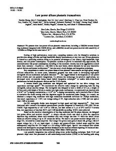
Results have been simulated for various BOXs and gate lengths. Fig1 and Fig2 explain the drain current with respect to gate voltage of NMOS at various channel lengths and boxes respectively. As we increase the magnitude of BOX, on-state current will also get increase. Therefore it can be concluded that with high thickness of box, more on-state current will be obtained. Table I describes the various parameters on variation of BOX thickness for NMOS and PMOS. Fig. 4. Drain Current versus Gate Voltage of UTBB FDSOI PMOS device for various BOXs and Lg=30nm.
Fig. 1. Drain current versus Gate voltage of UTBB FDSOI NMOS device for various Channel lengths with reference to International Technology Roadmap for Semiconductors (ITRS).
Same theory is also applicable for PMOS which is described in Fig3 and Fig4. Its characteristics lies in third quadrant because of reciprocal biasing arrangement for PMOS as compare to NMOS. Figure 5 and 6 show, the electrostatic potentials of the NMOS and PMOS devices respectively. Here, the 1D cut has been extracted from the Si-film to the substrate near the drain side. Indeed, the drain gives rise to the strongest electrical field. If backplane and well are added between BOX and substrate to perform multi VT function then also electrostatic potential will remain same [13]. Fig. 7 to 10 show, the AC simulations results of gate to source, gate to drain and gate to gate capacitance (Cgs, Cgd, and Cgg) of NMOS as well as PMOS. Note that for a MOSFET in the linear region, both source and drain regions are connected to the inversion layer, and hence Cgd ≈ Cgs ≈ 1/2Cgg, and in saturation region Cgs ≈ 2/3Cgg and Cgd ≈ 0 due to pinch-off occurring near the drain region.
Fig. 2. Drain Current versus Gate Voltage of UTBB FDSOI NMOS device for various BOXs and Lg=30nm. Fig. 5. Electrostatic Potential for NMOS UTBB FDSOI Device at Lg=30nm and BOX=10nm.
Fig. 3. Drain current versus Gate voltage of UTBB FDSOI PMOS device for various Channel lengths.
Fig. 6. Electrostatic Potential for PMOS UTBB FDSOI Device at Lg=30nm and BOX=10nm.
TABLE II ELECTRICALCHARACTERISTICS OF UTBB FDSOI NMOS AND PMOS DEVICES FOR VARIOUS CHANNEL LENGTHS AT BOX=10 nm, AND VDD=0.9 V Ioff VT SS NMOS Ion (μA/μm) (pA/μm) (mV) (mV/dec) Channel length
Fig. 7. Gate to Gate Capacitance versus Gate voltage for NMOS at 10nm BOX and Lg=30nm.
Fig. 8. Gate to Source, Gate to Drain Capacitance versus Gate voltage for NMOS at 10nm BOX and Lg=30nm.
Fig. 9.Gate to Gate Capacitance versus Gate voltage for PMOS at 10nm BOX and Lg=30nm.
Fig. 10. Gate to Drain, Gate to Source Capacitance versus Gate voltage for PMOS at 10nm BOX and Lg=30nm.
30nm
32
26
419
72.26
21nm
31.6
1.30
417
77.26
11.9nm
31.5
0.22
396
95.27
5.8nm
31.2
0.09
308
130.1
PMOS Channel length 30nm
Ion (μA/μm)
Ioff (pA/μm)
VT (mV)
SS (mV/dec)
34
14
-354
76
21nm
35
59
-217
94.8
11.9nm
37
72
-150
123.3
5.8nm
36
56
-150
257.1
Table II describes the effect on various parameters (onstate current (Ion), off-state current (Ioff), threshold voltage (VT) and sub-threshold slop) on variation of channel length (CL) with reference to ITRS. Fig 11 and 12 show the variation of Sub-threshold Slope (SS) at various channel lengths and at various BOXs for both NMOS and PMOS. It is clear from Table I and Table II that SS is decreasing on increasing the BOX thickness or channel length. In this way can take smart decision for selection of channel length and BOX thickness. SS and VT are not the only parameters to take decision for BOX thickness and channel length but Ion and Ioff are also there. This can easily be seen from Table I and Table II that for NMOS on increase in the BOX thickness or channel length, Ion and Ioff also increase. On the other hand for PMOS reciprocal of this is true. Fig 13 and Fig 14 show the threshold voltage variation on variation of BOX and channel length respectively. For NMOS threshold voltage appears almost constant while there is slight change in threshold voltage of PMOS on varying BOX/channel length of device.
Fig. 11. SS versus Channel length for NMOS and PMOS at Lg=30nm.
ACKNOWLEDGMENT The authors would like to thank TCAD LAB of NIT Silchar, India, where all the simulations are performed.
REFERENCES [1]
Fig. 12. SS versus BOX depth for NMOS and PMOS at Lg=30nm.
[2] [3] [4] [5] [6] [7] [8] [9] [10]
[11]
Fig. 13. Threshold Voltage versus Channel length for NMOS and PMOS at Lg=30nm.
[12]
[13]
Fig. 14. Threshold Voltage versus BOX for NMOS and PMOS at Lg=30nm.
IV.
CONCLUSION
A new UTBB-FDSOI device architecture with a substrate stack below the BOX has been presented. This has been proposed to optimize the channel electrostatic control. Effect of on-state current, off-state current, sub-threshold swing and threshold voltage of PMOS and NMOS have been shown on variation of BOX and Channel length individually. Split C-V measurements have been carried out on various UTBB FDSOI CMOS. The concept was validated by TCAD simulations. It has a lot to do for future work by adding back-plane (BP) and n/p-well structure between BOX and substrate. Many people are also working with new structures in order to achieve multithreshold voltage. We can extend this work for getting multithreshold voltage also.
T. Skotnick, F. Arnauld, and O. Faynot, “UTBB SOI: a wolf in sheep's clothing,” Future Fab International, vol. 42, pp. 72–79, 2012. K. Cheng, et al, Symp. VLSI Tech., p212, 2009. O. Weber, et al, IEDM, p245, 2008. C. Fenouillet-Beranger, et al, ESSDERC, p89, 2009. Y.Morita, et al, Symp. VLSI Tech., p166, 2009. J.-P. Noel, et al, ESSDERC,p137, 2009. C. Fenouillet-Beranger, et al, IEDM, p667, 2009. K. Cheng,et al, IEDM, p49 , 2009. S. Monfray, et al,IEDM, p693, 2007. Q. Liu et al,“Ultra-thin-body and BOX (UTBB) fully depleted (FD) device integration for 22nm node and beyond,” 2010 Symposium on VLSI Technology Digest of Technical Papers, pp.60-62 M.-A. Jaud, P. Scheiblin, S. Martinie, M. Casse, O. Rozeau, J. Dura,J. Mazurier, A. Toffoli, O. Thomas, F. Andrieu, and O. Weber, “TCAD simulation vs. experimental results in FDSOI technology: From advanced mobility modeling to 6T-SRAM cell characteristics prediction,” inProc. SISPAD, pp. 283–286, 2010. Olivier Thomas, Jean-Philippe Noel, Claire Fenouillet-Béranger, M.-A. Jaud, J. Dura, P. Perreau, Frédéric Boeuf, François Andrieu, D. Delprat, F. Boedt, Konstantin Bourdelle, Bich-Yen Nguyen, Andrei Vladimirescu, Amara Amara,”32nm and beyond Multi-VT Ultra-Thin Body and BOX FDSOI: From device to circuit.” ISCAS, pp. 1703-1706, 2010. J.-P. Neol, O. Thomas, C. Fenouillet-Beranger, M.-A. Jaud, P. Scheiblin and A. Amara,”A simple and Dfficient Concept for Setting up Multi-Vt Devices in Thin BOX Fully-Depleted SOI Technology,” ESSDERC, 2009.