robotic vehicle from a Cave Automatic Virtual Environment (CAVE). ...... Magda Lagoudas, the director of the Space Engineering Institute, Frank Delgado, our ...
Teleoperation from a 3D Cave Automatic Virtual Environment (CAVE) Michael A. Yager1, Amanda D. Collins1, Agustin Maqui1, David Roden2, David Taylor1, Ernest Everett3, James Reeves3, Jason York1, John Cassidy4, Stephen Glenn5, Tamás Kalmár-Nagy6 Texas A&M University, College Station, TX, 77840
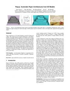
Teleoperation will become increasingly more common as a means for exploring space and for search & rescue in dangerous environments. The Space Engineering Institute (SEI) Teleoperation Team is developing a prototype system that allows for the teleoperation of a robotic vehicle from a Cave Automatic Virtual Environment (CAVE). The CAVE is an immersive two-screen virtual cockpit viewable with 3D glasses. The system will be evaluated for its ability to enhance situational awareness for the teleoperator. A full plan for the teleoperation of a Ford F-150 is presented. Preliminary results of the vehicle sub-systems are discussed. The control system design for an iRobot is also presented.
I.
Introduction
I
n the near future, teleoperable rovers will be exploring the moon and performing search & rescue work in hazardous environments. On the moon, rovers will spend only a small fraction of their time under direct control by astronauts. The majority of their time will be spent under the command of an Earth-based teleoperator. NASA has already performed extensive teleoperation exercises on the SCOUT rover testbed. Additionally, they have tested a five-screen virtual cockpit using a combination of live video with a synthetic environment. The synthetic environment, which is a 3D model created for the robotic vehicle’s operating environment, offers increased situational awareness over live video alone. Waypoints, markers, danger-zones, and objectives can all be displayed easily directly on the virtual terrain. Customizable head-up displays (HUD) can present relevant information in a way best suited for different teleoperators and different situations. An additional advantage is the savings on data transmission—situational awareness can be increased without having to transmit large amounts of video. Complex lunar missions involving robotic interactions with structures and payloads will require a high-level of situational awareness for teleoperators. Search & rescue teams will also need a data-rich, immersive environment to properly teleoperate their robotic vehicles in dangerous situations. The Teleoperation Team at Texas A&M University’s Space Engineering Institute (SEI) is developing a prototype teleoperation system to test a Cave Automatic Virtual Environment (CAVE) with stereoscopic (3D) capability. The CAVE functions as a remote cockpit for the vehicle, providing 3D viewing of a geo-referenced model of the operating environment. Both an iRobot Create and a modified Ford F-150 truck will serve as teleoperable vehicles. This document presents the setup and operation of the
1
Undergraduate Researcher, Department of Aerospace Engineering, 3380 University Drive East Suite 102, College Station, TX 77845, Student. 2 Undergraduate Researcher, Department of Computer Science, 3380 University Drive East Suite 102, College Station, TX 77845, Student. 3 Undergraduate Researcher, Department of Mechanical Engineering, 3380 University Drive East Suite 102, College Station, TX 77845, Student. 4 Undergraduate Researcher, Department of Electrical Engineering, 3380 University Drive East Suite 102, College Station, TX 77845, Student. 5 Graduate Researcher, Department of Mechanical Engineering, 3380 University Drive East Suite 102, College Station, TX 77845, AIAA Student Member 6 Assistant Professor, Department of Aerospace Engineering, 3141 TAMU College Station, TX 77843-3141, AIAA Senior Member.
1 American Institute of Aeronautics and Astronautics 092407
CAVE system, the wireless network communication system, and the vehicles. Software development, modeling, and preliminary test results are also presented.
II.
Teleoperation System
A. Overview Teleoperation systems are composed of a vehicle and base station connected through a network as shown in Figure 1. The teleoperator sends commands to the vehicle using a control device. Actuators react to these commands and change the state of the vehicle. Sensors collect data on the state of the vehicle and send the information back to the base station. This feedback is interpreted and displayed for the teleoperator.
Vehicle
Base Station Control Device
Sensors Communication Actuators
Teleoperator Feedback
Figure 1. Abstract teleoperation system A modified Ford F-150 truck provided by Texas Engineering Experiment Station (TEES) will be used as our main test vehicle, while an iRobot Create will serve as a preliminary test vehicle. The implementation of the above general teleoperation system structure for the Truck is presented in Figure 2 below. A computer on the truck will run MATLAB and C code to communicate with the sensors and actuators. The installed sensors are a GPS unit, an Inertial Measurement Unit (IMU), and a video camera. These allow the location, orientation, velocity and other details of the state of the vehicle to be recorded. Sensors GPS, IMU, Video
Truck PC
Joystick Control PC
CAVE PC 2 Simulink
LandForm software
Projector 2 CAVE PC 1
Wi-Fi
MATLAB, C
ß Commands à Sensor Data
Emitter Actuators Brake/Throttle, Steering
Glasses
LandForm software
Projector 1
Figure 2. Implementation of teleoperation system for TEES Ford F-150 truck The base station is divided into three separate computers. The first computer is running Simulink code connected to a joystick and allows the teleoperator to control the vehicle. The other two computers provide feedback to the teleoperator as part of our CAVE system, used to immerse the teleoperator in a virtual environment. The CAVE PC’s are running a software package called LandForm that displays the vehicle’s state within a three-dimensional environment based on the sensor data received from the vehicle. This environment is displayed using two stereoscopic projectors, offering a wide field of view for the teleoperator. An emitter sends a signal to a special pair of glasses that creates a sense of depth to the projected display. This allows the teleoperator to have better situational awareness while controlling the vehicle. B. CAVE In the base station, a Cave Automatic Virtual Environment (CAVE) system is utilized to provide data-rich, immersive feedback to the teleoperators. A diagram of the base station, including the screens and 3D equipment that comprises CAVE, is presented below in 2 American Institute of Aeronautics and Astronautics 092407
Figure 3. The immersive virtual reality environment will be evaluated for enhancing situational awareness of the vehicle within its surroundings. The CAVE system is located indoors, and in the case of the Truck will not have direct line of sight. High-powered wireless routers are used to enable communication with the Truck outside the building. Our CAVE is comprised of two projectors that display a continuous image across two screens. The screens are mounted at a 90-degree angle to each other to allow for a wider simulated field of view. The illusion of depth is achieved by creating two versions of the display—one for the left eye and the other for the right eye. The difference between common points in each version is the separation distance. Larger separation distance results in a point appearing closer to the viewer, while smaller separation distance makes a point appear farther away. As the two versions are alternately displayed, LCD shutter glasses prevent each eye from seeing the display version intended for the other eye. The rapid alternation of slightly different left-eye and right-eye versions of the display is interpreted by the brain as a single 3D image. BNC Connector 3-PIN mini-DIN Connector to Graphics Card
IR Sync Signal
CrystalEyes Emitter
CrystalEYES Glasses
M1 to VGA USB
CAVE PC 1 inFocus DEPTHQ Projector 1
Control Computer USB
Ethernet Cable
Joystick Wireless Signal
TROPOS Wireless Router
NVIDIA Graphics Cards Synced with Ethernet Cable
Ethernet Cable Ethernet Cable
Ethernet Cable
Hub
inFocus DEPTHQ Projector 2
M1 to VGA USB
CAVE PC 2
Figure 3. Base station system diagram, including CAVE Special hardware is required to provide stereographic 3D vision. Higher refresh rates result in more comfortable viewing. The system is set at 120 Hz, which is the highest refresh rate allowed by the desktop monitors currently in use. On each computer, LandForm produces the alternating left-eye and right-eye versions of the display. NVIDIA Quadro FX 3000G graphics cards installed in each CAVE PC generate the rapidly changing video signals based on the output of the LandForm software package. The cards also provide synchronization signals to insure that both screens display left-eye and right-eye versions in coordination with the shutter glasses. CAVE PC 1 acts as the server, providing a synchronization signal to CAVE PC 2 and to the CrystalEYES emitter. The emitter synchronizes any shutter glasses in range of its infrared (IR) signal with the server. Each pair of shutter glasses has a built-in receiver for the IR sync signal. The glasses alternately darken the left and right lenses by activating an LCD layer in the lens. The inFocus DEPTHQ projectors are designed to operate at the high refresh rates desired for stereographics. C. LandForm The 3D virtual environment displayed by the CAVE is first modeled using LandForm Gold by Rapid Imaging Software, Inc. LandForm allows the user to place 3D markers such as buildings or flags at specific GPS coordinates as well as model the terrain elevations. LandForm can then render these environment details in 3D from a viewpoint of the user’s preference, and modify the view accordingly as the coordinates, heading, or other parameters change in real-time. Transferring these parameters requires little memory and bandwidth compared to transferring video yet provides a high level of situational awareness. When visibility is obscured by environmental factors such as fog or darkness, LandForm improves the amount of visual information received because it relies on GPS data rather than video to create its image. LandForm can also improve navigation by showing synthetic details directly on the environment, such as waypoints, desired paths, vehicle speed, and compass heading. The major limitation is that the LandForm model may not include obstacles the modeler was unaware of or that appeared after the model was 3 American Institute of Aeronautics and Astronautics 092407
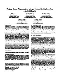
created. For this reason, the teleoperation system includes live video and the vehicles are restricted to the boundaries of the modeled terrain. A section of the parking lot outside the Spacecraft Technology Center in College Station is used as the initial testing environment for the Truck. This section has only a few obstacles including light poles in the center and some machinery along the perimeter. This environment was modeled in LandForm by finding the GPS coordinates and lengths of the corners and obstacles and referencing them within the model parameters. A preliminary model is shown below in Figure 4. LandForm displays this environment at the point of view of GPS coordinates and heading received from the Truck and sends this visual data in stereographic form to the projectors to be displayed in the CAVE in 3D. In this manner, the viewpoint of the Truck is depicted synthetically as it is teleoperated around the environment.
Figure 4. Screenshot of LandForm with bird’s eye view of STC parking lot model An important part of the LandForm software package is the Source Interface Library (SIL), which is detailed in Figure 5. SIL is a program compiled in C++ that receives vehicle sensor data from across the network and passes it to LandForm. It is a dynamic-link library (.dll) file that is loaded into the LandForm software. Once loaded, it establishes a connection to the truck computer using a User Datagram Protocol (UDP) socket. When a datagram is received from the truck computer, it determines what information is contained within the message. The data is parsed and stored into separate channels in the system memory. Each channel represents different measurements, such as longitude, latitude, or velocity. When LandForm refreshes, it makes a call to the SIL for the most recent values. These values may be altered to estimate for the difference in time from when they were recorded. LandForm displays the values of each channel on the HUD. Source Interface Library (SIL) STORE
Network
RECEIVE GPS, IMU strings via UDP Socket
PARSE Latitude, longitude, heading, etc.
REFRESH
System Memory Channel 1 Channel 2 … Channel n
ESTIMATE Adjust Values for Delay
SEND Transfer to LandForm
LandForm
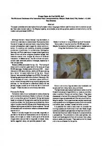
Figure 5. Data flow of Source Interface Library (SIL) D. Truck The 2004 Ford F-150 4x4 Truck provided by Texas Engineering Experiment Station (TEES), seen below in Figure 6, is a platform for testing the teleoperation of a vehicle. The Truck is significantly modified from a standard F-150. First, an Electronic Mobility Controls (EMC) system was installed onto the Truck. This control system is for individuals with disabilities and allows one to control the motion of the vehicle by using a joystick and a rotating knob on a control pad. This EMC uses two actuators to control the truck, one for steering and another for the brake and throttle. Additionally, it has two Emergency Stop (E-Stop) buttons that engage the brake and a wireless kill switch to turn off the engine. For future off-road testing, the 4x4 Truck has been equipped with a lift kit and large low pressure tires. 4 American Institute of Aeronautics and Astronautics 092407
Figure 6. 2004 Ford F-150 4x4 truck provide by TEES 1. Components The Truck subsystem is grouped into Sensors, Actuators, and the Truck PC as shown in Figure 7. The Truck PC will interface with the communication system via an Ethernet cable connected to a TROPOS 1510 MetroMesh Outdoor Wireless Router on board the Truck. Incoming control commands from the Base Station will be received by the Truck PC and passed to the actuators via the USB-1208FS Data Acquisition Unit (DAQ) and EMC system. Sensor data will also be collected by the Truck PC and passed to the Base Station via the TROPOS wireless router. Three sensors will be used. First, the use of a NovAtel – ProPak LB+ Global Positioning System (GPS), with an operational frequency of 20 Hz, will provide high-quality position measurements. Second, the Watson Ind. BA604 Inertial Measurement Unit (IMU), with a transfer rate of 9600 Kbits/s, using accelerometers, gyroscopes, and a fluxgate magnetometer will provide measurements such as acceleration and heading. Third, a Logitech QuickCam Messenger Video Camera will be attached to the Truck’s external steel frame to provide live video for testing. SENSORS
ACTUATORS SEND GPS, IMU, VIDEO DATA using UDP
Video Camera
E-STOP
GPS antenna
E
STEERING, BRAKE/THROTTLE
EMC
Analog Signal
Ethernet Cable
IMU
E-STOP
K
E
RECEIVE STEERING, BRAKE/THROTTLE COMMANDS using UDP
TROPOS
KILL SWITCH
RS-232 Serial
DAQ
Steering Voltage
Gas/Break Voltage
USB RS-232 Serial NovAtel GPS unit
USB CPU Pentium 4, 3.8 GHz 2 GB Ram
STEERING, BRAKE/THROTTLE
Digital Signal
Steering Servo
Gas/Break Servo
Figure 7. Truck system diagram 2. Code The Truck code is required to collect the sensor data and send them to the Base Station while receiving commands from the Base Station and sending them to the actuators. Currently, the code is written in MATLAB since it is relatively easy to use and can achieve all the functions necessary for the project. To receive data from the three sensors, the code first creates three serial objects as shown in Figure 8 below. For the GPS and IMU objects, the Communication Port (COM Port), Baud Rate, Data Bits, and Stop Bits are specified based on the specifications of the sensor. The Baud Rate determines how fast the data will be moving between each sensor and the computer. The Data Bits determine the number of bits used to represent one character of data. The Stop Bits determine the end of the character frame. Next, the objects are opened to establish the connection with the sensors. At this point, the code begins continuously scanning each object for any data. The data is saved to virtual memory and then sent across the wireless network. This is handled by a User Datagram Protocol (UDP) object, which requires the IP address and port number of both the local and remote computer. Another UDP object is created for receiving commands from the Control PC. This object is continuously scanned, providing the latest command data that is then parsed and passed to a serial object for the DAQ.
5 American Institute of Aeronautics and Astronautics 092407
GPS antenna
NovAtel GPS unit
READ GPS on COM1 with: RS-232 BaudRate = 115200 Serial DataBits = 8 StopBits = 1
IMU RS-232 Serial
READ IMU on COM7 with: BaudRate = 9600 DataBits = 8 StopBits = 1
WRITE DATA STRING TO MEMORY $GPRMC,221032.00,A,3038.8323694,N,096 17.7714852,W,0.343,94.4,190108,0.0,E*7C
SEND STRING data using UDP through TROPOS
WRITE DATA STRING TO MEMORY I +0.10 +0.04 -1.02 -00.6 +02.0 +01.8
SEND STRING data using UDP through TROPOS
Network
TROPOS
Video Camera
USB
READ VIDEO Camera on USB
WRITE DATA TO MEMORY Picture in .jpg format
SEND IMAGE data using UDP through TROPOS
Figure 8. Truck sensor code diagram E. Vehicle Controls To successfully teleoperate any vehicle from a remote location, a control system capable of reading the operator’s commands and sending these commands to the vehicle must be properly designed, tested, and implemented. The type of command signals sent to a teleoperated vehicle depends upon the type of vehicle being used and its function. For our application, a simple control system was designed to send the Truck commands regarding its speed, direction, and acceleration. The system incorporates velocity and GPS position feedback from the Truck. A MATLAB modeling program called Simulink was used for all system control software. The Simulink program reads the joystick input from the vehicle operator, converts this input into a compatible format, and then sends this information to the Truck PC. The basic control system model is shown below in Figure 9.
Figure 9. Overview of teleoperation control system The joystick block receives the dual axis position of the joystick and passes this information to the gain, tolerance, and rate limiter block. The gain, tolerance and rate limiter block conditions the signal and passes the signal through the E-stop control block. The E-stop control subsystem reads the emergency stop button on the joystick and when the E-stop button is depressed, interrupts the normal flow of the control system to stop the vehicle. After leaving the E-stop subsystem, the signal enters the speed control block, which contains a speed feedback system to limit the speed of the vehicle to 20 miles per hour. Finally, the UDP Pack and Send block receives the control system output command signals and converts these into a format compatible with UDP protocol before sending these commands over the wireless network to the Truck. The joystick block is a Simulink object provided by Simulink’s Virtual Reality Toolbox. This block identifies the joystick in the computer, reads its position, and outputs the joystick’s axis positions as a two dimensional vector normalized to the range of -1 to +1. The rest of the system reads the first element of the vector as the position of the joystick on the x-axis, and the second element of the vector as the joystick’s position on the y-axis. A +1 value in yaxis corresponds to maximum allowable throttle, while a -1 value in the y-axis corresponds to maximum break application. A +1 value in the x-axis tells the system to turn the vehicle the maximum steering angle of 35° right, while a -1 value in the x-axis tells the system to turn the vehicle the maximum steering angle of 35° left. In addition to the joystick’s position, the joystick block also outputs a +1 value every time a button on the joystick is held down. By using a demuliplexer to filter out the signals of the unused joystick buttons, we were able to add an emergency stop button to the joystick for the Truck operator’s emergency use. The gain, tolerance, and rate limiter block is one subsystem of the control system, and is displayed below in Figure 10. It receives the vector output of the joystick block, amplifies it, adjusts the sensitivity of the control system, and limits the rate of vehicle acceleration as shown in the diagram below. This block allowed us to tune the response of the vehicle to the joystick’s movements.
6 American Institute of Aeronautics and Astronautics 092407
Figure 10. Gain, tolerance, and rate limiter subsystem The E-stop controls subsystem, shown below in Figure 11, was designed to bring the vehicle to a stop when the joystick’s E-stop button is depressed. When it receives the E-stop button’s signal, this subsystem sends the vehicle commands to reduce its speed to zero and straighten its wheels. It accomplishes this task through use of a multiport switch. When the E-stop button is not depressed the joystick commands flow uninterrupted through the switch and pass on to the speed control subsystem. However, when the E-stop button is depressed, the multiport switch switches to allow the vector , of double data type, to pass to the speed control subsystem. The vector tells the Truck to apply the maximum breaking effort. At the button input, the demultiplexer button signal filter is placed to filter out the unused joystick button signals. This signal then flows from the demultiplexer to the sample and hold block, which outputs a value of 1 when the depressed button’s signal is sent. When the multiport switch receives the value of 1 at its control port, it switches from outputting the joystick commands to outputting the vector .
Figure 11. The E-stop control subsystem The speed control subsystem block, shown below in Figure 12, was designed to limit the speed of the vehicle to 20 mph. If the vehicle exceeds 20 mph, the speed control subsystem forces the vehicle to come to a stop and straighten its wheels. This block first uses a demultiplexer to separate the two-dimensional position vector into two, separate one-dimensional vectors. Both vectors are then converted to int16 data forms. The y-axis vector is then passed through the speed and brake subsystem block.
Figure 12. Speed control subsystem The speed and brake subsystem, shown below in Figure 13, was created as an optional feedback control system and limits the Truck’s speed to 20 mph. When the block is enabled and the vehicle reaches speeds above 20 mph, the vehicle is automatically forced to stop. The block receives the vehicle speed data wirelessly from the Truck PC using the UDP protocol. It then sends this vehicle speed data through the speed feedback system, which will bring the vehicle to a stop if necessary. If the speed feedback system is disabled, then the y-axis signal data will flow uninterrupted through the speed and brake subsystem block.
7 American Institute of Aeronautics and Astronautics 092407
Figure 13. Speed and brake subsystem block After the y-axis data signal leaves the speed and brake subsystem, a multiplexer is used to recombine the y-axis vector with the x-axis vector. This two-dimensional vector is then sent to the UDP pack and send block, where it is converted into a uint8 data type, packed into a string, and sent over the wireless network to the Truck PC. F. Wireless Communication In order to teleoperate the vehicle there needs to be communication between the vehicle and the controller in the CAVE. We chose to use a wireless network because our teleoperation application will span distances up to a mile. We are using TROPOS 5110 MetroMesh outdoor wireless routers, which are high performance, high-powered commercial-grade routers that operate in the 802.11b/g wireless networking standard. These standards call for a range up 140 meters or 459 ft, which all routers must meet, but by using a high-powered router the range increases to several miles. TROPOS routers are also 10 times more sensitive to receiving incoming signals than standard routers, which allows for safe teleoperation of the Truck with negligible loss of wireless signal. The type of data we send and receive across the TROPOS network ranges from control commands to steer, accelerate and stop the Truck, GPS coordinates to pinpoint the Truck’s location, IMU data for the Truck’s speed and direction, and LandForm data to create the vehicles virtual environment. The TROPOS routers also allow us to stream live video from inside and outside the Truck to the CAVE without the use of the internet. TROPOS routers can be configured as a gateway, node, or a mobile node. The gateway configuration forces that router to be the main router for the entire network. All other routers must connect to the gateway configured TROPOS router. The node configuration makes the router into a drone controlled by the gateway. The node works like a wireless access point and knows it will communicate with other TROPOS on the network. This setting allows multiple TROPOS to link together. This can expand a wireless network over a metropolitan area or even over an entire planet. The mobile node configuration allows the TROPOS router to dynamically roam across the network connecting to the strongest wireless signal possible based on its physical position in the network. Truck PC
Base Station PC 1
Ethernet cable
Base Station PC 2
Ethernet cable
Wireless data transfer
LandForm PC Ethernet Cable Ethernet Cable
TROPOS Mobile Node Router
TROPOS Gateway Router
Control PC
Ethernet Cable
Figure 14. Diagram of wireless network Since our network is simple, as illustrated above in Figure 14, with four computers at a fixed location in the CAVE, and one computer in constant motion on the Truck, we decided to use two TROPOS routers. One configured as a gateway and the other as a mobile node. The gateway router connects all four CAVE computers together while the mobile node router connects to the computer on the Truck. By having the Truck computer connected to a mobile node our network size can increase because as the mobile node moves through the network it continuously seeks out the strongest signal at any given time. The flexibility of using the mobile node allows us to extend our network 8 American Institute of Aeronautics and Astronautics 092407
for an indefinite distance which is more useful for future applications where we hope to have multiple networks and vehicles. The network uses the User Datagram Protocol (UDP) for transmission of messages between computers. This standard was chosen due to the time-sensitive nature of the communication. It has less overhead than protocols such as the Transmission Control Protocol (TCP) because it does not check that each packet has arrived at its destination. It is preferable to have dropped packets rather than delayed packets when teleoperating a vehicle.
III.
Preliminary Results
A. Teleoperation System Several major milestones for the project have been completed. A wireless network using the high-powered TROPOS routers has been established. We are able to log and parse GPS and IMU data from the Truck as well as send control commands from the Base Station. Using LandForm, a geo-referenced model of our test site was created. To project this environment, the CAVE projectors have been synchronized to output a stereoscopic image on two screens and are capable of 3D imagery when used with the CrystalEYES glasses. We have demonstrated real-time updating of LandForm using both simulated and real-time GPS input while displaying the position within our custom environment model in stereoscopic 3D. With this final milestone, we have completed the feedback path from sensors to teleoperator. The control path from joystick to Truck actuators has yet to be fully completed, but control of the iRobot is underway. B. Teleoperation of iRobot To prove the concept of remotely controlling a vehicle with Simulink, we decided to control a robot with our vehicle control system. Instead of sending the joystick data through a wireless router to the robot, we sent the data through a serial port on the back of the computer and then through a serial cable to the robot. Currently, the robot does not have a speedometer. However, we plan on equipping the robot with a feedback system, such as a webcam and/or a speedometer. Until this feedback data system is installed, the feedback velocity control system will remain disabled. Also, since the robot does not require brakes and since it should not operate in reverse, it was necessary to keep the y-axis vector in the range of 0 to 1 instead of -1 to 1. For this reason, the design of the speed control subsystem was changed slightly to keep the y-axis vector positive. Shown below in Figure 15 is the iRobot Create control system. The overall appearance looks the same as the truck control system except that the UDP pack and send subsystem was replaced with a TTL serial transmit subsystem. The system sends commands via the serial cable to a 7 pin Mini-DIN connector. The robot’s built-in software then reads the serial commands and acts accordingly.
Figure 15. iRobot create control system
Figure 16. Speed control subsystem block 9 American Institute of Aeronautics and Astronautics 092407
The iRobot’s speed control subsystem, shown above in Figure 16, required an extra multiplexer to place the opcode 137 into the vector string. The opcode 137 tells the robot to read the first element of the two dimensional vector as an average robotic speed (in mm/s) and the second element as the wheel’s turn radius (in mm). Since the robot cannot operate in reverse, the speed and brake subsystem was changed, as shown below in Figure 17. By using if-else blocks, we were able to filter out any y axis vector less than zero and pass only the values greater than or equal to zero.
Figure 17. Control system for iRobot The iRobot testing also serves to verify the use of LandForm to teleoperate a vehicle. The testing environment will involve a designated area with boundaries and positioned obstacles that will modeled in LandForm. The iRobot’s location will be tracked and used to display the robot’s current position within the environment in LandForm. By navigating the iRobot through a path using the control system and LandForm, we can evaluate the efficiency and utility of the current system.
IV.
Hazard Analysis
To ensure the safety of personnel, spectators, and property, a hazard analysis was performed. Hazards applicable to this project range from minor, such as tripping over cables, to severe; such as fuel fires or damages resulting from loss of control of the Truck or a malfunction in controls. In the event of severe pending risk, fail saves were implemented as an extra precaution. On board the Truck are two Emergency-stop buttons that can be activated by personnel outside the vehicle. Activating an Emergency-stop button will lock the brakes. In addition to the two E-stop buttons there is a remote kill switch. The kill switch uses a DXSR-1504, supervised digital receiver and DX Format transmitter, both produced by Linear. When signaled, the receiver is set to output a 1 Volt, 1 second signal to the Truck PC. This signal kills the engine and brings the Truck to a stop. The receiver is equipped with two whip antennas, has a working radius of ~100 yards, and can be activated at any time by the test director or a designated team member. Before every test may begin the E-stop buttons/kill switch will be tested and found to be in good working condition. If they are not working, testing will be halted until they pass inspection. Operators of the remote E-Stops will also check that the range of the remotes covers the planned operating area. It will also be required that fire extinguishers be present at every test. The Test Director will inspect all available fire extinguishers to ensure they are in working condition. If any are found not to be, they will be removed from the test track. If it is found that no fire extinguishers are in working condition, testing will be halted until one can be obtained. All personnel will also be required to be certified in operating a fire extinguisher. To further reduce the risk of having to use these devices, several limits were imposed. While in the test site, the Truck is to operate at no greater than 20 mph. If this speed is surpassed a yellow flag will be raised to notify the driver to manually bring the speed down to no more than 20 mph. If immediate risk is suspected, a red flag will be raised to notify the driver to manually bring the Truck to an immediate stop. Also, all spectators will be required to view the testing from a designated observation area no less than 50 ft. from the test site. Before testing of the Truck can begin, a complete safety document, Project Safety Analysis (PSA), must be submitted and approved by the Departmental Safety Committee, and/or the Departmental Safety Officer, and the Department Head of Texas A&M University’s Look College of Engineering. The PSA contains a Hazard Analysis Plan (HAP) to assess all expected risks and the proper procedure to address them, as well as a Standard Operating Procedure (SOP) to ensure that the test procedures minimize the probability of an incident. 10 American Institute of Aeronautics and Astronautics 092407
V.
Future Work
Although much progress has been made for the project, there remain some key tasks. In the short term, we must accomplish teleoperation of the iRobot. This involves building the real environment complete with obstacles and paths, modeling the environment in LandForm, and navigating the iRobot within LandForm using the current control system. Another task to complete is the teleoperation of the truck, which first requires that we demonstrate proper operation of the DAQ. All the equipment and parts need to be reinstalled and integrated for a fully functioning system. Video streaming from the webcam on the Truck to the base station needs to be implemented, and specific data for the Heads-Up Display needs to be included in LandForm for greater visual utility. Additionally, the stereographic imagery in LandForm must be optimized to yield the best 3D view. The team has additional goals for the long term. The environment models can be improved to exhibit greater detail and more expansive regions. Real video could be combined with the synthetic environment to form a more reliable, informative visual display. The CAVE may be expanded with more walls, or rear-projection screens that allow for a more immersive environment. Incorporating autonomous systems in the Truck could allow the Truck to act more independently and lessen the amount of precision involved with teleoperation. Another option for progress is to teleoperate NASA's Science Crew Operations and Utility Testbed (SCOUT) rover using our CAVE and optimizing the system for use with an astronaut. In the next few years, this progress can also be used to build communications between multiple teleoperated vehicles. Teleoperation could be then used for rescue operations or missions on the Moon or Mars. With hard work and an expanded vision, teleoperation has the potential to be an important tool in the world of tomorrow.
VI.
Conclusion
The Teleoperation Team has completed several of the basic functions needed to wirelessly teleoperate a vehicle. These basic functions include transmitting data between the vehicle and the CAVE, collecting vehicle data, and dynamically displaying the vehicles location. The Teleoperation Team is attempting the teleoperation of an F-150 truck using a CAVE. By using stereoscopic vision to create a true 3-D virtual environment of the truck’s surroundings our teleoperation system is advanced. A 3-D visualization allows us to increase the situational awareness of our vehicle’s surroundings. Landform simulation software was used to create the truck’s environment, which is viewed with the 3-D shutter glasses from the CAVE. Wireless communication has been established between the truck and the CAVE. Truck sub-systems, including GPS and IMU, are running and their data has been logged and sent over the wireless network successfully. A plan to test vehicle controls using an iRobot is established. This will allow us to safely test our control software. The Teleoperation Team has written a hazard analysis plan to ensure the safety of the project and implemented safety precautions into the design. Several milestones have been completed toward the overall goal of full teleoperation of an F-150 truck, culminating in realtime update of the 3D virtual environment using sensor data. Controlling the truck is the last basic function required for full wireless teleoperation of a vehicle. In the future, the Teleoperation Team intends to improve single vehicle teleoperation capabilities and expand the network to include multiple base stations and vehicles.
Acknowledgments The authors would like to acknowledge the assistance of Dr. Tamás Kalmár-Nagy of Texas A&M University, Magda Lagoudas, the director of the Space Engineering Institute, Frank Delgado, our mentor at NASA JSC, and Dr. Fred Fisher and Aaron Palermo of the Texas Engineering Experiment Station.
References 1
Massey, J. P., ―Control and Waypoint Navigation of an Autonomous Ground Vehicle‖, M.S. Thesis, Mechanical Engineering Department, Texas A&M University, College Station, TX, 2004. 2
Odom, C. A., “Navigation Solution for the Texas A&M Autonomous Ground Vehicle”. M.S. Thesis, Mechanical Engineering Department, Texas A&M University, College Station, TX, 2006.
11 American Institute of Aeronautics and Astronautics 092407