is played by a photon in an equal superposition of being at Alice and Bob. |Ψã = 2â 1 .... slab, 1.5 mm thick with parallel anti-reflection coated faces, cut for Type I.
Teleportation of Entangled States of a Vacuum-One Photon Qubit
arXiv:quant-ph/0109160v1 28 Sep 2001
Egilberto Lombardi1 , Fabio Sciarrino1 , Sandu Popescu2,3 and Francesco De Martini1 (1)
Istituto Nazionale di Fisica della Materia, Dipartimento di Fisica, Universita’ “La Sapienza”, Roma, 00185 Italy (2)
H. H. Wills Physics Laboratory, University of Bristol, Tyndall Avenue, Bristol BS8-1TL, U.K.
(3)
BRIMS, Hewlett-Packard Labs., Stoke Gifford, Bristol BS12-6QZ, U.K. We report the experimental realization of teleporting an entangled qubit.
The qubit is physically implemented by a two-dimensional subspace of states of a mode of the electromagnetic field, specifically, the space spanned by the vacuum and the one photon state. Our experiment follows along lines suggested by H. W. Lee and J. Kim, Phys. Rev. A, 63, 012305 (2000) and E.Knill, R.Laflamme and G.Milburn Nature 409: 46 (2001). PACS: 03.65.Bz, 03.67.-a, 42.50.-p, 89.70.+c
In their pioneering paper C.H. Bennett, G.Brassard, C. Crepeau, R. Jozsa, A. Peres and W. Wootters introduced the concept of teleportation of a quantum state [1]. Since then teleportation has come to be recognized as one of the basic methods of quantum communication and, more generally, as one of the basic ideas of the whole field of quantum information. Following the original teleportation paper and its continuous-variables ver1
sion [2] an intensive experimental effort started for the practical realization of teleportation. Quantum state teleportation (QST) has been realized in a number of experiments [3, 4, 5, 6]. In a beautiful example of ingenuity, although starting from a common theme, each of these experiments followed a completely different route and principle. In the present paper we report a new teleportation experiment following yet another route. In our experiment we consider a qubit which is physically realized not by a particle but by a mode of the electromagnetic (e.m.) field, and whose orthogonal basis states |0i, |1i are the vacuum state and the one-photon state respectively. Furthermore, we teleport entangled states of this qubit. We designed our scheme by adapting a method proposed by Knill, Laflamme and Milburn [7] to make it experimentally easily feasible. We later learned that our method is identical to that proposed by H.W.Lee and J.Kim [8] and also closely related to [9]. In our experiment the role of the two particles in a singlet state which constitute the non-local communication channel in the original teleportation scheme [1] is played by a photon in an equal superposition of being at Alice and Bob 1
|Ψi = 2− 2 (|Alicei + |Bobi) where |Alicei and |Bobi represent the photon located at Alice and Bob respectively. The scheme seems puzzling. Indeed entanglement is considered the basis of teleportation and here we don’t even have two particles, let alone two particles in an entangled state. The puzzle is solved however by noting that in second quantization the state of the non1
local channel reads as |Φisinglet = 2− 2 (|1iA |0iB −|0iA |1iB ) where the labels A and B represent two different modes of the e.m. field, with wavevectors (wv) kA and kB one directed towards Alice and the other towards Bob. The mode indices 0 and 1 denote the Fock state population by zero (vacuum) and one
2
photon respectively. In effect the role of the two entangled quantum systems which form the non-local channel are played by the e.m. fields of Alice and Bob. In other words the field’s modes rather than the photons associated with them should be properly taken as the information and entanglement carriers, i.e. qubits. (In the context of Bell’s inequalities,the nonlocal aspects of a single photon have been discussed in [10],[11],[12] and [13].) Of course, in order to make use of the entanglement present in this picture we need to use the second quantization procedure of creation and annihilation of particles and/or use states which are superpositions of states with different numbers of particles. Another puzzling aspect of this second quantized picture is the need to define and measure the relative phase between states with different number of photons, such as the relative phase between the vacuum and one photon state in Eq. 1 below. That we can associate a relative phase between the vacuum and anything else seems most surprising, but it is less so if we recall the more familiar case of a coherent state, where the relative phase between the different photon number states in the superposition is reflected physically in the phase of the classical electric field. To be able to control these relative phases we need, by analogy with classical computers, to supply all gates and all sender/receiving stations of a quantum information network with a common clock signal, e.g. provided by an ancillary photon or by a multi-photon, Fourier transformed coherent e.m. pulse [14]. These concepts will be fully demonstrated by the present experiment. The quantum system whose state we want to teleport is physically represented by another mode of the e.m. field, one with wv kS . Again we consider only a two dimensional Hilbert space of this mode, i.e. spanned by |0iS
3
and |1iS . Thus the mode kS can be considered the qubit to be teleported. Suppose now that the qubit kS is in an arbitrary pure state α |0iS + β |1iS
(1)
The overall state of the system and the non-local channel is then: 1
|Φtotal i = 2− 2 (α |0iS + β |1iS )(|1iA |0iB − |0iA |1iB ) 1
= 2 − 2 α Ψ1
E
1
SA
|1iB + 2− 2 β Ψ2
E
SA
|0iB +
1 E 1 E (α |0iB + β |1iB ) + Ψ4 (α |0iB − β |1iB ) (2) + Ψ3 SA SA 2 2
where the states |Ψj iSA , j = 1, 2, 3, 4 are defined below in Eq. 3. The teleportation proceeds with Alice performing a partial Bell measurement. She combines the modes kS and kA on a symmetric (i.e. 50:50) beam splitter BSA whose output modes k1 and k2 are coupled to two detectors D1 and D2 , respectively (see Figure 1). The action of BSA on the field operators is 1
1
expressed by: ab†S = 2− 2 (ab†1 + ab†2 ); ab†A = 2− 2 (ab†1 − ab†2 ) where labels 1, 2 refer
to modes k1 , k2 . As a consequence we obtain: E 1 Ψ SA E 2 Ψ SA E 3 Ψ SA E 4 Ψ SA
= |0iS |0iA = |0i1 |0i2 , 1
= |1iS |1iA = 2− 2 (|2i1 |0i2 + |0i1 |2i2 ), 1
= 2− 2 (|0iS |1iA − |1iS |0iA ) = |1i1 |0i2 , 1
= 2− 2 (|0iS |1iA + |1iS |0iA ) = |0i1 |1i2
(3)
The state |Ψ3 iSA is a Bell type state [1]. From Eq. 3 we see that |Ψ3 iSA leads to a single photon arriving at the detector D1 and no photons at D2 . Similarly, |Ψ4 iSA is a Bell type state and it leads to a single photon arriving at the detector D2 and no photons at D1 . In both these cases the teleportation 4
is successful. Indeed, when Alice finds |Ψ3 iSA Bob’s e.m. field ends up in the state |Φi = (α |0iB + β |1iB ) which is identical to the state to be teleported, while when Alice finds |Ψ4 iSA , Bob ends up with the state |Φπ i = (α |0iB − β |1iB )= σz |Φi which is identical to the state to be teleported up to a phase shift ∆ = ±π. The states |Φi and |Φπ i are connected by a unitary transformation expressed by the Pauli spin operator σz . Bob can easily correct the phase shift ∆ upon finding out Alice’s result In practice this phase correction procedure, generally referred to as “active teleportation” [3] is carried out automatically by means of a fast electro-optic Pockels cell (EOP) inserted in mode kB and triggered by D2 . On the other hand, when Alice finds |Ψ1 iSA or |Ψ2 iSA the teleportation fails. From Eq 3 we see that teleportation is successful in 50% of the cases. A major technical difficulty in the above teleportation scheme is the preparation and manipulation of the pure states to be teleported. Indeed, they are superpositions of the vacuum and one-photon states of the mode kS . Manipulating such states and, in particular having control about the relative phase between the vacuum and one-photon states is quite problematic. This can be realized in principle, for example by homodyning techniques as described in [15]. Here however, we avoid the problem altogether, by teleporting appropriate entangled states instead of pure ones. The states we consider are of the form |ΨiSea = (α |0iS |1iea + β |1iS |0iea )
(4)
where kea is an “ancilla” mode. These states are in fact simple single-photon
states and can be easily obtained by, say, letting a single photon impinge on a beam-splitter (BSS in Fig. 1) with reflectivity rS and transmissivity 5
tS , kea being the reflected mode and kS the transmitted one. For the sake of
simplicity and without loss of generality we assume that α and β are real numbers.
To summarize, in our experiment we have four qubits: kA and kB which constitute the non-local communication channel, kS which represents the system, i.e. the qubit to be teleported and kea the ancilla. The special states of these four qubits which are used in the experiment are physically imple-
mented by exactly two photons. The state of the qubit kS is teleported to Bob into the state of the qubit kB , thus the overall state |ΨiSea will now be transferred into the state of the qubits kB and kea . To verify that the state has
been teleported we transmit the qubit kea to Bob. The QST verification consists simply by mixing the modes kB and kea at a beam-splitter (BSB ) similar
to the one which was used to produce the state to be teleported |ΨiSea . We shall see that the optimum QST verification, viz implying the maximum visibility V of the corresponding interferometric patterns is obtained by adopting equal optical parameters for both BSS and BSB , i.e. |rS | = |rB | = α and |tS | = |tB | = β. This verification procedure is generally referred to as “passive teleportation” [3]. Finally, note that the “ancillary” single photon emitted on mode kea indeed provides the “clock” pulse that is needed to retrieve at Bob’s side the full information content of the vacuum state |0iB entangled
within the nonlocal teleportation channel, i.e. with the singlet state |Φisinglet [14]. The experimental set-up is shown in Fig. 1. A nonlinear LiO3 crystal slab, 1.5 mm thick with parallel anti-reflection coated faces, cut for Type I phase-matching is pumped by a single mode UV cw argon laser with wave-
6
length (wl) λp = 363.8nm and with an average power ≃ 100mW . The UV laser beam was focused close to the crystal by a lens with focal length = 2m in order to maximize the collection efficiency by the Alice’s detector system of the spontaneous parametric down-conversion (SPDC) fluorescence [16]. The two SPDC emitted photons have equal wl λ = 727, 6nm and are spatially selected by two pinholes with equal apertures with diameter 0.5mm placed at a distance of 50cm from the crystal. One of the photons generates on the two output modes kA and kB of a 50:50 beam splitter (BS) the singled state |Φisinglet providing the nonlocal teleportation channel. The other photon generates the state |ΨiSea i.e. the quantum superposition of the state to be
teleported and the one of the ancilla at the output of a variable beam-splitter
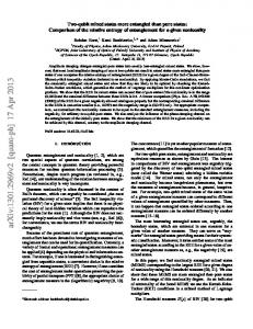
BSS consisting of the combination of a λ/2 polarization rotator and of a calcite crystal. Furthermore micrometric changes of the mutual phase ϕ of the kS and kA modes interfering on BSA were obtained by a piezoelectrically driven mirror M. All detectors were Si-avalanche EG&G-SPCM200 counting modules having nearly equal quantum efficiencies QE ≈ 0.45. Before detection the beams were IF filtered within a bandwidth 20nm. In Figure 1 the complete scheme for “active” teleportation is shown, including the highvoltage Pockels cell (EOP) inserted on the mode kB . In the same figure is reported the interferometric scheme for “passive teleportation” which is also adopted for the verification of the correct implementation of the “active” protocol, as we shall see. We have realized experimentally the passive teleportation protocol. By this we mean that Bob does not modify his state according to the results obtained by Alice. Instead Bob passes his state unmodified to the verification
7
stage. The verification stage consists in combining the mode ks (which now contains the teleported state) with the ancilla mode kea at a beam-splitter
BSB , as said. In order to check the overall mode alignment we first checked
at Alice’s site the 2-photon Ou-Mandel interference across the beam-splitter BSA between the modes kS and kA that are coupled to detectors D1 and D2 respectively. We obtained a 2-photon interference pattern with a visibility VA ≈ 0.96. In a similar way we checked, at Bob’s site the Ou-Mandel interference across BSB between the modes kB and kea coupled to the respective detectors D1∗ , D2∗ obtaining: VB ≈ 0.92. The QST verification experiment has been carried out first with a 50:50 beam splitter BSS , i.e. with optical 1
parameters: |rS | = |tS | = 2− 2 . The maximum visibility of the verification fringe pattern is obtained by selecting the same values of the parameters for the test beam splitter BSB , as said. Then we measured the coincidence counts between D1 , D2 and D1∗ , D2∗ . By a straightforward calculation we expect (D1 − D1∗ ) = (D2 − D2∗ ) =
1 ϕ 1 2ϕ sin , (D1 − D2∗ ) = (D2 − D1∗ ) = cos2 (5) 2 2 2 2
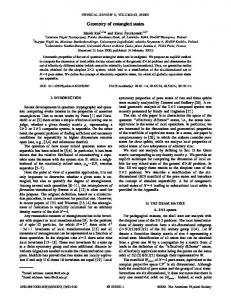
where (Di − Dj∗ ) expresses the probability of a coincidence detected by the pair Di , Dj∗ in correspondence with the realization of either one of the states: |Ψ3 iSA , |Ψ4 iSA . The experimental plots shown in Figure 2, obtained by varying the position X = (2)−3/2 λϕ/π of the mirror M, are in agreement with the theory, Eq. 5. This agreement is further substantiated by the data reported in Fig. 3 corresponding to a similar QST verification experiment carried out with a different set of optical parameters for BSB : |rB |2 = 0.20, |tB |2 = 0.80. Precisely, each experimental point of Fig. 3 corresponds to an experiment equal to the one referred to by Fig. 2. The visibility of 8
each sinusoidal fringe pattern is then reported. Note that the maximum visibility V is attained for values of α2 = 1 − β 2 that are equal to |rB |2 or to |tB |2 depending on which pair of detectors are excited. The two different peaks collapse into only one maximum with theoretical V = 1 in the fully symmetric case: |rB |2 = |tB |2 = α2 = β 2 = 12 . In Fig. 3 is also reported a single experimental value V ≃ 0.91 related to the symmetric case. Note that by assuming perfect detectors, i.e. with QE = 1, the above QST verification procedure involving the ancilla mode kea enables a fully noise-free teleportation procedure. Indeed, if no photons are detected at Alice’site, i.e. by D1 and/or D2 , while photons are detected at Bob’s site by D1∗ and/or D2∗ we can safely conclude that the “idle” Bell state |Ψ1 iSA has been created. If, on the other hand, no photons are detected at Bob’s site while photons are detected at Alice’s site, we must conclude that the other “idle” Bell state |Ψ2 iSA has been realized. The data collected in correspondence with these “idle” events can automatically be discarded by the electronic coincidence circuit. In addition to that, note that the effect of the above verification procedure involving the ancilla mode kea keeps holding within the
active teleportation scheme. Indeed, if the D2 − driven EO phase-modulator
works correctly within the active scheme, the detector D2∗ should be found to be always inactive. Our present effort is directed towards the completion of the teleportation picture by the realization of the “active” scheme. The main technical problem resides in the relatively large time needed to activate a high-voltage EO device by a single photon detection. The best result we have attained so far for the 1KV switching time across an EO modulator is about 10 nsec.
9
This figure would enable us to achieve the goal in the near future by the adoption of small λ/2 − voltage EO devices possibly in conjunction with the use of optical fibers. We are greatly indebted with the FET European Network on Quantum Information and Communication (Contract IST-200029681:ATESIT) and with M.U.R.S.T. for funding.
References [1] C. Bennett, G. Brassard, C. Crepeau, R. Jozsa, A. Peres and W. Wootters, Phys. Rev. Lett.70, 1895 (1993). [2] L. Vaidman, Phys. Rev. A, 49, 1473 (1994). [3] D. Boschi, S. Branca, F. De Martini, L.Hardy and S. Popescu, Phys. Rev. Lett. 80, 1121 (1998). [4] D. Bouwmeester, J. M. Pan, K. Mattle, M. Eibl, H. Weinfurter and A.Zeilinger, Nature 390: 575 (1997). [5] A. Furusawa, J. L. Sorensen, S. L. Braunstein, C.A. Fuchs, H. J. Kimble and E. S. Polzik, Science, 282, 706 (1998). [6] M. Nielsen, E. Knill and R. Laflamme, Nature 396: 52 (1998). [7] E. Knill, R. Laflamme and G. Milburn, Nature 409: 46 (2001). [8] Hai-Wong Lee and J. Kim, Phys. Rev. A, 63, 012305 (2000). [9] Hai-Wong Lee, Phys. Rev. A, 64: 014302 (2001). [10] Y.Aharonov private communication 10
[11] B. Oliver, C.Stroud Jr. Phys. Lett A 135 407 (1989). [12] S. Tan, D. Walls, M. Collet, Phys. Rev. Lett.66, 252 (1991). [13] L. Hardy, Phys. Rev. Lett 73 2279 (1994) [14] F. De Martini in Experimental Quantum Computation and Information, C. Monroe and F. De Martini editors (IOS, Amsterdam 2001). [15] D. F. Walls and G. Milburn, Quantum Optics (Springer, Berlin 1995) Ch.3. [16] C. Monken, P. Souto Ribeiro and S. Padua, Phys. Rev. A, R2267 (1998) and 57:3123 (1998).
11
Figure Captions
1. Experimental apparatus realizing the “active” and “passive” quantum state teleportation (QST). 2. Interferometric fringe patterns obtained by coincidence experiments involving different pairs of detectors within a passive QST verification procedure. 3. Visibility V of the coincidence fringe patterns Vs the superposition parameter α2 = 1 − β 2 obtained by two different pairs of detectors within a passive QST experiment and for an unbalanced beam splitter BSB with optical parameters |rB |2 = 0.20, |tB |2 = 0.80. The continuous lines represent the corresponding theorical expectations. A single experimental value of V for the fully symmetric case |rB |2 = |tB |2 = α2 = 0.50 is also reported.
12
BSS
BS 1,0
1,2
50 0
coincidence counts
coincidence counts coincidence counts
BSB
100
0,8
1,0
1,2
1,4
D1 *
BOB
D2 *
Mirror position X ( µm)
1,6
300 200 100 0
0,8
1,0
1,2
1,4 Mirror position X ( µm)
1,6
250
coincidence counts
D 2 - D 2*
EOP sz
150
1,6
Mirror position X ( µm)
250 200
1,4
400
kã
kB
300
0,8
ALICE
100
D 1 - D 2*
M
k2
D2
200
500
X D1 k1
300
0
kS
BSA
kA
D 1 - D 1*
400
200
D 2 - D 1*
150 100 50 0
0,8
1,0
1,2
1,4
Mirror position X ( µm)
1,6
100
visibility (%)
80 60 40 20 0 0,0
D 1 - D 1* D 1 - D 2*
0,2
0,4
α
2
0,6
0,8
1,0