Jul 6, 2012 - spin torque current to the junction. Either way it is a rather ... (e.g., that of a nano island).17â19 As a test subject we use a well-established .... leads to local oscillation of the TMR, which can be directly measured in an STM ...
PHYSICAL REVIEW B 86, 045409 (2012)
Local tunneling magnetoresistance control with surface-state confinement and external electric field Pavel A. Ignatiev, Oleg O. Brovko, and Valeri S. Stepanyuk Max-Planck-Institut f¨ur Mikrostrukturphysik, Weinberg 2, D-06120 Halle, Germany (Received 9 March 2012; published 6 July 2012) On the basis of density functional calculations, the possibility of using spin-polarized confinement and band structure manipulation by means of external electric fields to tune the local spin polarization of electrons and the local magnetoresistance ratio of a tunneling junction is discussed. To illustrate the concept, a model system of a bilayer Co island supported on a Cu(111) surface is used. DOI: 10.1103/PhysRevB.86.045409
PACS number(s): 73.20.At, 75.75.Lf, 71.15.Mb, 75.76.+j
Band structure manipulations are the key concept of modern electronics technology. Desired effects (logic element switching in most cases) are usually achieved by altering electrostatic potentials in multiterminal devices through applying bias voltages to the gate terminals.1 When it comes to data storage, however, magnetic units are the main workhorse. The advantages are obvious: high nonvolatility, relatively short switching times, and low production costs. There are, however, also drawbacks. The magnetic storage media has to be interfaced with electronic transport and processing channels, which usually involves electron currents and associated heat dissipation and energy consumption requirements. In the last decade the idea of replacing the current-driven electronics components by magnetic (spin) based units and optical interconnections (fashionably called spintronics) has inspired a lot of fundamental research. The vast variety of spintronic devices and their prototypes deal with tunneling magnetoresistance,2 which describes the dependence of the current through a sandwich junction (I ) made of two magnetic layers interspaced with a para- or diamagnetic separator on the mutual magnetization orientation of the magnetic leads (↑↑ of ↓↑).2–4 The measure of that dependence is the tunneling magnetoresistance ratio (TMR) defined as5 TMR =
I↑↑ − I↓↑ . I↓↑
(1)
This ratio is usually defined by the junction geometry and is thus fixed at construction and assemblytime. The magnetization reversal (information recording) of one of the magnetic leads can then be achieved by applying a magnetic field or a spin torque current to the junction. Either way it is a rather energy intensive process, and finding a more effective way of switching the polarization (or, for that matter, changing the TMR altogether) is a rather lucrative venture. One option is to use the electric field (without a current) to control the TMR. To follow that path one needs to couple magnetic and electrostatic properties of the system. The conventional way of achieving that is resorting to multiferroic materials and magnetic semiconductors.6–9 Mechanisms responsible for magnetoelectric coupling can be related in the latter two cases to the field-induced structural changes and field-controlled concentration of interaction mediators, respectively. Here we contemplate, using ab initio calculations to support our arguments, the fundamental possibility of locally controlling the TMR with two basic effects: (i) band structure 1098-0121/2012/86(4)/045409(5)
TH-2012-28
manipulation through application of the external electric field10–16 and (ii) the spatial confinement of a quasifree two-dimensional electron gas (2DEG) to a closed geometry (e.g., that of a nano island).17–19 As a test subject we use a well-established model system of a bilayer Co island20,21 on a Cu(111) surface, which hosts a spin-polarized surface state.17–19,22 I. SPIN-POLARIZATION AND CONDUCTANCE
In spin-polarized STM experiments the actual spinpolarization of the sample is usually determined or approxdI imated from the asymmetry of the differential conductance dV at parallel ↑↑ and antiparallel ↑↓ alignments of tip and sample magnetizations,2,18 A=
dI dV ↓↑ dI dV ↓↑
− +
dI dV ↑↑ . dI dV ↑↑
(2)
Using the theory of Tersoff and Hamann23,24 generalized for dI the magnetic case,25–27 the differential conductance dV can be rewritten as dI �T · m � S, (3) ∝ nT nS + m dV where nT and nS are the density of electronic states of the tip and the density of states created by the sample at the position of the tip, respectively, and m � T and m � S are defined in terms of local spin polarizations as m � = (n↑ − n↓ )μ � = (n↑ + n↓ ) P μ, �
(4)
μ � being a unit vector defining the direction of the spin moment and P being the local spin polarization, defined as n↑ − n↓ P = . (5) n↑ + n↓ Combining all together we obtain the following expression: A ∝ −PS PT ,
(6)
where PS and PT are polarizations of the sample and the tip, respectively. It should be noted that all the values mentioned above are understood to be energy-dependent quantities, so that, i.e., n↑(↓) = n↑(↓) (E) and P = P (E). In the same manner, polarizations PS and PT can be related to the TMR. Indeed, according to Julliere’s formalism,2 the tunneling current can be written as
045409-1
I (E) = I0 (E)(1 + PT (E) PS (E) μ �T · μ � S ).
(7)
©2012 American Physical Society
IGNATIEV, BROVKO, AND STEPANYUK
PHYSICAL REVIEW B 86, 045409 (2012)
Using this formula in Eq. (1), we easily obtain for the TMR TMR(E) =
2 PT (E) PS (E) . 1 − PT (E) PS (E)
(8)
Polarizations of the tip and the surface states are of the order of 10–20%. This means that |PT PS | � 1 and allows us to estimate the TMR behavior by expanding (8) in a Taylor series of �(E) = PT PS (E). If we further assume that the polarization of the tip remains largely unchanged (PT ≡ const), we get � � TMR(E) � 2�(E) + O(�2 (E)) ∝ PS (E) + O PS2 (E) . (9) It means that at small tip and sample polarizations, the TMR is proportional to the STS spin-asymmetry with an opposite sign. Thus the TMR can be estimated from the polarizations of the tip and the surface28 alone. This conclusion was recently confirmed by two STS experiments performed on bilayer Co islands grown on Cu(111).18,19 In the following, based on the experimental evidence, we shall assume the polarization of the tip to be 20%. II. SPIN-POLARIZED SURFACE STATES ON COBALT NANOISLANDS
Since late 1990s it has been known that triangular bilayer Co islands can self-assemble on the (111) surface of Cu under certain environmental parameters (Co coverage, deposition or annealing temperature, etc.).29 Co deposited on Cu(111) forms islands of almost perfect triangular shape due to anisotropic edge diffusion. Islands can grow both on fcc and hcp sites of the supporting Cu(111) surface.22,29 Due to their large lateral extent such islands can harbor a surface state similar to that existing on Co monolayers. The spin-polarized nature of that surface states was theoretically predicted in 2003.20 It was shown that majority and minority states have principally different dispersion laws around the Fermi energy: While the majority state is a Shockley 2D freeelectron–like surface state, with a band bottom at −0.233 eV, its minority counterpart resides at much higher energies (∼0.8 eV). The minority valence band around the Fermi energy is dominated by a virtually nondispersive state with a high negative effective electron mass. These findings perfectly supported available STS results. Later, the spin-polarized nature of surface states on Co nanoislands was demonstrated directly by means of spin-polarized STS experiments.18,19,21,30 This difference in dispersion laws drew particular attention to the phenomenon of spin-polarized confinement of electrons on Co nanoislands.17,18,20,22 In a nutshell, while majority free-like Shockley surface state gets confined forming near and above the Fermi energy a pronounced standing wave pattern,17,18,21,22 minority states are nondispersive everywhere except a relatively narrow window of energies around 0.25 eV below the Fermi level.17,18,20–22 This can lead to the formation of standing waves of polarization.22 The sign of polarization is actually determined by the level of minority states. At energies where the minority local density of states (LDOS) dominates, the polarization is negative. Where majority LDOS has higher amplitude, the polarization is positive. Most interesting is, however, the situation when the densities of majority and
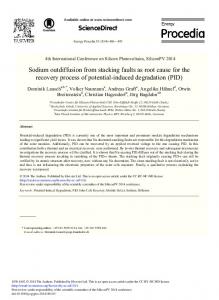
minority electrons are close. In this case the polarization can be positive on the crest of the majority standing wave and negative in its trough. Such local modulation of the polarization also leads to local oscillation of the TMR, which can be directly measured in an STM experiment.19 This is the first option of locally tailoring the TMR we wish to highlight in the present paper in more detail. The second way to tune TMR and spin-polarization relates to the band-structure manipulation by means of external bias (electric field). The fact that Shockley surface states are sensitive to applied external electric field has been recently discussed.10,31–33 The external electric field affects the evanescent tails of the surface state reaching into the vacuum. Fields directed toward the surface create an attractive potential, which weakens the confinement by the vacuum barrier and increases the spill-out of electrons which screen the external electric field. As a result the surface-state bands shift to lower energies and the surface-state local density of states increases in the vacuum. Oppositely directed fields have a contrary effect, i.e., they confine electrons and raise the surface-state binding energies. If surface states are spin-polarized, then majority- and minority-spin electrons are affected differently. It thus stands to reason that changing the band structure with external bias, we also change the spin-polarized confinement features discussed above and with them the local TMR ratio. Now let us see how those two concepts work in practice or, to be quite precise, in theory. To this end we have studied the band structures of bilayer Co nanoislands on a Cu(111) surface with a well established density functional theory technique: the Korringa-Kohn-Rostoker Green’s function (KKR-GF) method suitable for dealing with electric fields.10 The calculations are carried out in nonrelativistic collinear spin approximation. For our calculations we have chosen an island two atomic layers high and with a base length of ∼12 nm—the same size as was considered in Ref. 18. In the latter work it has been shown that KKR is a highly suitable tool for studying the kind of electron confinement we discuss here. The spectral electron density maps (SDM)34 of majority ˚ above a Co bilayer without and minority electrons some 5 A an external field are presented in Fig. 1(a). As expected, the majority Shockley surface state [traced by a red line in the upper panel of Fig. 1(a)] can be observed inside the projected bulk band gap of the Cu(111) surface [the outline of the gap is denoted by dashed lines in Fig. 1(a)]. The surface-state binding energy is −0.25 eV. Minority states [traced by a blue line in the lower panel of Fig. 1(a)] form a lightly dispersive band stemming from the d states in the Co bilayer. This band has a negative effective mass and a binding energy of −0.1 eV. Where it crosses the boundary of the band gap and overlaps with the Cu(111) bulk states, surface resonances appear [at about −0.4 eV in Fig. 1(a)]. Both majority and minority surface-state bands are shifted in energy upon exposure to the external electric field. This phenomenon (the so-called screening) is illustrated in Fig. 1(b). Here the band structure of the same bilayer Co nanoisland ˚ is presented. exposed to an external electric field of +0.6 V/A The positive sign corresponds to fields directed toward the surface. Aside from the apparent energy shift of the bands, it can be noted that while the majority surface state remains virtually unchanged in shape (shifts rigidly), the minority band
045409-2
LOCAL TUNNELING MAGNETORESISTANCE CONTROL . . .
Κ
Μ
Κ (b)
0.0 V/Å
Γ
Μ
Κ Hi
0.6 V/Å
-0.1 -0.2 -0.3 -0.4 -0.5
maj
maj
k
0V/Å 0.1eV
k 0.6V/Å F
0.2 0.1 0.0 -0.1 -0.2 -0.3
EEF band shift
-0.4 -0.5
Κ
Γ
Μ
(d) 0.1
-0.1
0.0 E0 (eV)
0.0 -0.2 -0.3 -0.4 min 0.1 Γ 0.1 k(1/Å)
Μ
min
Κ
0.1 Γ 0.1 k(1/Å)
Μ
maj
min
-0.1
0.2 -0.2
-0.2 -0.3
Κ
0.6
maj
-0.6
m* (me)
E-EF (eV)
k 0V/Å F
Μ
Lo
0.2 0.1
-0.5 -0.6
Γ
(c)
E-EF (eV)
E-EF (eV)
Γ
spectral density
0.2 (a) 0.1 0.0
PHYSICAL REVIEW B 86, 045409 (2012)
min -1.0
-0.4 -0.6 0.0 0.6 -0.6 0.0 0.6 EF (V/Å) EF (V/Å)
FIG. 1. (Color) Spectral density maps of majority (top panels) and minority (bottom panels) states along the K − �¯ − M path in the vicinity ˚ and (b) +0.6 V/A. ˚ The boundaries of the projected band gap of Cu(111) are lined by of the �¯ point plotted for electric fields of (a) 0.0 V/A dashed contours. The bands are traced by red (majority) and blue (minority) lines. (c) The sketch of the band structure and the field induced ˚ Majority and shifts. The dashed lines show the zero external field case. The solid lines stand for the band structure in the field of 0.6 V/A. minority bands are plotted with red blue curves, respectively. Gray shaded area shows the bulk states continuum. (d) The binding energies (E0 ) and effective masses (m∗ ) of majority (red circles) and minority (blue squares) surface bands are plotted.
becomes less dispersive (the effective mass is increased in ˚ amplitude). Switching the applied electric field from +0.6 V/A ˚ shifts the binding energies of majority and to −0.6 V/A minority states from −0.37 to −0.12 eV and from −0.25 to +0.07 eV, respectively. In this case both majority and dispersive minority states are nonzero at the Fermi energy. The shifting of the bands under the influence of the external electric field is sketched in Fig. 1(c), and the summary of the bandbottom positions and effective masses is given in Fig. 1(d).
III. STANDING WAVE PATTERNS AND TMR
Now let us see how the spin-polarized confinement and the external field sensitivity of the surface bands can be used to locally control the polarization of surface electrons and TMR ratio. As discussed above, in the absence of an external electric field the majority band of the surface state above a bilayer Co island has a binding energy of −0.233 eV and an effective 0V/A mass of 0.52me . This band crosses the Fermi energy at kF = −1 ˚ . The corresponding Fermi wave vector is shown in 0.127 A Fig. 1(c). The minority band lies below the Fermi energy and has a negative effective mass and hence has no corresponding Fermi wave vector. The minority states, however, still create a background density which contributes to spin polarization. The confinement of majority electrons at the Fermi energy by the vacuum potential at the boundaries of the island produces
a standing wave pattern shown in Fig. 2(a). The characteristic lateral dimension of the standing wave pattern is in accord with 0V/A ˚ the expected Fermi wave length of λF = π/kF = 24.7A. The minority electrons are not expected to be confined, which is indeed the case [see inset in Fig. 2(a)]. If we now use Eq. (8) to calculate the local TMR ratio, we obtain the distribution shown in Fig. 2(b). At the edge of the island the TMR is dictated by the prevailing minority edge states [inset Fig. 2(a)] and is positive (red color code) while in the center of the island the densities of majority and minority are comparable and the standing wave patterns in the majority density determine the polarization and the TMR ratio. The latter varies from almost 0 (white) to −22% (blue). If we now leave the Fermi energy and regard the TMR at EF + 0.1 eV the picture immediately changes. By going to higher enrgies we will have changed the effective wave 0V/A ˚ −1 vector of the majority surface state from kF = 0.127 A 0V/A ˚ −1 [Fig. 1(c)] and the associated electron to k 0.1 eV = 0.150 A ˚ This is promptly reflected in the wavelength to λF = 20.6 A. standing wave pattern of the majority electron density of states [Fig. 2(c)]. The density of minority states is further decreased in the interior of the island, but shows no qualitative behavior change, so that the resulting changes in TMR are mainly determined by the changes in majority electron confinement. The resulting TMR map is shown in Fig. 2(d). As compared to the map at the Fermi energy [Fig. 2(b)], local TMR has been
045409-3
(a)
EFext = 0.0 V/Å ΔE = 0 eV
PHYSICAL REVIEW B 86, 045409 (2012)
(c)
EFext = 0.0 V/Å ΔE = 0.1 eV
EFext = 0.6 V/Å ΔE = 0 eV
0.021 1/eV 0.042 1/eV
0.037 1/eV 0.086 1/eV
ρ
ρ (min)
↑(↓ )
0.022 1/eV 0.039 1/eV
(e)
(d) + 52 % – 23 %
TMR (%)
(f) + 60 % – 26 %
TM R(
%)
(b) + 47 % – 22 %
ρ (maj)
IGNATIEV, BROVKO, AND STEPANYUK
FIG. 2. (Color) Electron density of states for EF (�E = 0) (a) and EF + 0.1 eV (�E = 0.1 eV), (c) in zero external electric field ˚ (e) are plotted for majority and minority (insets) electrons. The colormap ˚ and for EF in an external field of EF = 0.6 V/A (EF = 0.0 V/A), is given on the right of the figure. The numbers next to electron density of states distributions denote (top to bottom) the current strength of the external electric field, the electron energy for which the map is plotted and the maximum values of the majority (red) and minority (blue) electron densities. The minimal values are always 01/eV (white). Subfigures (b), (d), and (f) show the TMR distribution maps for the above cases, calculated with Eqs. (8) and (5). The polarization of the tip has been assumed to be 0.2. The numbers next to the maps denote the boundaries of the colorscale. White always corresponds to zero TMR.
significantly altered in many parts of the island. Local maxima have replaced local minima and vice versa. Qualitatively similar changes can be made to the TMR distribution without straying from the Fermi energy. For that we can use our second tool, the external electric field. For example, by exposing the nanoisland to an external field of ˚ we shift both majority and minority bands downward 0.6 V/A in energy by 0.133 and 0.164 eV, respectively [Figs. 1(c) and 1(d)]. For the electrons at the Fermi energy it means, that the influence of the minority state is once again reduced and the majority surface-state band crosses the Fermi energy at 0.6 V/A ˚ −1 of 0.152 A higher k’s, giving the majority electrons a kF [Fig. 1(c)]. It is now clear that the energy shift of 0.1 eV in the last example has not been chosen randomly, but rather to provide the same electron wave vector as the Fermi wave ˚ Since the two vector in an applied external field of 0.6 V/A. wave vectors are equal it is logical to assume, that the resulting electron density of states distributions and TMR maps shall be very similar. This is indeed the case. The electron density of states and TMR maps for an island in an external field of ˚ are shown in Figs. 2(e) and 2(f), respectively. While 0.6 V/A the two TMR maps are fairly similar they are not identical. The existing difference is easy to explain, however. As has been discussed above, while the majority band is shifted relatively rigidly by the field, the effective mass of the minority band is changed slightly (incident fields make the band less dispersive) and the shift in energy for majority and minority bands are not
exactly the same [Fig. 1(d)]. Owing to this the TMR maps in Figs. 2(d) and 2(f) are not identical. Yet they share the same qualitative features, and it can be concluded that both changing the observation energy and applying external electric fields are effective methods of locally tailoring the polarization and TMR ratio of electrons confined to bilayer Co nanoislands. It can be noted, that if we apply the opposite electric field or go to lower energies for observations we shall eventually encounter an energy window where the minority states become dispersive [in the confines of the minority (blue) band in Fig. 1(c)]. At those energies either the confinement of minority electrons or both minority and majority confinements shall be the determining factor for the local polarization and TMR distributions. In the latter case the TMR map shall be composed of two overlapping standing wave patterns of different or similar wavelengths and is likely to be fairly complex.
IV. CONCLUSIONS
To summarize, we have demonstrated, that the external electric field results in nearly rigid linear shifts of binding energies of the spin-polarized surface bands above a bilayer Co nanoisland on a Cu(111) surface. Changes of energetics result in the altering of wave vectors for electrons of majority, minority, or both spin characters. Changes of wave vectors directly determine the local distribution of electron spin polarization and the derived local TMR ratio.
045409-4
LOCAL TUNNELING MAGNETORESISTANCE CONTROL . . . 1
Z. Alferov, Semiconductors 32, 1 (1998). M. Julliere, Phys. Lett. A 54, 225 (1975). 3 J. M. De Teresa, A. Barth`el`emy, A. Fert, J. P. Contour, F. Montaigne, and P. Seneor, Science 286, 507 (1999). 4 E. Y. Tsymbal, O. N. Mryasov, and P. R. LeClair, J. Phys.: Condens. Matter 15, R109 (2003). 5 S. S. P. Parkin, C. Kaiser, A. Panchula, P. M. Rice, B. Hughes, M. Samant, and S.-H. Yang, Nature Mater. 3, 862 (2004). 6 S. Picozzi and C. Ederer, J. Phys.: Condens. Matter 21, 303201 (2009). 7 K. F. Wang, J. M. Liu, and Z. F. Ren, Adv. Phys. 58, 321 (2009). 8 G. Lawes and G. Srinivasan, J. Phys. D: Appl. Phys. 44, 243001 (2011). 9 ˇ c, J. Fabian, and S. Das Sarma, Rev. Mod. Phys. 76, 323 I. Zuti´ (2004). 10 P. A. Ignatiev and V. S. Stepanyuk, Phys. Rev. B 84, 075421 (2011). 11 S. Zhang, Phys. Rev. Lett. 83, 640 (1999). 12 S. Heinze, X. Nie, S. Bl¨ugel, and M. Weinert, Chem. Phys. Lett. 315, 167 (1999). 13 C.-G. Duan, J. P. Velev, R. F. Sabirianov, Z. Zhu, J. Chu, S. S. Jaswal, and E. Y. Tsymbal, Phys. Rev. Lett. 101, 137201 (2008). 14 K. Nakamura, R. Shimabukuro, Y. Fujiwara, T. Akiyama, T. Ito, and A. J. Freeman, Phys. Rev. Lett. 102, 187201 (2009). 15 M. Tsujikawa and T. Oda, Phys. Rev. Lett. 102, 247203 (2009). 16 M. K. Niranjan, C.-G. Duan, S. S. Jaswal, and E. Y. Tsymbal, Appl. Phys. Lett. 96, 222504 (2010). 17 L. Niebergall, V. S. Stepanyuk, J. Berakdar, and P. Bruno, Phys. Rev. Lett. 96, 127204 (2006). 18 H. Oka, P. A. Ignatiev, S. Wedekind, G. Rodary, L. Niebergall, V. S. Stepanyuk, D. Sander, and J. Kirschner, Science 327, 843 (2010). 2
PHYSICAL REVIEW B 86, 045409 (2012) 19
H. Oka, K. Tao, S. Wedekind, G. Rodary, V. S. Stepanyuk, D. Sander, and J. Kirschner, Phys. Rev. Lett. 107, 187201 (2011). 20 L. Diekh¨oner, M. A. Schneider, A. N. Baranov, V. S. Stepanyuk, P. Bruno, and K. Kern, Phys. Rev. Lett. 90, 236801 (2003). 21 M. V. Rastei, B. Heinrich, L. Limot, P. A. Ignatiev, V. S. Stepanyuk, P. Bruno, and J. P. Bucher, Phys. Rev. Lett. 99, 246102 (2007). 22 O. Pietzsch, A. Kubetzka, M. Bode, and R. Wiesendanger, Phys. Rev. Lett. 92, 057202 (2004). 23 J. Tersoff and D. R. Hamann, Phys. Rev. Lett. 50, 1998 (1983). 24 J. Tersoff and D. R. Hamann, Phys. Rev. B 31, 805 (1985). 25 J. C. Slonczewski, Phys. Rev. B 39, 6995 (1989). 26 D. Wortmann, S. Heinze, P. Kurz, G. Bihlmayer, and S. Bl¨ugel, Phys. Rev. Lett. 86, 4132 (2001). 27 R. Wiesendanger, Rev. Mod. Phys. 81, 1495 (2009). 28 To be precise, from the spin-polarized DOS of the surface at the position of the tip. 29 N. N. Negulyaev, V. S. Stepanyuk, P. Bruno, L. Diekh¨oner, P. Wahl, and K. Kern, Phys. Rev. B 77, 125437 (2008). 30 O. Pietzsch, S. Okatov, A. Kubetzka, M. Bode, S. Heinze, A. Lichtenstein, and R. Wiesendanger, Phys. Rev. Lett. 96, 237203 (2006). 31 L. Limot, T. Maroutian, P. Johansson, and R. Berndt, Phys. Rev. Lett. 91, 196801 (2003). 32 J. Kr¨oger, L. Limot, H. Jensen, R. Berndt, and P. Johansson, Phys. Rev. B 70, 033401 (2004). 33 K. Berland, T. L. Einstein, and P. Hyldgaard, Phys. Rev. B 85, 035427 (2012). 34 The SDM is a plot of the k vector and energy resolved local density of states at a point in vacuum for a set of k points along the K − �¯ − M line in the Brillouin zone and for a given energy window.
045409-5