27 May 2010 - The Z-Interference Channel with Conferencing Encoders. ..... X2rp and X2rc ? Again, we give the priority to X2rp , and name its share of the cooperative capacity ...... [21] T. Cover and J. Thomas, Elements of information theory.
1
The Approximate Capacity Region of the Gaussian Z-Interference Channel with Conferencing Encoders arXiv:1005.1635v2 [cs.IT] 27 May 2010
Hossein Bagheri, Abolfazl S. Motahari, and Amir K. Khandani Department of Electrical and Computer Engineering, University of Waterloo Emails: {hbagheri, abolfazl, khandani}@cst.uwaterloo.ca
Abstract A two-user Gaussian Z-Interference Channel (GZIC) is considered, in which encoders are connected through noiseless links with finite capacities. In this setting, prior to each transmission block the encoders communicate with each other over the cooperative links. The capacity region and the sum-capacity of the channel are characterized within 1.71 bits per user and 2 bits in total, respectively. It is also established that properly sharing the total limited cooperation capacity between the cooperative links may enhance the achievable region, even when compared to the case of unidirectional transmitter cooperation with infinite cooperation capacity. To obtain the results, genie-aided upper bounds on the sum-capacity and cut-set bounds on the individual rates are compared with the achievable rate region. In the interference-limited regime, the achievable scheme enjoys a simple type of Han-Kobayashi signaling, together with the zero-forcing, and basic relaying techniques. In the noise-limited regime, it is shown that treating interference as noise achieves the capacity region up to a single bit per user.
I. I NTRODUCTION Interference limits the throughput of a network, consisting of multiple non-cooperative transmitters, intending to convey independent messages to their corresponding receivers through a common bandwidth. The way interference is usually dealt with is by either treating it as noise or preventing it by associating different orthogonal dimensions, e.g. time or frequency division to different users. Since interference has structure, it is possible for a receiver to decode some part of the interference and remove it from the received signal. This is indeed the coding scheme proposed by Han-Kobayashi (HK) for the two-user Gaussian Interference Channel (GIC) [1]. The two-user GIC provides a simple example showing that a single strategy against interference is not optimal. In fact, one needs to adjust the strategy according to the channel parameters [2]–[4]. However, a single suboptimal strategy can be proposed to achieve up to 1 bit per user of the capacity region of the two-user GIC [5]. Financial support provided by Nortel and the corresponding matching funds by the Natural Sciences and Engineering Research Council of Canada (NSERC), and Ontario Ministry of Research & Innovation (ORF-RE) are gratefully acknowledged.
May 28, 2010
DRAFT
2
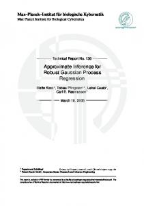
If the senders can cooperate, interference management can be done more effectively through cooperation. Cooperative links can be either orthogonal or non-orthogonal to the shared medium. In this work, orthogonal cooperation is considered. In addition, in order to understand some fundamental aspects of the optimal coding scheme (in the sense of having a constant gap to the capacity region), the GZIC is investigated, in which one transmitter-receiver pair is interference-free (see Fig. 1.). Prior Works. Transmitter coordination over orthogonal links is studied for different scenarios with two transmitters (cf. [6]–[14]). The capacity region of the Multiple Access Channel (MAC) with cooperating encoders is derived in [6], where cooperation is referred to as conference. Several achievable rate regions are proposed for the GIC with bidirectional transmitter and receiver cooperation [7]. In the transmit cooperation, the entire message of each transmitter is decoded by the other cooperating transmitter, which apparently limits the performance of the scheme to the capacity of the involved cooperative link. The capacity regions of the compound MAC with conferencing encoders and the GIC with degraded message set, under certain strong interference conditions, are obtained in [8]. The GIC with degraded message set is also termed Gaussian Cognitive Radio (GCR) in the literature [9]. The GCR can be considered as a GIC with unidirectional orthogonal cooperation, in which the capacity of the cooperative link is infinity.1 The capacity region of the GCR is established for the weak interference regime in [10], [11]. Recently, the capacity region of the GCR is characterized within 1.87 bits for all ranges of the channel parameters [12]. Furthermore, the sum-capacity of the symmetric GIC with unidirectional and bidirectional cooperation is approximated up to 2 and 2.13 bits, respectively in [13], [14]. The achievable schemes are based on a simple type of HK scheme, cooperative communication, and zero-forcing technique. For non-orthogonal cooperative links, an achievable rate region is proposed in [15] and the sum-capacity of the GIC is determined up to 18 bits [16]. Very recently, in a parallel and independent work, the capacity region of the GIC with bidirectional cooperation is characterized within 6.5 bits [20].2 Contributions and Relation to Previous Works. Simple achievable schemes based on HK, relaying and zeroforcing techniques are shown to achieve the capacity region within 1.71 bits per user for all channel parameters.3 In this paper, some important features of the problem are explored one-by-one and the appropriate achievable schemes are proposed accordingly. In the first step, the GZIC with unidirectional cooperation is considered. It is demonstrated that the HK scheme together with zero-forcing or relaying can achieve the capacity region up to 1.5 bits per user. Then, based on the observations made in the unidirectional case, the capacity region of the GZIC with bidirectional cooperation is determined up to 1.71 bits per user. Our step-by-step approach to solve the problem is in contrast to the universal strategy of [20], in which the same signaling is used for all channel parameters. 1 Technically, 2 An
the capacity of the cooperative link needs to be equal to the message rate of the user sending data via the cooperative link [6].
earlier version of our work containing most of the results is reported in Library and Archives Canada Technical Report UW-ECE 2010-04,
Feb. 2010 [19]. 3 It
is remarked that the binning technique [17] can be used at the encoder corresponding to the receiver with interference, to precode its
message against the known interference. This, in general, could enlarge the achievable rate region. However, it is shown that one can achieve the capacity region within 1.71 bits without using the binning technique.
May 28, 2010
DRAFT
3
N1 m1
ENC 1
X1
P1
1
Y1
m ˆ1
DEC 1
C12 m2
C21
q12
q21 X2 ENC 2
a P2
Y2
m ˆ2
DEC 2
1 N2 Fig. 1. The Z-Interference Channel with Conferencing Encoders. The cooperation links are orthogonal to each other and to the communication medium as shown with different colors in the figure. In the proposed achievable schemes, the cooperative links with capacities C12 and C21 are used for zero-forcing and relaying purposes, respectively.
Applying the scheme of [20] to the GZIC, five signals should be jointly decoded at each receiver, whereas three signals are required to be jointly decoded in our paper, which simplifies the transmission scheme. Appropriate compression and sequential decoding techniques are utilized to facilitate such a low complexity decoding. In the achievable schemes, proper power allocation over the employed codewords plays an essential role to achieve the result. The Linear Deterministic Model (LDM) proposed in [18] is incorporated to attain such a power allocation. It is illustrated that for some channel parameters, no cooperation or unidirectional cooperation is sufficient to obtain the results. It is also argued that a suitable distribution of total cooperation capacity between the cooperative links can enhance the rate region. In particular, it is demonstrated that the achievable region of the GZIC with limited bidirectional cooperation may outperform the capacity region of the GZIC with infinite unidirectional cooperation, known as the cognitive Z channel. When the noise is the performance-limiting factor instead of the interference, it is shown that treating interference as noise, and not using the cooperative links, achieve within 1 bit of the capacity region of the channel for all channel parameters. The rest of the paper is structured as follows. Section II describes the system model and the preliminaries. Section III presents an outer bound on the capacity region. Section IV focuses on the unidirectional cooperation case and provides achievable schemes employing zero-forcing or relaying techniques depending on which cooperative link is present. Then, Section V adjusts the achievable schemes proposed for the unidirectional case to the general bidirectional cooperation case. Section VI numerically compares the performance of bidirectional and unidirectional cooperation cases. Finally, Section VII concludes the paper. The detailed proofs and gap analysis are left to the appendices. Notation. Throughout the paper, all logarithms are to base 2, and C(P ) ,
1 2
log (1 + P ). The set of ǫ jointly (n)
typical sequences of random variables (xn , y n ), with length n, is represented by Aǫ (xn , y n ) (for the definition, see [21]). Whenever it is clear from the context, the random variables may be omitted from the notation.
May 28, 2010
DRAFT
4
II. S YSTEM M ODEL AND P RELIMINARIES In this work, a two-user GZIC with partial transmit cooperation, as depicted in Fig. 1, is considered. The model consists of two transmitter-receiver pairs, in which each transmitter wishes to convey its own data to its corresponding receiver. There exist two noiseless cooperative links with capacities C12 and C21 , respectively from Encoder 1 to Encoder 2 and vice versa. It is assumed that all nodes are equipped with a single antenna. The input-output relationship for this channel in standard form is expressed as [22]: Y1 = X1 + N1 ,
(1)
Y2 = aX1 + X2 + N2 , where a ≥ 0, and for i ∈ {1, 2}, Ni ∼ N (0, 1), i.e., is the Gaussian noise with zero mean and unit variance. The average power constraint of the transmitters are respectively P1 and P2 . The full channel state information is assumed to be available at both the transmitters and the receivers. For a given block length n, Encoder i ∈ {1, 2} sends its own (random) message index mi from the index set
Mi = {1, 2, ..., Mi = 2nRi } with rate Ri [bits/channel use]. Each pair (m1 , m2 ) occurs with the same probability 1 M1 M2 .
n n The result of the conference between the two encoders is two codewords q12 , q21 , where for j ∈ {1, 2}, i 6= j,
and each time index t ∈ {1, · · · , n}, qij [t] is only a function of (mi , qji [1], · · · qji [t − 1]). The encoding function fi
n maps the message index mi and qji into a codeword Xin chosen from codebook Ci . Therefore:
X1n
n = f1 (m1 , q21 ),
X2n
n = f2 (m2 , q12 ).
(2)
The codewords in each codebook must satisfy the average power constraint
1 n
n P
t=1
|Xi [t]|2 ≤ Pi . Each decoder uses
a decoding function gi (Yin ) to decode its desired message index mi based on its received sequence. Let m ˆ i be the ˆ i 6= mi ). A rate pair (R1 , R2 ) output of the decoder. The average probability of error for each decoder is Pei = Pr(m is said to be achievable when there exists an (M1 , M2 , n, Pe1 , Pe2 )-code for the GZIC consisting of two encoding functions {f1 , f2 } and two decoding functions {g1 , g2 } such that for sufficiently large n: 1 n
log(M1 ),
1 n
log(M2 ),
R1
≤
R2
≤
Pe
≤ ǫ.
In the above, Pe = max(Pe1 , Pe2 ) and ǫ > 0 is a constant that can be chosen arbitrarily small. The capacity region of the GZIC with conferencing encoders is the closure of the set of achievable rate pairs. The boundary of the achievable region R is said to be within (∆1 , ∆2 ) of the boundary of the upper bound region Rup if for any pair
(R1up , R2up ) on the boundary of the outer bound, there exists a pair (R1 , R2 ) on the achievable region such that R1up − R1 ≤ ∆1 , and R2up − R2 ≤ ∆2 . In this case, the achievable scheme leading to the region R is referred to as R(∆1 , ∆2 ) achievable.
If the regions associated with Rup and R(∆1 , ∆2 ) are polytopes, each facet of the achievable region is compared up
to its corresponding facet in the upper bound region. Defining δR1 , R1 − R1 , we have δR1 ≤ ∆1 . Similarly, for the facet related to iR1 +jR2 , for any i, j ∈ {1, 2, · · · }, we have δiR1 +jR2 ≤ i∆1 + j∆2 . May 28, 2010
DRAFT
5
1
1
C12
Fig. 2.
C21
a
a
1
1
(a)
(b)
Unidirectional Cooperation: (a) Zero-Forcing Scenario, (b) Relaying Scenario. The blue color represents the route of zero-forcing/
relaying.
In this work, the interference-limited regime is mainly investigated, i.e., a2 P1 ≥ 1, since otherwise the system is noise limited and is not of much interest. The noise-limited regime will be briefly considered in Section V. III. U PPER B OUNDS Lemma 1: The following region is an upper bound on the capacity region of the GZIC shown in Fig. 1: R1up ≤ C(P1 )
(3)
up
R2 ≤ C(P2 ) + C21 R2up ≤ C 2a2 P1 + 2P2
up
up
�
max{1−a2, 0}P1 )+C(2a2 P1 +2P2 )+C12 1+a2 P1 � ≤ C P1 P2 + P1 (1 + 2a2 ) + 2P2 .
R1up +R2up≤ C( R1 + R2
(4) (5) (6) (7)
Proof: The first three bounds are simple applications of cut-set bounds at Transmitter 1, Transmitter 2, and Receiver 2, respectively. The sum-rate upper bounds are the tailored version of the bounds obtained for the GIC √ √ with conferencing encoders in [14]. To simplify the gap analysis, the term ( a2 P1 + P2 )2 in [14] is replaced by the larger term 2a2 P1 + 2P2 in (5), (6), and (7). IV. U NIDIRECTIONAL C OOPERATION To gain some insight into the essential ingredients of an appropriate achievable scheme, first, it is assumed that one of the cooperative links has zero capacity. Depending on which capacity is zero, two scenarios can occur (see also Fig. 2): 1) C21 = 0 termed as zero-forcing scenario. 2) C12 = 0 termed as relaying scenario.
May 28, 2010
DRAFT
6
A. Zero-Forcing Scenario (C21 = 0) In this scenario, Transmitter 2 utilizes C12 to cancel the known part of the interference (Fig. 2 (a)). The rest of the signaling is similar to the one proposed for the conventional GIC [5]. In other words, Encoder 1 makes use of three independent codebooks4, namely private codebooks C1p and C1z , and common codebook C1c , with corresponding codewords X1p , X1z , and X1c . Encoder 2 uses two private codebooks C2p and C1z . X1z is available at both transmitters via the cooperative link and zero-forced at the second receiver. Since Transmitter 2 does not cause any interference on Receiver 1, there is no need to include a common codebook for User 2. The transmit signals are represented as follows: X1 = X1p + X1c + X1z , (8) X2 = X2p − aX1z . Decoders decide on the codeword indices i, j, k, and l according to: (n)
•
Decoder 1: (X1p (i), X1z (j), X1c (k), Y1 ) ∈ Aǫ ,
•
Decoder 2: (X1c (k), X2p (l), Y2 ) ∈ Aǫ .
(n)
Appendix A shows the rate region described by (9)-(11) is achievable: R1 ≤ min{C(P1 ), C(P1p +P1c )+C12 } R2 ≤ C(
(9)
P2p ) d
(10)
R1 + R2 ≤ min{C(P1p +P1z ), C(P1p )+C12 }+C(
a2P1c +P2p ), d
(11)
where d , 1 + a2 P1p .
(12)
The following observations are utilized to attain a suitable power allocation for different codewords: •
Since X1p is treated as noise at Receiver 2, we set P1p = a12 in order to receive X1p at the level of the Gaussian noise at Receiver 2 [5].
• •
up
To make R2 close to R2 , i.e., C(P2 ), we impose the constraint To make R1 in (9) close to
R1up ,
i.e., C(P1 ), we enforce
P1 −P1p 2
P2 2
≤ P2p .
≤ P1c . This requirement is more pronounced
when C12 = 0. For the last two items, the factor 2 in the denominators ensures a maximum loss of 0.5 bit compared to the case of P2p = P2 , and P1c = P1 − P1p . Therefore, to satisfy the above constraints, we select P1z according to: � � P1 − P1p P2 P1z = min , 2 . 2 2a
(13)
Lemma 2: The preceding achievable scheme is R(0.5, 1) achievable. Proof: See Appendix A. 4 Through
May 28, 2010
out the paper, it is assumed that all of the employed codebooks are Gaussian and independent of each other.
DRAFT
7
B. Relaying Scenario (C12 = 0) Here, it is assumed that C12 = 0. In this scenario, C21 is employed to help Encoder 1 relay some information for User 2 (Fig. 2 (b)). Based on the relaying capability (the relay power a2 P1 and the relay to destination channel gain a), three cases are recognized in this setup and for each case, a different achievable scheme is proposed: • • •
Non Cooperative Case: a2 P1 ≤ P2 + 1,
Common Cooperative Case: P2 + 1 < a2 P1 , a2 ≤ P2 + 1,
Private-Common Cooperative Case: P2 + 1 < a2 P1 , P2 + 1 < a2 .
Before we continue to describe the achievable schemes, we stress that, throughout the paper, we aim to keep the achievable schemes simple, at the expense of a slight increase in the gap from the upper bound. 1) Non Cooperative Case: a2 P1 ≤ P2 + 1: In this case, the cooperative link is not used because it can at most enhance R2 by one bit. The signaling is similar to the HK signaling developed for the GIC: X1 = X1p + X1c , (14) X2 = X2p . We set P1c = P1 − P1p with P1p =
1 a2
for a ≤ 1, and P1p = 0 for 1 < a. The decoding rules are: (n)
•
Decoder 1: (X1p (i), X1c (j), Y1 ) ∈ Aǫ ,
•
Decoder 2: (X1c (j), X2p (k), Y2 ) ∈ Aǫ ,
(n)
which lead to the R(0, 1.5) achievable region below: R1 ≤ C(P1 )
(15)
R2 ≤ C(
(16)
P2 ) d
R1 + R2 ≤ C(P1p ) + C(
a2 (P1 − P1p ) + P2 ). d
(17)
See Appendix B-A for details. 2) Common Cooperative Case: P2 + 1 < a2 P1 , a2 ≤ P2 + 1: For this case, in addition to the signals transmitted in the non cooperative case, User 1 relays some data communicated over the cooperative link for User 2. The signaling is as follows: X1 = X1p + X1c + X2r , (18) X2 = X2p , where all signals are independent of each other. To find out how to treat X2r at Receiver 1 and how to allocate the Transmitter 1’s power between X1c and X2r , the deterministic model shown in Fig. 3, is used. The model demonstrates the power level interaction of the interfering signals according to the channel parameters. Since, X1p is received below the noise level of Decoder 2, it is considered as noise at that receiver. When two signals are at the same power level at a decoder, they need to be decoded jointly at that receiver. It is clear that there is not much benefit in having two signals with the same power level intended for the same receiver.5 Having said that, it 5 One
can infer that in the non cooperative case, the relayed signal is not required (in the constant gap sense). This is because in the
corresponding LDM (not shown in the paper), X2p and X2r would share the same power level.
May 28, 2010
DRAFT
8
1 0. It can be seen that for scenarios A, B, and E, the sum-capacity is approximated within 2 bits. In the following, scenarios C and D are further elucidated. Appendices C-C, and C-D argue the same gap holds for scenarios C and D, which assures the maximum gap of 2 bits on the sum-capacity for all regimes. C. P2 + 1 ≤ a2 P1 , a ≤ 1 A natural generalization of the schemes proposed for the unidirectional cooperation case, is to consider the following signaling: X1 = X1p + X1c + X1z + X2r , X2 = X2p − aX1z , May 28, 2010
DRAFT
11
where X2r is decoded at both receivers. To avoid the complexity of jointly decoding of four signals at Receiver 1, User 1’s private signal is compressed and sent to the other transmitter via the cooperative link with capacity C12 .7 Then, Transmitter 2 zero-forces the compressed version of the signal. In particular, the following signaling is used: X1 = X1p + X1c + X2r , (25) ˆ 1p , X2 = X2p − X ˆ 1p +Z, with Z∼ N (0, 1). The compression, imposes where aX1p is compressed with distortion 1, i.e., aX1p = X
the constraint C(a2 P1p −1) ≤ C12 . For the power allocation, it is recalled from the unidirectional cooperation case
that at most half of Transmitter 2’s power is allocated for zero-forcing to not harm its own maximum rate by more than half a bit. Therefore, the following power allocation is considered: min{22C12 , P22 + 1} , a2 P1 − P1p , = 2
P1p = P1c = P2r
(26)
P2p = P2 − (a2 P1p − 1). The term containing C12 is due to the compression rate constraint. Lemma 5: The region given in (19)-(22) is R(0.5, 1.71) achievable. Proof: See Appendix C-C. D. P2 + 1 ≤ a2 P1 , 1 ≤ a2 ≤ P2 + 1 In this regime, the zero-forcing technique used for C21 = 0, and the relaying technique used for C12 = 0 are simply combined, i.e., X1 = X1z + X1c + X2r , (27) X2 = X2p − aX1z . Similar to the unidirectional case, the following power allocation is used: P2 , 2a2 P1 − P1z = , 2 P2 = . 2
P1z = P1c = P2r P2p
7 Instead
of the compression, one might sequentially decode (X1c , X1z , X2r ) and X1p , similar to the approach of Section IV-B3.
May 28, 2010
DRAFT
12
Lemma 6: The following region is R(1, 1.21) achievable:
P2 P1 + 2a 2 ) 2 P2 P1 − 2a 2 ≤ C( ) + C12 2 P2 ≤ C( ) + C21 2 2a2 P1 + P2 ≤ C( ) 4 1 ≤ C(a2 P1 ) + C12 − 2 1 P2 ≤ C(a2 P1 ) + C( 2 ) − 2a 2 P2 1 ≤ C(P1 ) + C( ) − . 2 2
R1 ≤ C(
(28)
R1
(29)
R2 R2 R1 + R2 R1 + R2 R1 + R2
(30) (31) (32) (33) (34)
Proof: See Appendix C-D. VI. B IDIRECTIONAL V. S . U NIDIRECTIONAL C OOPERATION : A N UMERICAL A NALYSIS V IEW In the previous section, it has been observed that unidirectional cooperation is optimum in the constant gap sense for the following two cases: 1 ≤ a2 P1 ≤ P2 + 1, and P2 + 1 ≤ min{a2 P1 , a2 }. In this section, however, various numerical results are presented to demonstrate that bidirectional cooperation between the transmitters may provide better rate pairs compared to the unidirectional cooperation with a relatively larger total cooperation capacity. To achieve this goal, it is assumed that the total cooperation capacity C , C12 + C21 is fixed and can be arbitrarily distributed between the cooperative links. The achievable region optimized over such distribution is compared to the capacity region or the outer bound region corresponding to the extreme case of unidirectional cooperation , i.e., the Cognitive Radio Z Channel (CRZC).8 The CRZC can be either in the form of Fig. 2 (a) or Fig. 2 (b). The former and the latter forms, respectively called type I and II, serve as the baseline for comparison in Figs. 5 and 6, respectively. The capacity regions of the type I CRZC (for all a values), and type II CRZC (for a ≤ 1) are expressed by: R1up ≤ C(P1 ) R2up ≤ C(P2 ), 8 In
the cognitive setup, the cognitive transmitter knows the whole message of the primary user [8]. This property can be modeled as having a
GIC with unidirectional transmitter cooperation. In such a configuration, the capacity of the cooperative link suffices to be equal to the message rate of the primary user. This fact is described for the MAC with conferencing encoders in [6]. In this section, it is shown that sharing that required capacity, or even smaller than that amount, between the bidirectional cooperative links can provide better rate pairs depending on the channel parameters.
May 28, 2010
DRAFT
13
a=0.8, P1=40 dB, P2=30 dB 6
a=25, P1=P2=30 dB C1+C2≥ 6
9 C1=∞ C2=0
7 4
C1+C2≥5 C1+C2=2 C1+C2=1
6
3
C1=∞, C2=0
5
C1+C2=1
R2
C1+C2=0
R2
C1+C2=3
8 C +C =4 1 2
5
4
C1+C2=2
2
C1+C2=3
1
C1+C2=5
C +C =0 1
2
3 2 C +C =4 1
2
1 0 0
1
2
3
4
5
6
7
0 0
1
R1
3
4
5
R1
(a) Fig. 5.
2
(b)
Sharing the cooperative capacity between bidirectional cooperative links can enhance the maximum of R2 compared to the type I
CRZC. For P2 + 1 ≤ a2 (not shown in this figure), the sum-rate can also be increased.
and the union of the regions over 0 ≤ ρ ≤ 1 R1up ≤ C(ρP1 ) ! p √ ( a2 (1 − ρ)P1 + P2 )2 up , R2 ≤ C 1 + a2 ρP1 respectively [10]. For type II CRZC with 1 < a, the upper bound region described by (3)-(7) with C12 = 0, and C21 = ∞ is used.
Figs. 5 and 6 evaluate the achievable rates for different values of the channel parameters.9 Looking at Fig. 5, it is
seen that sharing the cooperative capacity can significantly increase the maximum of R2 , with respect to the type I CRZC, as a gets larger. In contrast, Fig. 6 shows bidirectional cooperation with relatively smaller total cooperation capacity can substantially enhance the sum-rate compared to the type II CRZC. VII. C ONCLUSION It has been shown that for GZIC with bidirectional cooperation, R(1, 1.71) is achievable. As another outcome of the gap analysis, the sum-capacity of the channel has been determined up to 2 bits. To obtain the results, basic communication techniques including Han-Kobayashi, zero-forcing, simple relaying, and transmission at the noise level schemes are employed. In addition, with the aid of signal compression or sequential decoding methods, the decoding complexity of the utilized schemes is limited to jointly decoding of at most three independent signals at each receiver. It has been observed that unidirectional and bidirectional cooperation almost similarly perform (in the promised constant gap sense) in two scenarios: 1) C21 is not required when the relaying power is smaller than the direct transmission power, i.e., a2 P1 ≤ P2 +1. 9 To
make figures more readable, C1 , and C2 are used instead of C12 , and C21 , respectively.
May 28, 2010
DRAFT
14
a=0.8, P1=40 dB, P2=30 dB
a=2.5, P1=P2=30 dB
7
7 C1=0, C2=∞
5
1
C +C =0 2
R2
4
3
3
2
2
5
C1+C2=1 1
1
2
6
R2
4
C +C ≥ 5
C =0, C =∞ C1+C2≥ 7
6
C +C =2 1 2 C1+C2=3
2
C1+C2=2 C1+C2=3 C +C =5
1
C1+C2=0 C1+C2=1
1
C +C =4 1
2
1
2
C1+C2=4
0 0
1
2
3
4
5
6
0 0
7
1
R1
3
4
5
R1
(a) Fig. 6.
2
(b)
Sharing the cooperative capacity between bidirectional cooperative links can improve the sum-rate compared to the type II CRZC.
2) C12 is not necessary when the relaying power and the relay gain are sufficiently large, i.e., P2 + 1 ≤ a2 P1 , and P2 + 1 ≤ a2 .
Furthermore, it has been shown that properly sharing the total cooperative capacity between the bidirectional links can enhance the achievable rate pairs in some scenarios. A PPENDIX A ACHIEVABLE R ATE
AND
G AP A NALYSIS
FOR
Z ERO -F ORCING S CENARIO
The resulting rate constraints from error analysis at Decoder 1 are: R1p ≤ C(P1p ) R1z ≤ min {C(P1z ), C12 } R1c ≤ C(P1c ) R1p + R1z ≤ C (P1p + P1z ) R1p + R1c ≤ C(P1p + P1c ) R1z + R1c ≤ C(P1z + P1c ) R1p + R1z + R1c ≤ C(P1 ), and the constraints for Decoder 2 are: P2p ) d a2 P1c + P2p ), ≤ C( d
R2p ≤ C( R2p + R1c
where d is defined in (12). Note that there is no individual rate constraint on R1c at Decoder 2 because the joint typical decoder does not declare an error in the case that only X1c is wrongly decoded [23]. Fourier-Motzkin May 28, 2010
DRAFT
15
Elimination (FME) [24] is applied to obtain the constraints in terms of R1 , R1p + R1z + R1c , and R2 , R2p . Removing the redundant inequalities due to the polymatroid structure of the rate constraints at each decoder, leads to the region (9)-(11). To simplify the gap analysis, it is noted that the subsequent region is also achievable: P1 ) 2 P2 R2 ≤ C( ) 4 a2 P1 − 1 + P2 1 ) + C12 R1 + R2 ≤ C( 2 ) + C( a 4 min{a2 P1 − 1, P2 } + 2 max{a2 P1 − 1, P2 } R1 + R2 ≤ C( ) + C( ). 2a2 4 R1 ≤ C(
(35) (36) (37) (38)
It is clear that the preceding region is smaller than that of (9)-(11). To obtain this region, we use (13) and set P1c = P1 2
P1 − a12 2
and P2p =
P2 2
in the achievable region (9)-(11). In addition, in getting (35) and (38) we notice
≤ P1p + P1c and max{a2 P1c , P2p } ≤ a2 P1c + P2p . In the following, the region is compared to the upper bound
to show that R(0.5, 1) is achievable: (3) − (35) ≤ 0.5 (4) − (36) ≤ 1 (a)
(6) − (37) ≤ 1.5 (3) + (4) − (38) ≤ 1.5. By (i) ± (j), we mean the sum/difference of the right hand side of Eqs. (i) and (j). To attain (a), the fact that 2
,0}P1 C( max{1−a ) ≤ C( a12 ) is used. It is remarked that R1p < 1 for the case of 1 < a. Therefore, we can set P1p = 0, 1+a2 P1
i.e., we do not use X1p in order to simplify the scheme. It can be shown that R(0.5, 0.5) is achievable in this case. A PPENDIX B ACHIEVABLE R ATE
AND
G AP A NALYSIS
FOR
R ELAYING S CENARIO
In this appendix, the achievable rate and gap analysis corresponding to the three scenarios identified in Section IV-B are derived in detail. A. Non-Cooperative Case The decoding rules lead to the following rate constraints at Decoder 1 and Decoder 2: Decoder 1: R1p ≤ C(P1p ) R1c ≤ C(P1c ) R1p + R1c ≤ C(P1 ),
May 28, 2010
DRAFT
16
Decoder 2: P2 ) 2 P2 + a2 P1c ). ≤ C( 2
R2p ≤ C( R2p + R1c
Noting that a2 P1 − 1 ≤ P2 , it is straightforward to prove the region (15)-(17), which is obtained by applying FME, is R(0, 1.5) achievable. To find the worst case gap, (15), (16), and (17) are respectively compared to the upper bounds (3), (5), and (6). As in the conventional GIC for 1 < a, the private signal is not needed, and therefore, R(0, 1) is achievable. B. Common Cooperative Case (Proof of Lemma 3) The decoding rules impose the following constraints: Decoder 1:
R1p ≤ C(P1p )
(39)
R1c ≤ C(P1c )
(40)
R1p + R1c ≤ C(P1p + P1c )
(41)
R1p + R2r ≤ C(P1p + P2r )
(42)
R1c + R2r ≤ C(P1c + P2r )
(43)
R1p + R1c + R2r ≤ C(P1 ),
(44)
Decoder 2:
R2p ≤ C(
P2p ) d
a2 P2r )} d a2 P2r + P2p ) ≤ C( d 2 P2p + a P1c ≤ C( ) d a2 (P2r + P1c ) ) ≤ C( d P2p + a2 (P2r + P1c ) ), ≤ C( d
R2r ≤ min{C21 , C( R2p + R2r R2p + R1c R2r + R1c R2p + R2r + R1c
(45) (46) (47) (48) (49) (50)
where d is defined in (12). Defining R1 , R1p + R1c and R2 , R2p + R2r , applying FME, and removing redundant inequalities, lead to the following rate constraints:
May 28, 2010
DRAFT
17
R1 ≤ C(P1p + P1c ) R1 ≤ C(P1p ) + C(
(51) 2
a (P2r + P1c ) ) d
(52)
P2p ) + C21 d a2 P2r + P2p ) ≤ C( d P2p ≤ C(P1 ) + C( ) d P2p + a2 P1c ) + C(P1p + P2r ) ≤ C( d P2p + a2 (P2r + P1c ) ≤ C( ) + C(P1p ) d P2p + a2 P1c ) + C(P1p ) + C21 ≤ C( d P2p + a2 P1c a2 (P2r + P1c ) ≤ C( ) + C( ) + 2C(P1p ) d d P2p + a2 P1c ) + C(P1p ) + C(P1 ) ≤ C( d P2p + a2 (P2r + P1c ) P2p ) + C( ) + C(P1p + P2r ) ≤ C( d d P2p ≤ 2C( ) + C(P2r + P1c ) + C(P1p + P2r ). d
R2 ≤ C(
(53)
R2
(54)
R1 + R2 R1 + R2 R1 + R2 R1 + R2 2R1 + R2 2R1 + R2 R1 + 2R2 R1 + 2R2
(55) (56) (57) (58) (59) (60) (61) (62)
It is noted that (62) is redundant since (61) ≤ (62) as verified below for two cases of a ≤ 1, and 1 < a: (62) − (61) = (45) + (43) − (50) ≥ (45) + (49) − (50) ≥ 0
for a ≤ 1 (⋆)
= C(P2 )+C(P1 )−C(P2 +a2 P1 ) ≥ 0 for 1 < a, where to prove (⋆), a2 is replaced by its maximum value, i.e., P2 + 1. We set P2r = P1c =
P1 −P1p . d
This power allocation policy not only does not decrease the maximum rates of
both users by more than 0.5 bit, but also can simplify the achievable region by making some inequalities redundant. In particular, if we decrease (57) by 0.5 bit, then the region described by (19)-(22) is achievable. This is due to: (51) ≤ (52) (a)
(57) − 0.5 ≤ (55) (57) − 0.5 ≤ min{(56), (58)} (52) + (57) − 0.5 ≤ (59) (51) + (57) − 0.5 ≤ (60) (b)
(54) + (57) − 0.5 ≤ (61). May 28, 2010
DRAFT
18
To establish (a) and (b), we use the fact that P2 + 1 ≤ a2 P1 . The following steps are proceeded to prove the region is R(0.5, 1.5) achievable for a ≤ 1: (3) − (19) ≤ 0.5 (4) − (20) ≤ 0.5 (5) − (21) ≤ 1.5 (6) − (22) ≤ 1.5, and R(0.5, 0.5) achievable for 1 < a: (3) − (19) ≤ 0.5 (4) − (20) = 0 (6) − (22) ≤ 1. It is seen that the worst gap for this case, which is due to (21) or (22), can be further reduced by sending X2r from both transmitters. To achieve the smaller gap goal, the term 2a2 P1 + 2P2 in the upper bounds (5) and (6) can √ √ also be tightened to (a P1 + P2 )2 . C. Private-Common Cooperative Case (Proof of Lemma 4) The decoding rules enforce the following rate constraints: Decoder 1: P1c ) 2 P1 − 1 ). ≤ C( 2
R1c ≤ C( R1c + R2rc
The factor 2 in the denominators is because of treating X2rp as noise. Decoder 2: R2rp ≤ C ′ R2rc ≤ min{C21 − C ′ , C(
a2 P2rc )} P2 + 1
a2 (P2rc + 1) ) P2 + 1 a2 (P1c + 1) ≤ C( ) P2 + 1 a2 (P1 − 1) ≤ C( ) P2 + 1 a2 P1 ≤ C( ) P2 + 1
R2rp + R2rc ≤ C( R2rp + R1c R2rc + R1c R2rp + R2rc + R1c
R2p ≤ C(P2 ),
May 28, 2010
DRAFT
19
2
where C ′ = min{C( P2a+1 ), C21 }. The expression P2 + 1 in denominators comes from the sequential decoding of (X2rp , X2rc , X1c ), and X2p . The constraint on R2p is obtained due to the assumption that X2p is decoded after (X2rp , X2rc , X1c ) are decoded and their effect is subtracted from the received signal. FME is used to rewrite the constraints in terms of R1 , R1c , and R2 , R2p + R2rp + R2rc . After removing inactive inequalities according to the operating regime, i.e., P2 + 1 ≤ a2 , we attain: R1 ≤ C(
P1c ) 2
R2 ≤ C(P2 ) + C21 R2 ≤ C a2 (P2rc + 1) + P2 R1 + R2 ≤ C(
�
P1 − 1 ) + C ′ + C(P2 ) 2
R1 + R2 ≤ C(a2 P1 + P2 ) � R1 + R2 ≤ C a2 (P1c + 1) + P2 + C21 − C ′
� a2 P2rc R1 + R2 ≤ C a2 (P1c + 1) + P2 + C( ) P2 + 1 � P1 − 1 2R1 + R2 ≤ C a2 (P1c + 1) + P2 + C( ). 2
Substituting the allocated powers provides:
R1 ≤ C(
P1 − 1 ) 4
R2 ≤ C(P2 ) + C21
(63) (64)
2
a (P1 + 1) + P2 ) 2 P1 − 1 R1 + R2 ≤ C( ) + C ′ + C(P2 ) 2 R2 ≤ C(
(65) (66)
R1 + R2 ≤ C(a2 P1 + P2 )
(67)
R1 + R2 ≤ C(
(68)
a2 (P1 + 1) + P2 ) + C21 − C ′ 2 a2 (P1 + 1) a2 P1 − 1 R1 + R2 ≤ C( + P2 ) + C( ) 2 2(P2 + 1)
2R1 + R2 ≤ C(
P1 − 1 a2 (P1 + 1) + P2 ) + C( ). 2 2
(69) (70)
If we deduct 0.5 bit from (67), some of the inequalities become redundant, since: (67) − 0.5 ≤ (65), (68), (69), min{(63) + (64), (67) − 0.5} ≤ (66), (63) + (67) − 0.5 ≤ (70), leading to the achievable region (24). Now, the simplified region (24) is compared to the upper bounds to show it
May 28, 2010
DRAFT
20
is R(1, 0.5) achievable: δ R1 ≤ 1 δ R2 = 0 δR1 +R2 ≤ C(5). Because P2 + 1 ≤ a2 in this regime, the upper bound (7) is enlarged to C(3a2 P1 + P1 + 2P2 ) to be used in proving the gap on the sum-rate. A PPENDIX C G AP A NALYSIS
FOR
B IDIRECTIONAL C OOPERATION
Most of the detailed gap analysis for the bidirectional cooperation case is provided below. A. a2 P1 ≤ 1 Treating interference as noise and not using the cooperative links lead to the following R(0, 1) achievable region: R1 ≤ C(P1 )
(71)
R2 ≤ C(
(72)
P2 ). a2 P1 + 1
To prove the gap, we note that (3) − (71) = 0 (5) − (72) ≤ C(2a2 P1 + 2P2 ) − C(
a2 P1 + P2 − 1 ) ≤ 1. 2
B. 1 ≤ a2 P1 ≤ P2 +1 In this regime, the achievable scheme based on the zero-forcing technique, used for unidirectional case, is shown to be R(0.5, 1.5) achievable for the bidirectional case. In Appendix A, the region (35)-(38) is proposed to simplify the gap analysis, and also to prove R(0.5, 1) is achievable for the case of C21 = 0. When 0 < C21 , we modify the achievable region as well as the gap analysis to show R(0.5, 1.5) is achievable. It can be readily shown that the
region is still achievable if we replace R2 ≤ C( P22 ) in (36) by R2 ≤ C(P2 − a
2
P1 −1 ). 2
We remark that both regions
considered in this appendix and Appendix A are inside the achievable region given in (9)-(11). We compare the upper bound to the modified region to show R(0.5, 1.5) is achievable: (3) − (35) ≤ 0.5 (5) − C(P2 −
a2 P1 − 1 (a) ) ≤ 1.5 2 (6) − (37) ≤ 1.5 (7) − (38) ≤ C(P1 P2 + P1 + 4P2 + 2) − (38) ≤ 2.
May 28, 2010
DRAFT
21
Here, we provide the proof for (a). First we define some parameters: x , a2 P1 − 1 v,
2x + 2P2 + 3 − x2 + P2 + 1
u , C(2a2 P1 + 2P2 ) − C(P2 − =
a2 P1 − 1 ) 2
1 log(v). 2
It is easy to see that the derivative of v with respect to x is always positive. Therefore, the maximum value of x provides the maximum value of v, and consequently u. Hence, it is straightforward to show max {v} =
0≤x≤P2
4P2 + 3 ≤ 8, P2 2 +1
which proves (a). C. P2 + 1 ≤ a2 P1 , a ≤ 1 The received signals for this signaling are: Y1 = X1p + X1c + X2r + N1 , Y2 = X2p + aX1c + aX2r + Z + N2 , where N1 , N2 , and Z (the compression noise) ∼ N (0, 1). The decoding rules impose the same constraints as (39)-
(50) with P2p = P2 − (a2 P1p − 1) instead of P2p = P2 (due to zero-forcing). Therefore, FME provides the rate region given in (51)-(61). Here, it is shown that the region (19)-(22) is achievable. First, it is noted that similar to Appendix B-B, (56), and (58)-(60) are redundant. In addition, the power allocation policy (26) makes (a)
(51) ≤ (52) (b)
(57) − 0.5 ≤ (55) (c)
(54) + (57) − 0.5 ≤ (61), since (a). C(P1p ) + C(
a2 (P1 − P1p ) P1 − P1p a2 (P1 − P1p ) (◦) ) ≥ C(P1p + + ) 2 2 2 P1 + P1p ≥ C( ), 2
(b). ( P2 + 1)(P1 − P1p ) P2p + a2 (P1 − P1p ) P1p P2p + P1p + + 2 ) − 0.5 2 2 2 P1 P2 P2p + ) ≤ C(P1 + 2 4 (⋆)
(54) + (57) − 0.5 ≤ C(
(⋄)
≤ (55),
May 28, 2010
DRAFT
22
(c). C(P1p ) + C(
P2 +1 a2 P2r + P2p (⋆) a2 P2r + P2p P1p P2p ) ≤ C(P1p + + 2 P2r + ) 2 2 2 2 (⋄) P2p + 1 P1p P2p P2r + P2p + P2r + ) ≤ C(P1p + 2 2 2 P2p ≤ 0.5 + C( ) + C(P1p + P2r ), 2
where (◦), (⋆), and (⋄) are correct due to 1 ≤ a2 P1p , a2 P1p ≤
P2 2
+ 1, and
P2 2
≤ P2p , respectively. It is
remarked that the above proofs are also valid for the case of a ≤ 1 in Appendix B-B. To analyze the gap, we note that
P2 2
≤ P2p assures (3) − (19) ≤ 0.5 (4) − (20) ≤ 1 (⋆)
(5) − (21) ≤ C(
29 ), 3
where (⋆) is true since P2 ≤ a2 P1 − 1. Now, if P1p =
2C12 a2 ,
then adding both sides of the next three inequalities verifies that (6) − (22) ≤ 1.5. 2C12 (1 − a2 )P1 ) + C12 − C( 2 ) ≤ 0 2 a P1 + 1 a 2 P + a (P − P 2p 1 1p ) C(a2 P1 ) − C( ) ≤ 0.5 2 C(
C(2a2 P1 + 2P2 ) − C(a2 P1 ) ≤ 1. If P1p =
P2 +2 2a2 ,
we have P2p =
P2 2 ,
and consequently,
P2p + a2 (P1 − P1p ) a2 P1 − 1 = , and 2 2 1 (7) − (22) = log 2
1 + P1 P2 + P1 (1 + 2a2 ) + 2P2 a2 P1 +1 2 +2 ) (1 + P2a 2 )( 2
!
≤ 1.5. Therefore, R(0.5, 1.71) is achievable. It is also observed that (22) ≤ (19)+(21), which guarantees that the sum-rate is within 2 bits of the sum-capacity in this regime.
May 28, 2010
DRAFT
23
D. P2 + 1 ≤ a2 P1 , 1 ≤ a2 ≤ P2 + 1 The decoding rules impose similar constraints as (39)-(50) with R1p ≤ C(P1p ) replaced by R1z ≤ min{C12 , C(P1z )}.
FME is applied to write the constraints in the format of R1 , R1z + R1c , and R2 , R2p + R2r : R1 ≤ C(P1z + P1c )
(73)
R1 ≤ C(P1c ) + C12
(74)
R2 ≤ C(P2p ) + C21
(75)
R2 ≤ C(P2p + a2 P2r )
(76)
R2 ≤ C(P1c + P2r ) + C(P2p )
(77)
R1 + R2 ≤ C(P1 ) + C(P2p )
(78)
R1 + R2 ≤ C(P1z + P2r ) + C(P2p + a2 P1c )
(79)
R1 + R2 ≤ C12 + C(P1c + P2r ) + C(P2p )
(80)
R1 + R2 ≤ min{C12 , C(P1z )} + C(P2p + a2 (P1c + P2r ))
(81)
R1 + R2 ≤ min{C12 , C(P1z )} + C(P2p + a2 P1c ) + C21
(82)
2R1 + R2 ≤ min{C12 , C(P1z )} + C(P2p + a2 P1c ) + C12 + C(P1c + P2r )
(83)
2R1 + R2 ≤ min{C12 , C(P1z )} + C(P2p + a2 P1c ) + C(P1 )
(84)
R1 + 2R2 ≤ C(P1z + P2r ) + 2C(P2p ) + C(P1c + P2r )
(85)
R1 + 2R2 ≤ C(P1z + P2r ) + C(P2p ) + C(P2p + a2 (P1c + P2r )).
(86)
Again, the employed power allocation can help us to simplify the achievable region to the region described by (28)-(34). This is because (77) ≥ (78) − 0.5 (79) = (73) + (76) (80) ≥ (78) − 0.5 (82) ≥ (81) − 0.5 (83) ≥ (74) + (81) − 0.5 (84) ≥ (73) + (81) − 0.5 (85) ≥ (77) + (78) − 0.5 (86) ≥ (76) + (78) − 0.5. To obtain the preceding inequalities, we use the fact that P2 + 1 ≤ a2 P1 .
May 28, 2010
DRAFT
24
The achievable rate is compared below with the upper bound to prove R(1, C( 13 3 )) is achievable: (3) − (28) ≤ 0.5 (3) − (29) ≤ 1 (4) − (30) ≤ 0.5 (5) − (31) ≤ C(
13 ) 3
(6) − (32) ≤ 1.5 (⋆)
(7) − (33) ≤ C(9) (⋄)
(7) − (34) ≤ C(11). To achieve (⋆), and (⋄), the upper bound (7) is enlarged to C(2P1 P2 +2P1 +2P2 +a2 P1 ), and C(3P1 P2 +3P1 +2P2 ),
respectively, as a consequence of a2 ≤ P2 + 1. It is seen that the sum-capacity is determined up to 2 bits in this scenario since (32) ≤ (29) + (31). R EFERENCES [1] T. S. Han and K. Kobayashi, “A new achievable rate region for the interference channel”, IEEE. Trans. Info. Theory, vol. 27, pp. 49–60, Jan. 1981. [2] A. S. Motahari and A. K. Khandani, “Capacity bounds for the Gaussian interference channel”, IEEE. Trans. Info. Theory, vol. 55, no. 2, pp. 620–643, Feb. 2009. [3] X. Shang, G. Kramer, and B. Chen, “A new outer bound and the noisy-interference sumrate capacity for Gaussian interference channels”, IEEE. Trans. Info. Theory, vol. 55, no. 2, pp. 689–699, Feb. 2009. [4] V. S. Annapureddy and V. V. Veeravalli, “Gaussian interference networks: sum capacity in the low-interference regime and new outer bounds on the capacity region”, IEEE. Trans. Info. Theory, vol. 55, no. 7, pp. 3032–3050, Jul. 2009. [5] R. Etkin, D. Tse, and H. Wang, “Gaussian interference channel capacity to within one bit”, IEEE. Trans. Info. Theory, vol. 54, no. 12, pp. 5534–5562, Dec. 2008. [6] F. M. J. Willems, “The discrete memoryless multiple channel with partially cooperating encoders”, IEEE. Trans. Info. Theory, vol. 29, no. 3, pp. 441–445, May 1983. [7] C. T. K. Ng, N. Jindal, U. Mitra, and A. Goldsmith, “Capacity gain from two-transmitter and two-receiver cooperation”, IEEE. Trans. Info. Theory, vol. 53, no. 10, pp. 3822–3827, Oct. 2007. [8] I. Maric, R. D. Yates, and G. Kramer, “Capacity of interference channels with partial transmitter cooperation”, IEEE. Trans. Info. Theory, vol. 53, no. 10, pp. 3536–3548, Oct. 2007. [9] N. Devroye, P. Mitran, and V. Tarokh, “Achievable rates in cognitive radio channels”, IEEE. Trans. Info. Theory, vol. 52, no. 5, pp. 1813–1827, May 2006. [10] W. Wu, S. Vishwanath, and A. Arapostathis, “Capacity of a class of interfenrece channels: interference channels with degraded message sets”, IEEE. Trans. Info. Theory, vol. 53, no. 11, pp. 4391–4399, Nov. 2007. [11] A. Jovicic and P. Viswanath, “Cognitive radio: an information-theoretic perspective”, IEEE. Trans. Info. Theory, vol. 55, no. 9, pp. 3945–3958, Sep. 2009. [12] S. Rini, D. Tuninetti, and N. Devroye, “The Capacity region of Gaussian cognitive radio channels to within 1.87 bits”, in Proc. IEEE Info. Theory Workshop, 2010. [13] H. Bagheri, A. S. Motahari, and A. K. Khandani, “On the symmetric Gaussian interference channel with partial unidirectional cooperation”, available at: http://arxiv.org/abs/0909.2777.
May 28, 2010
DRAFT
25
[14] H. Bagheri, A. S. Motahari, and A. K. Khandani, “Zero-forcing for the symmetric interference channel with conferencing encoders”, in Proc. IEEE Int. Symp. Info. Theory, 2010. [15] Y. Cao and B. Chen, “An achievable rate region for interference channels with conferencing’, in Proc. IEEE Int. Symp. Info. Theory, 2007. [16] V. Prabhakaran and P. Viswanath, “Interference channels with source cooperation”, availabe at: http://arxiv.org/abs/0905.3109v1. [17] S. I. Gelfand and M. S. Pinsker, “Coding for channel with random parameters”, Probl. Peredachi Info., vol. 9, pp. 19, 1980. [18] A. S. Avestimehr, S. N. Diggavi, and D. N. C. Tse, “Wireless network information flow: a deterministic approach”, available at: http://arxiv.org/abs/0906.5394. [19] H. Bagheri, A. S. Motahari, and A. K. Khandani, “Gaussian z-interference channel with conferencing encoders”, Tech. Rep. UW-ECE 2010-04, University of Waterloo, Feb. 2010. [20] I. H. Wang, and D. N. C. Tse, “Interference mitigation through limited tranmsitter cooperation”, availabe at: http://arxiv.org/abs/1004.5421. [21] T. Cover and J. Thomas, Elements of information theory. NY, John Wiley, 2006. [22] I. Sason, “On achievable rate regions for the Gaussian interference channel”, IEEE. Trans. Info. Theory, vol. 50, no. 6, pp. 1345–1356, Jun. 2004. [23] H. F. Chong, M. Motani, and H. K. Garg, “On the Han-Kobayashi region for the interference channel”, IEEE. Trans. Info. Theory, vol. 54, no. 7, pp. 3188–3195, Jul. 2008. [24] V. Chv´atal, Linear programming. W.H. Freeman, 1983.
May 28, 2010
DRAFT